the Creative Commons Attribution 4.0 License.
the Creative Commons Attribution 4.0 License.
 | 21 Nov 2018
Design and optimization of full decoupled micro/nano-positioning stage based on mathematical calculation
Yangmin Li
Min Hu
Nano-positioning is widely used in Micro-electromechanical Systems (MEMS), micromanipulator and biomedicine, coupling errors and tiny output displacements are the main disadvantages of the one. A totally uncoupled micro/nano-positioning stage with lever amplifiers is designed and tested in this paper. It is fully symmetrical along with the x- and y-directions. For obtaining large output displacements, two fully symmetric two-stage lever displacement amplifiers are utilized to amplify output displacements of piezoelectric actuators (PZTs). The established models for performances evaluation of the stage, in terms of kinetostatics, amplification ratio, reachable workspace, the input and output stiffness, are verified by finite element analysis (FEA). After that, the dimensional optimization is also carried out through the genetic optimization algorithm.The prototype of the mechanism is fabricated by using Wire-Electrical-Discharge-Machining (WEDM) process. Testing results indicate that the proposed micromanipulator demonstrates good performance.


Flexible hinge, which possesses these advantages of no backlash, no friction, simple structure, and easy manufacture, is widely applied in the micromanipulation system including micro/nano-positioning stages, micromanipulators, and high-accuracy alignment instruments (Tian et al., 2009). Micromanipulation system has been paid more and more attention in recent years, especially the parallel compliant mechanisms own some inherent advantages as big load capacity, high velocity, and high precision compared with serial ones (Dong et al., 2016). Piezoelectric actuators (PZTs) are usually selected as the actuators of the compliant mechanisms due to these advantages of fast response and high precision (Yong et al., 2009). Unfortunately, small output displacements of the PZTs and cross coupling motions of the end-effector have badly restricted the further application (Yu et al., 2011) and development of the compliant mechanisms (Yu et al., 2015).
At present, some amplifiers between the actuator and motion stage have also been proposed to overcome the disadvantage of small output displacement. Such as the lever displacement amplifiers (Tang and Li, 2015) and bridge-type amplifiers (Wu and Li, 2014) are commonly used as the bridge for amplifying the output displacements.
Cross coupling of compliant mechanisms at x- and y-directions is an inevitable property in parallel mechanism (Dong et al., 2007). It can seriously influence the precision of motion (Hao et al., 2016). The 2-degree-of-freedom (2-DOF) compliant stages include two types of structure: One is in series and another is in parallel (Fan et al., 2018). For example, Lin and Lin (2012) have designed a series of xy compliant mechanisms with the maximal cross coupling error of 0.12 µm and the frequency of 50 Hz. Additionally, Polit and Dong (2011) have also proposed a high-bandwidth xy positioning stage with the cross coupling motion of 0.2 % at the total workspace of 15 µm × 15 µm in two directions. A kind of novel xy micromanipulation stage for micro/nano positioning and manipulation is also developed by Qin et al. (2013), which has the workspace of 8 µm × 8 µm with the first natural frequency of 665.4 Hz, while the cross-axis coupling error is 2 % more than previous results. In addition, Liu et al. (2015) have also designed a novel xy parallel compliant mechanism with the first natural frequency of 763.23 Hz more than other papers.
Based on the aforementioned analyses, the micromanipulation stage is proposed in this paper with low cross coupling, large reachable workspace, high stiffness and high bandwidth. It aims to improve the positioning precision of micromanipulator. The theoretical calculation, simulation analysis, and prototype tests demonstrate that the presented 2-DOF micromanipulator with mechanical amplifiers owns the performance for cross coupling error of under 0.1 % at the full range of 169.6 µm × 165.3 µm, with the frequency of 348.31 Hz, which can be used in high frequency positioning micromanipulation system. Additionally, the positioning system will be controlled easily by reducing the coupling errors, which have the important applying value in the field of micro-nano manufacturing platform or micro 3-D printing system combining with the micro gripper. The main contribution of this paper is described as follows: (a) the structural design, kinematics and statics modeling analysis, and prototype test of this novel mechanism; (b) the lower cross coupling errors with larger workspace compared with other papers.
The remainder of this paper is organized as follows. The concept of mechanical amplifier and the process of mechanism design is described in Sect. 2. Then in Sect. 3, the kinematics and dynamics analyses of the mechanism with amplification ratio, stiffness, reachable workspace and natural frequency are presented in details. Besides, the performance evaluation and model verification implemented by the finite element analysis (FEA) are conducted in Sect. 4. Afterwards, structure optimization is carried out through genetic optimization algorithm in Sect. 5. Furthermore, prototype fabrication and performance tests are presented in Sect. 6. Finally, the conclusions and future work are presented in Sect. 7.
2.1 The concept design of lever amplifier
Lever amplifier based on flexure hinges possesses the advantages of high amplification ratio and simple structure (Choi et al., 2007). A two-stage amplifier is shown in Fig. 1.
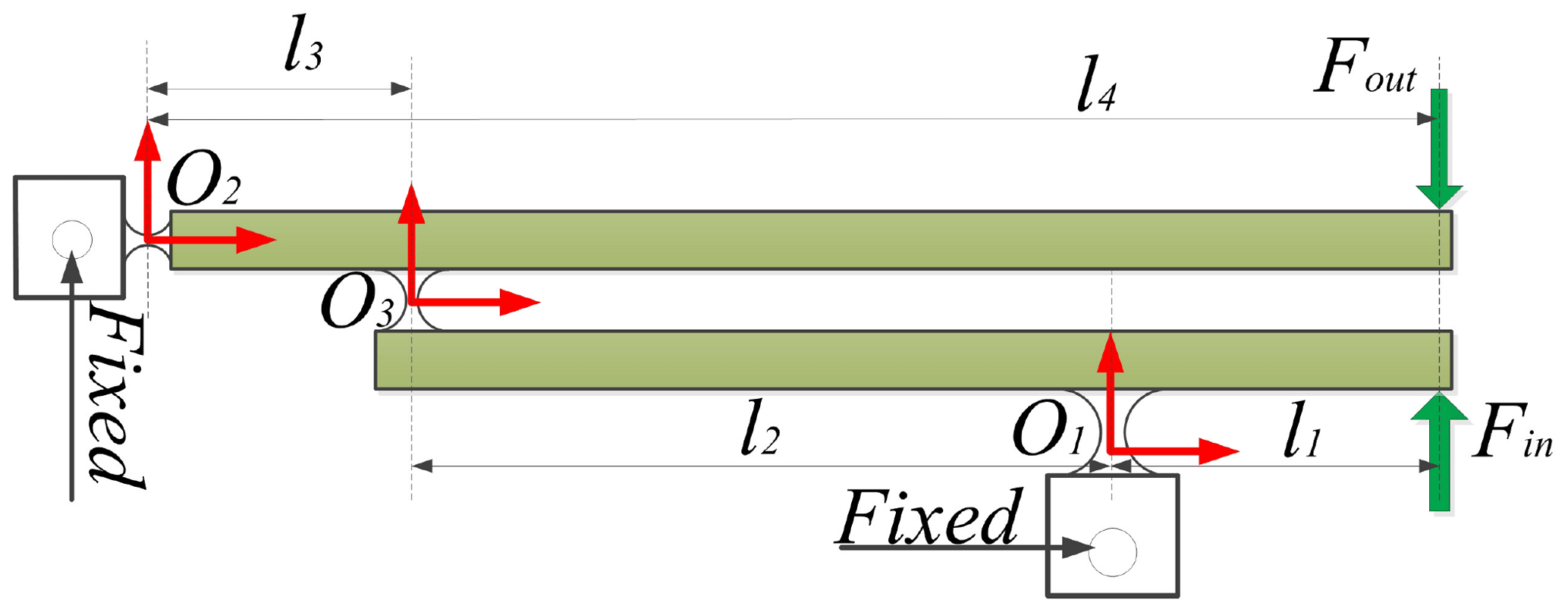
According to the mechanical principle, supposing that an outside force Fin is applied at free-end, the corresponding deformation displacement is δ. Therefore, output displacements dout and δout are obtained. Considering Fig. 1, it can be observed that the two-stage amplifier is composed of two one-stage amplifiers. Assuming that the input displacement of two-stage magnifier is also δ, the total theoretical magnification ratio can be written by
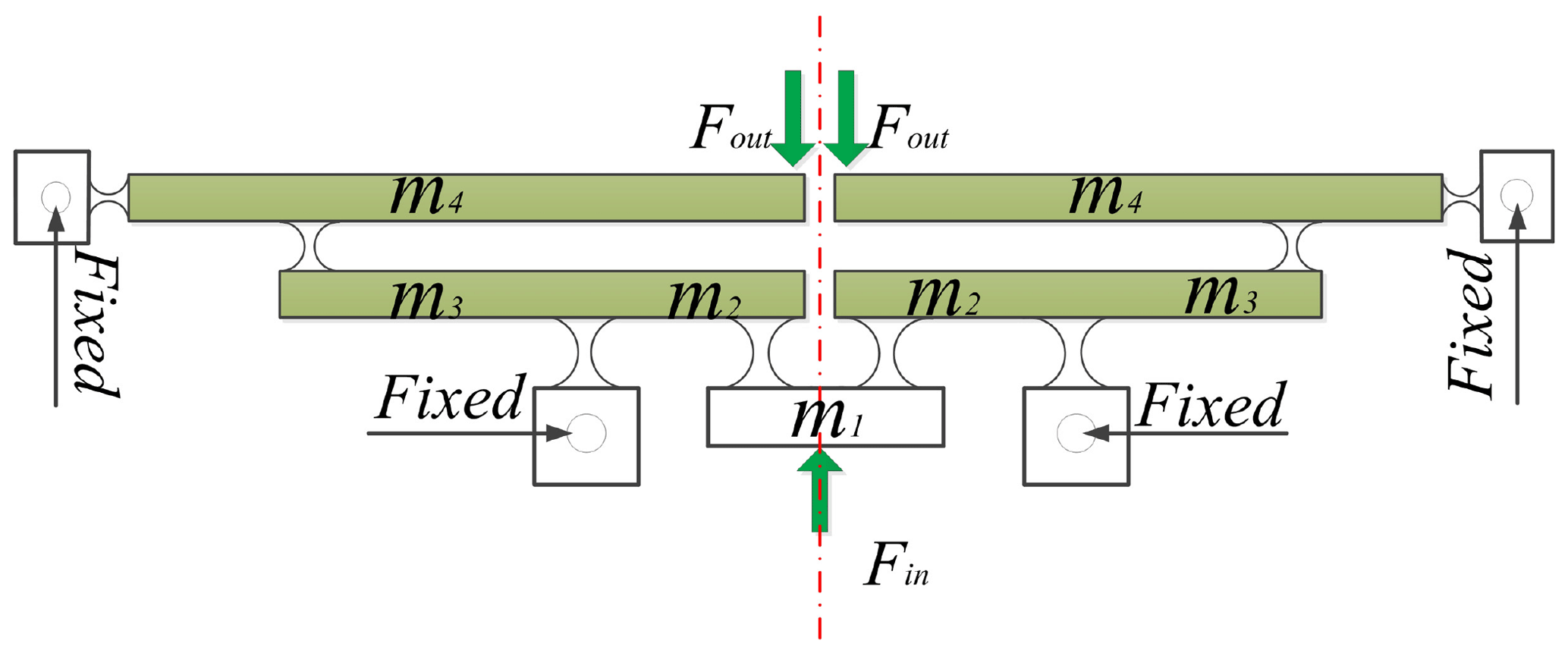
For enhancing the input stiffness, the parallel structure is used as an amplification mechanism for amplifying the input displacement as shown in Fig. 2. The mechanism is fully symmetric along with the central line and is connected by two amplifiers in parallel. The symmetrical structure of input-end of the mechanism can protect the PZT from damage.
2.2 2-DOF positioning stage
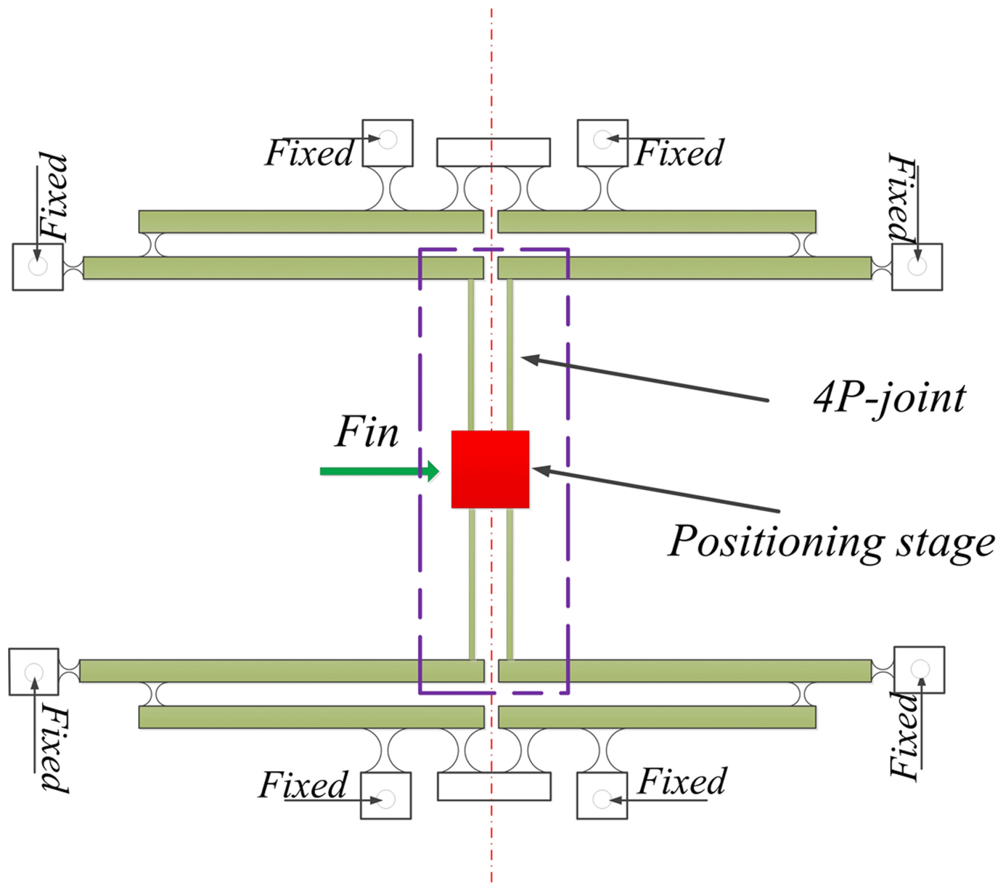
To eliminate cross coupling of the end-effector, symmetrical 1-DOF structure is shown in Fig. 3, where the double four-bar parallelogram mechanism is designed to connect the motion stage. The 4P-joint is composed of the four prismatic joints.
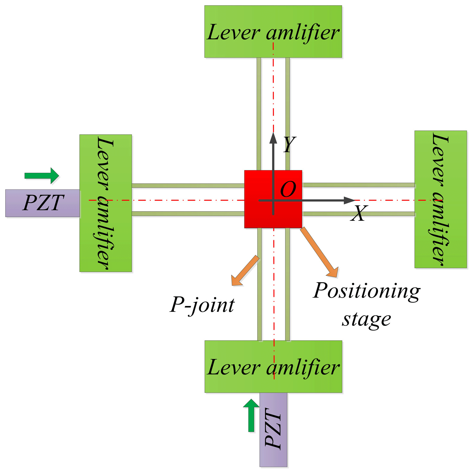
Simplified principle diagram of the 2-DOF positioning stage is presented as shown in Fig. 4, where the four mechanical displacement amplifiers and two double four-bar parallelogram mechanisms are utilized to design a fully symmetrical mechanism along with x- and y-directions. Particularly, the vertical distribution structure of two double four-bar mechanisms can effectively decrease cross coupling.
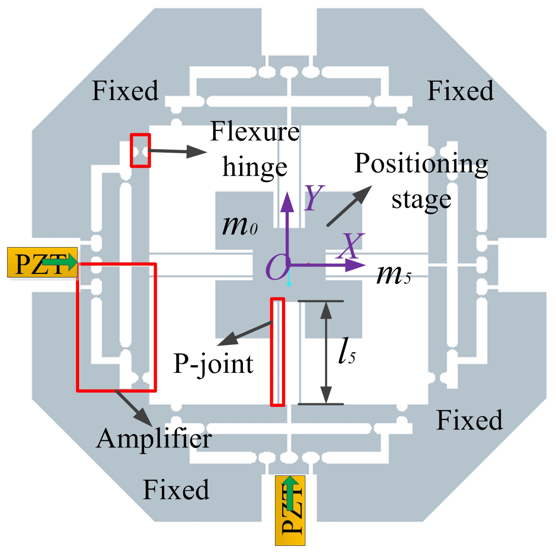
After a series of elaborated designs, three-dimension (3-D) model of the mechanism driven by PZT is proposed as shown in Fig. 5, input displacements of the motion platform, which are conducted by the PZTs installed in the x- and y-directions, can be magnified by the displacement amplifiers. Due to the symmetry of the structure and the four-bar parallelogram, parasitic motions of the positioning stage can be reduced or even eliminated. Circular hinges are adopted in the mechanical amplifier to avoid the parasitic motions.
There are many modeling methods to analyze the kinematic performance of compliant mechanism, such as the numerical model method, the pseudo-rigid-body (PRB) model method, and the compliance matrix model method (Tang and Li, 2013). In this section, kinetostatics and dynamics modeling of the compliant mechanism, including the amplification ratio (AR), input stiffness, reachable workspace and natural frequency, are analyzed by the numerical modeling method and Lagrange's method.
3.1 Amplification ratio and input stiffness analysis
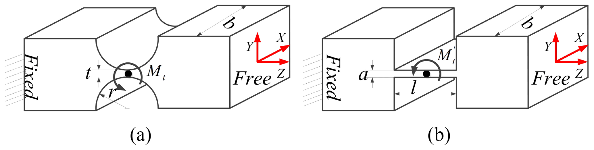
Firstly, the amplification ratio and input stiffness of the mechanism are analyzed. The flexure circular notched hinge can be regarded as the general spring with bending stiffness (kb) created by lateral force, torsion stiffness (kt) caused by the torque and linear stiffness (kl) produced by the axial force. Additionally, and are the torsion stiffness and linear stiffness of the prismatic beam (Koseki et al., 2002). Therefore, the rotational and linear deformations may simultaneously occur when a force is applied at the free-end of the beam. As shown in Fig. 6, the simplified diagrams of the circular notched hinge and prismatic beam are presented. Additionally, the torque Mt is produced after a small deformation angle Δθ occurs along with the center of the hinge from inside of the flexure hinge. Therefore, stiffness of different directions for flexure hinge can be represented in the following equations:
where E is the elastic modulus, b is the thickness of the flexure hinge, r and t are radius and smallest thickness of the circular notched hinge, a and l are the width and length of the prismatic beam, respectively.
Supposing that an input displacement δin is applied at the input-end of the mechanism, the corresponding input force and output displacement can be expressed by
where λAR and Kin are the amplification ratio and input stiffness of the micromanipulator, respectively.
Due to the symmetry, only half of the amplifier mechanism is analyzed. According to the assumptions of literatures (Su and Yang, 2001a), force analysis simplified diagrams of the mechanical amplifiers are drawn up as shown in Fig. 7, where the Fig. 7b and c are two kinds of different one-stage amplifiers (Su and Yang, 2001b). Therefore, in consideration of the force and moment balance at the equilibrium state of the beam 2, the following equations can be derived as
where Mt and are bending moments of the points O2 and B. Additionally, the forces and can be calculated through multiplying stiffness by displacement. They are expressed by the following formulas
where and are the lateral bending stiffness caused by force and output stiffness of the point B, respectively. and are the rotational stiffness of the points O2 and B.
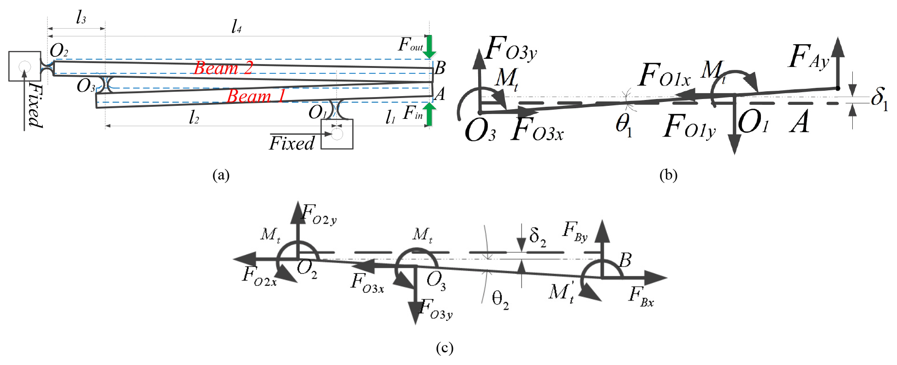
Figure 7Force diagram: (a) the deformation of the half of the amplifier; (b) forced diagram of beam 1; (c) Forced diagram of beam 2.
Substituting Eqs. (7) and (8) into Eqs. (5) and (6), the θ2 and δ2 can be derived as
Therefore, the amplification ratio and input stiffness of the beam 2 can be calculated by the following equations
Then, substituting Eqs. (9) and (10) into Eqs. (11) and (12), following formulas can be obtained as
Similarly, considering the relationship of force and moment balance at the equilibrium state for the beam 1 as shown in Fig. 7b, the following formulas can be obtained by
where and are axial stiffness and rotational stiffness of the point O1; is rotational stiffness; k2 is proposed as the stiffness of the series connection between the flexure hinge O3 and the beam 2, which can be expressed by
where is axial stiffness of the flexure hinge O3. Combining the Eq. (15) into Eq. (18), the θ1 and δ1 can be calculated by
Therefore, according to the Fig. 7b, amplification ratio and input stiffness of the beam 1 can be represented by
Substituting Eqs. (19) and (20) into Eqs. (21) and (22), they can be rewritten by
Consequently, the total amplification ratio of the two-stage lever displacement mechanism is calculated by
Additionally, total input force can be obtained by , since the amplifier is symmetric and is connected in parallel. Therefore, input stiffness can also be calculated by
For calculating the values of kin and λAR, the stiffness () of the output point B must be firstly computed. According to the Fig. 4, it can be observed that the output stiffness of the micromanipulator is the stiffness of components except from the driven amplifier. Simplified diagrams of output components are shown in Fig. 8 when the platform is driven in y-directions. The marked signs, and , are axial stiffness and rotational stiffness of the prismatic beam, respectively. And k1 is the input stiffness of the two-stage amplifier when the input-end is at the point B and output-end is at the point A as shown in Fig. 7a.
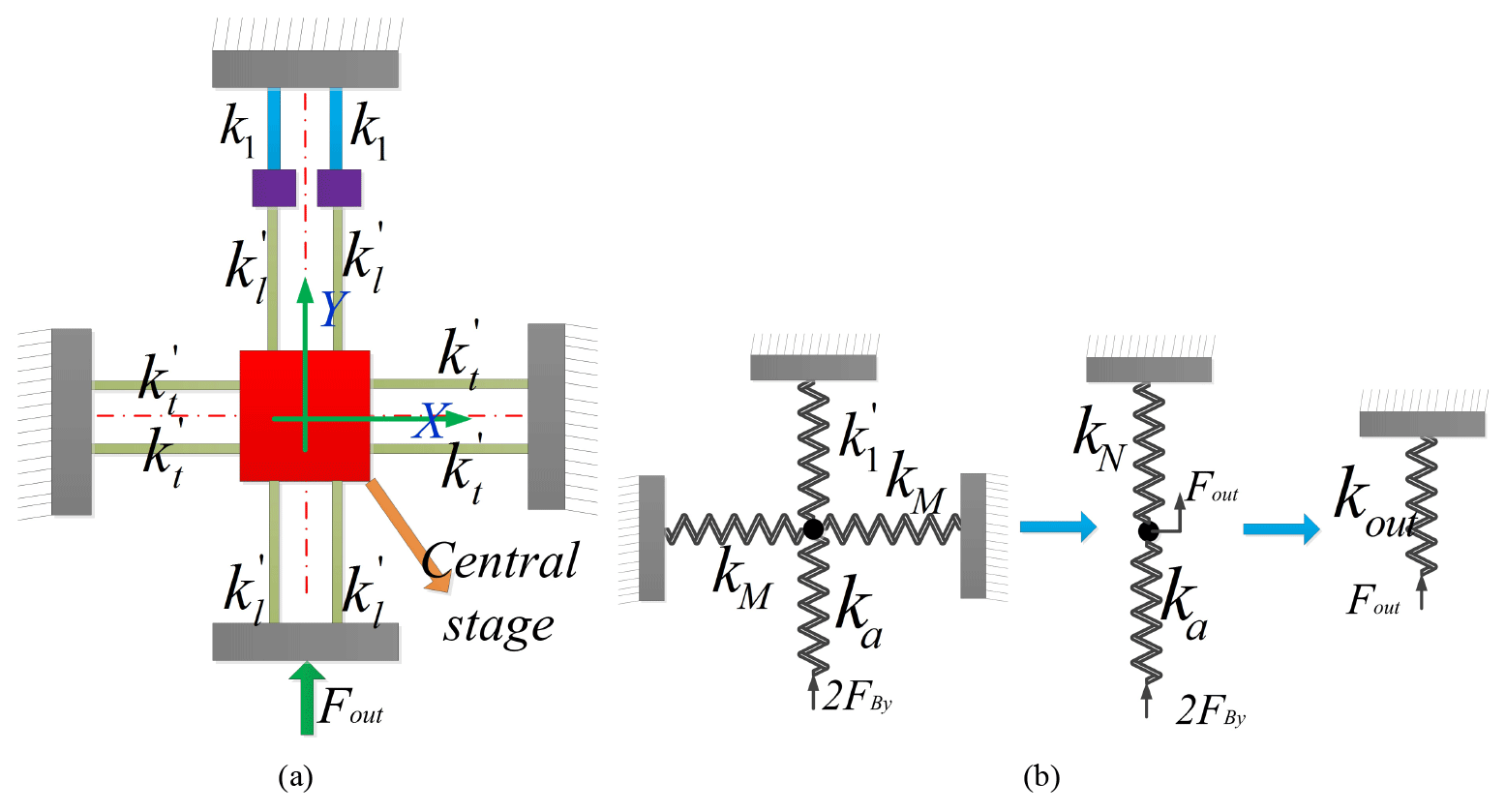
Figure 8The stiffness of output mechanism: (a) the diagram of the output mechanism; (b) the output stiffness transformation diagram.
Output displacement of the mechanism, dout, can be obtained when an input displacement din is applied at y-direction, whereas the amplifier of the x-direction will still hold since they have large transverse stiffness (Tang and Li, 2014). In addition, all rotational angles of the prismatic beams, (θ), are the same due to the identical structure. The potential energy stored in the flexible hinges can be derived as follows:
where α1, β1 and γ1 are rotational angles of flexible hinges of the amplifier and can be written by
As shown in Fig. 8b, the stiffness kN can be achieved by
According to the series-parallel relationship of the mechanism, the output stiffness kout can be expressed by the following formula
where , and are rotational stiffness and axial stiffness of the prismatic beam.
Because circular notched hinges and prismatic beams used in this study are identical, thus their stiffness can be expressed by
Due to the symmetry of the mechanism, the stiffness can be obtained by
Combining the Eqs. (25) and (32), at the same time considering Eq. (2), total amplification ratio and input stiffness of the mechanism, which can be represented by the designed parameters including r, t, a, b and , are not provided here due to page limitations. To conveniently calculate the corresponding calculations, geometric parameters and properties of the material (AL7075-T6) of mechanism are listed in Table 1.
Table 1Geometric parameters (mm) and properties of material of the mechanism.
3.2 Reachable workspace analysis
For a 2-DOF motion platform, supposing that the ARm is denoted as the amplification ratio of the mechanism and S is looked as the stroke of the PZT actuator, the workspace of the micromanipulation stage is represented by ARmS×ARmS. In this study, the bending stress only occurs on the cross section of flexible hinge when axial tension and shearing effects are not taken into consideration. Thus stress (σr) can be calculated as the following equation:
where σy and s>1 are the yield strength and the safety factor of the material. In addition, maximal stress occurs when the angular displacement θmax is maximum. It can be expressed using the following formula
where kc and f(β) are the dimensionless concentration factor and compliance factor, respectively. They are expressed by (Smith, 2000).
where is the dimensionless geometry factor.
Assuming that the maximal input displacement is , corresponding to the output displacement of the motion stage is . According to the mechanical principle, the maximal stress may occur on the hinge O3 connecting the two lever beams, since it not only suffers from the angular deformation created by output displacement, but may be also subjected to the angular deformation produced by the input displacement. Therefore, the maximal deformation angle can be derived by
Substituting Eqs. (37) into (34) and considering the Eqs. (36) and (33) at the same time, the maximal input displacement can be calculated as follows
Substituting values of the Table 1 into the Eq. (38) and letting the safety factor be 1.78. Maximal input displacement can be calculated as follows
Considering the amplification ratio of the mechanism, the output displacement of the stage can be 236.2 µm. Due to the symmetry of the mechanism, so the reachable workspace of the platform can be expressed as 236.2 µm × 236.2 µm.
3.3 Natural frequency analysis
To analyze free vibration of the 2-DOF micro positioning stage, the natural frequencies are achieved by utilizing Lagrange's method. The coordinate vector is used to describe the motions of x- and y-axes. The kinetic energy (T) and potential energy (V) stored in the mechanism can be expressed by the selected generalized coordinate and their derivations (Li et al., 2013). And then, substituting the kinetic and potential energies into the following Lagrange's equation
where , corresponds to the free vibration of x- and y-directions of the stage.
where the equivalent mass M=diag{M} and stiffness K=diag{k} are the 2×2 diagonal matrices, along with
where are shown in the Figs. 2 and 5.
Solving the Eq. (41), the natural frequency of the stage can be obtained as
which has the unit of Hertz.
In this section, the established models to evaluate the properties of the 2-DOF micromanipulation stage on aspects of amplification ratio, input stiffness, reachable workspace, and natural frequencies are verified by using FEA software (Li et al., 2012).
4.1 Model verification
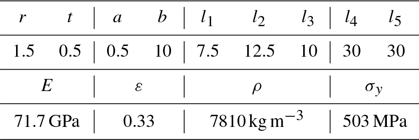
For analyzing the amplification ratio of the proposed mechanism, an input displacement with 20 µm is separately provided in the x- and y-directions and the deformation of the mechanism is shown in Fig. 9a and b, respectively. Therefore, the corresponding output displacements can be measured by selecting the points of the surface of the central platform and the average values of them are calculated with 87.58 and 87.57 µm. Additionally, the force can be also measured with 43.20 N. Therefore, the amplification ratio and input stiffness of the mechanism can be calculated as 4.38 and 2.16 N µm−1, respectively.
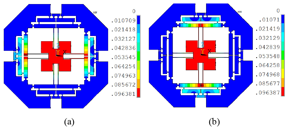
Considering the workspace within the allowable maximum stress, the maximal input displacement of the Eq. (39) is simultaneously applied at the x- and y-directions. Thus, the maximal stress distribution and the corresponding displacement deformations are shown in Fig. 10. It can be seen that the maximal stress is 278.1 MPa at the point O3, which is less than the allowable stress of the material. The Fig. 10b, c and d indicate the maximal output displacements of the whole mechanism. Based on the aforementioned analysis, the reachable workspace of the mechanism is measured with 215.50 µm × 215.50 µm.
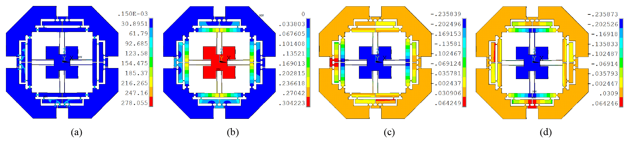
Figure 10The stress distribution and deformation diagrams: (a) maximal stress; (b) total output displacement; (c) output displacement at x-direction; (d) output displacement at y-direction.
In order to analyze parasitic motion of the mechanism, the maximal input displacement is separately applied to the x- and y-axes. As shown in Fig. 11a and b, which is the output displacement of x-direction with 215.50 µm and parasitic motion at y-direction with 0.034 µm, respectively. Similarly, the Fig. 11c and d are the output displacement at y-direction with 215.50 µm and parasitic motion of x-direction with 0.036 µm. The parasitic motions of the x- and y-directions may be caused by the model errors and the deformations of the prismatic joint.
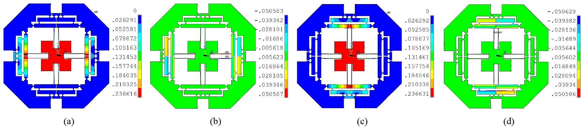
Figure 11Output displacements and parasitic motions: (a) output displacement at x-axis; (b) parasitic motion at y-direction; (c) output displacement at y-axis; (d) parasitic motion at x-direction.
For verifying the dynamic model with the natural frequencies, the first four modal shapes of the structure are expressed in Fig. 12. The first modal shape is the rotational motion, which has the frequency with 179.99 Hz. The second and third modal shapes in the x- and y-directions are almost the same with values of 354.21 and 355.32 Hz, respectively. The fourth modal shape of the Z-direction is about 867.23 Hz.
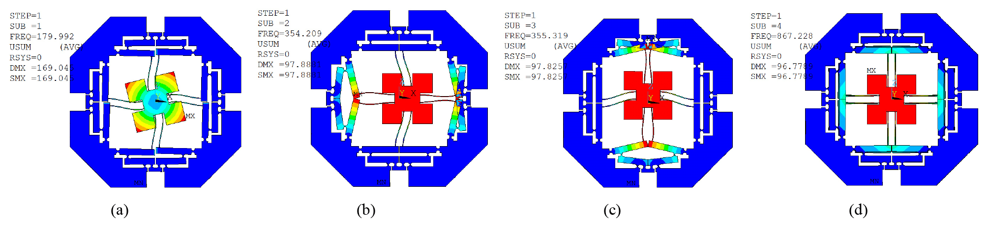
Figure 12The first four modal shapes of the mechanism: (a) the first modal shape; (b) the second modal shapes; (c) the third modal shape; (d) the fourth modal shape.
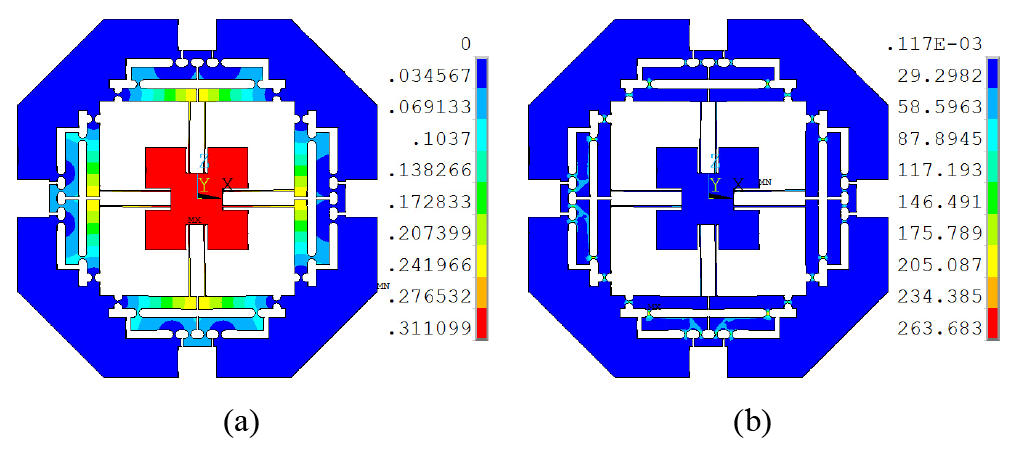
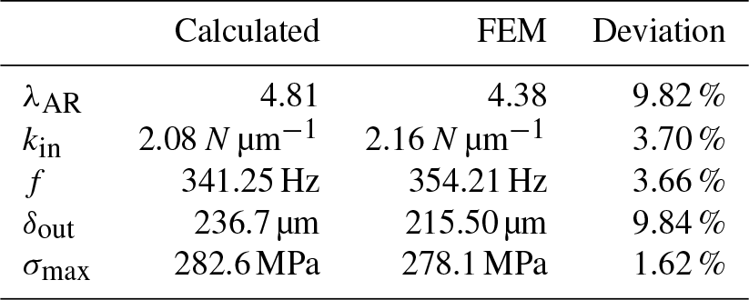
Table 2Comparison results between calculated values and simulated values.
4.2 Discussions
For further indicating the rationality of the design (Li and Wu, 2016), a comparison between the calculated values and the simulated values of FEA, in terms of amplification ratio, input stiffness, natural frequency, and maximum output displacement, is listed in Table 2. It can be observed that the maximal error is the output displacement and amplification ratio by using the benchmark of FEA. The reasons may be that the transverse deformation caused by the transverse force as shown in Fig. 7 is not taken into account in the calculated models and flexure hinge itself. In addition, the maximal stress is under the truly calculated value. The natural frequencies of the x- and y-directions are almost equivalent, which demonstrate that their performances are identical.
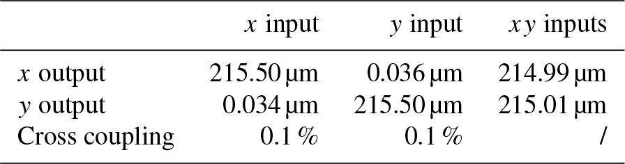
Cross coupling is the key performance of the 2-DOF micro-positioning stage. As shown in Fig. 11, the results of the maximum output displacements in two axes are listed in the Table 3. The output displacement of x-axis is 215.50 µm when input displacement is separately applied at x-direction, while the parasitic displacement of y-direction caused by x-direction is only 0.034 µm. Taking input displacement as the benchmark, coupling error of the y-axis is only for 0.1 %. Similarly, the parasitic motion of x-direction caused by y-direction is 0.036 µm with the output displacement is 215.50 µm at y-direction. Thus, coupling error on the x-axis is only for 0.1 % more than that of y-axis. Additionally, output displacements of x- and y-axes are up to 214.99 and 215.01 µm when the input displacements are simultaneously applied in the x- and y-directions. Based on the aforementioned analysis, the 2-DOF micromanipulation stage has low cross coupling and owns the best decoupling property.
The parameters of the architecture by using the Genetic Algorithm (GA) method are optimized to obtain the best kinematic characteristic of the xy stage (Wang et al., 2014). In practical applications, the actual amplification ratio of mechanical amplifier is less than the theoretical value, which is arisen from the combination of the deformation of hinge and lever arm bending. Additionally, considering analytical models overestimate the performance of the stage with deviations around 5 %–30 %, a compensation factor, ε=0.75, is used in the optimization process to rebuild the models.
5.1 Optimization problem description
Based on aforementioned equations, which reveal that the performances of the 2-DOF micro-positioning stage rely on the relative parameters. All established models mainly include these parametric variables: r, t, a, b, l1, l2, l3, l4, l5, which influence the synthetical property of the stage.
For the mechanism with a special thickness (b=10 mm in this study), only eight parameters (r, t, a, l1, l2, l3, l4, l5) need to be optimized. While other parameters can be determined by taking into account the length and width restrictions of the PZT with the addition of an appropriate assembling space. Otherwise, input stiffness of the mechanism should not surpass the minimum stiffness of the PZT. According to the geometrical relation of the structure, these variables should satisfy the following equation
With the selection of the amplification ratio of the stage as an objective function, the optimization process can be stated as follows:
- a.
Maximum: Amplification ratio (λAR≥7).
- b.
Variables to be optimized: r, t, a, l1, l2, l3, l4, and l5.
- c.
Subjecting to:
- 1.
Input stiffness value εkin≤KPZT;
- 2.
Natural frequency εf≥150 Hz;
- 3.
Theoretical amplification ratio AR≥7;
- 4.
Suffering from the restrictions of Eq. (45);
- 5.
The ranges of parameters:
1.5 mm ≤ r≤2.0 mm, 0.3 mm ≤ t≤0.8 mm,
0.3 mm ≤ a≤1 mm, 5 mm ≤ l1≤15 mm,
7 mm ≤ l2≤20 mm, 5 mm ≤ l3≤15 mm,
20 mm ≤ l4≤40 mm, 28 mm ≤ l5≤40 mm.
- 1.
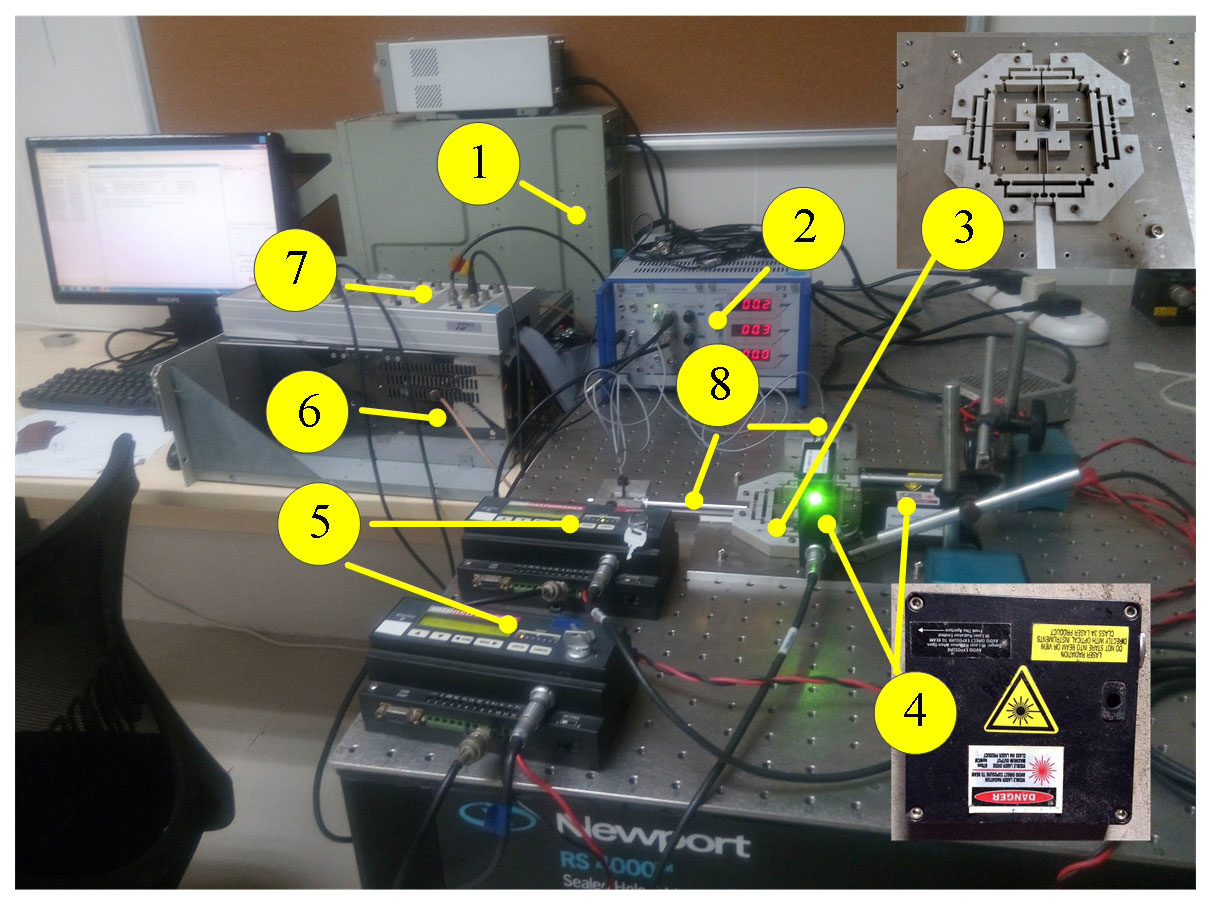
Figure 14The experimental setup. (1) Host computer, (2) signal amplifier and controller, (3) compliant mechanism, (4) laser sensors, (5) laser collectors, (6) dSPACE controlling system, (7) DAQ board, (8) PZT actuators.
5.2 Optimal results
The Genetic Algorithm (GA) is adopted in the current issue due to its superiority of fast convergence, fewer calculating time and higher robustness over other method such as simulated annealing algorithm (Mccall, 2005). The optimization process is implemented by the GA toolbox of the MATLAB software and the results of optimized parameters are: r=1.5 mm, t=0.78 mm, a=0.5 mm, l1=5.47 mm, l2=14.57 mm, l3=7.90 mm, l4=27.94 mm, l5=28 mm, which will lead to an xy stage with λAR=7.87, kin=13.39 N µm−1 and the natural frequency f=367.07 Hz.
After optimization, simulation is carried out for demonstrating performances of the optimized micromanipulation stage. Maximum input displacements are applied at x- and y-axes and the total deflection and stress distribution of the mechanism are expressed in Fig. 13. It is observed that the output displacement of x-axis is 94.90 µm, and the corresponding input force is 214.63 N. Therefore, the optimized mechanism has an amplification ratio of 4.75 with an input stiffness of 10.63 N µm−1. In addition, maximal stress is 263.68 MPa, which is far less than the yield strength of the material.
Furthermore, the first four natural frequencies are also analyzed and their values are 174.26, 348.31, 350.14 and 850.65 Hz, respectively. They are all less than the frequencies before optimizing and the frequencies of x- and y-directions are very close to the calculated values, which demonstrate that the structure optimization is effective.
6.1 Experimental setup
After fabricating, experimental setup of the micro-positioning stage is shown in Fig. 14. Two PZTs with stroke of 90 µm (model P-840.60 produced by Physik Instrumente, Inc.) are adopted to drive the micromanipulation stage, and the PZTs are actuated with a voltage of 0–100 V through a three-axis piezo-amplifier and driver (E-509 from the PI). Two laser displacement sensors and collectors (Microtrak II, head model: LTC-025-02, from MTI Instrument, Inc.) are used to measure the end-effector displacements of the two axes. The analog outputs of two sensors are connected to a PCI-based data acquisition (DAQ) board (PCI-6143 with 16-bit A/D convertors, from NI Corp.) through a shielded I/O connector block (SCB-68 from NI) with noise rejections. The digital outputs of the DAQ board are read by a host computer simultaneously.
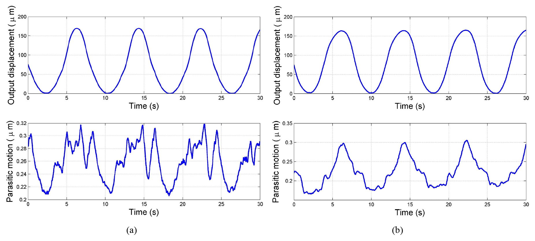
Figure 15The output displacements and parasitic motions: (a) the output displacement of x-axis and parasitic motion of y-axis; (b) the output displacement of y-axis and parasitic motion of x-axis.
Since the sensitivity of the laser sensor is 2.0 mm/10 V and the maximum value of 16-bit digital signal corresponds to 10 V, the resolution of the displacement detecting system can be calculated as
However, due to a considerable level of the noise, the resolution of the sensor is claimed ±0.2 µm by the manufacturer. In the process of practical precision motion control experiments, it is found that the limitation of the fabricated prototype mainly arises from the laser displacement sensors which have a not-high resolution of ±0.2 µm.
6.2 Open test
To describe the dynamic properties of the proposed mechanism, the corresponding open-loop tests are carried out by using the dSPACE real-time simulation control system. As shown in Fig. 15a and b, which demonstrate respectively the output displacements and parasitic motions of x- and y-directions when the input voltage is . The results indicate that the actual amplification ratio of the mechanical amplifier in x-direction by comparing the input and output displacements is about 3.51 and the parasitic motion for the y-direction is about 0.32 µm. While one of y-direction is calculated as 3.43 and the parasitic motion for the x-direction is only 0.31 µm. Based on the aforementioned tests, the experimental results are less than the analytical results. The main reasons may come from the assembly errors of the system and the preloaded force of the PZT. Additionally, parasitic motions of the x- and y-axes are very small, which can be ignored. Therefore, testing results demonstrate that the designed mechanism has excellent decoupled performance.
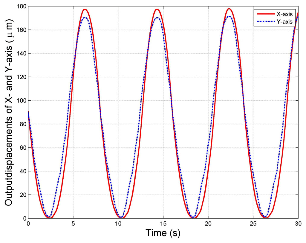
To further illustrate the kinematic performance of the micro-positioning stage, the testing results of the x- and y-axes are shown in Fig. 16 when the two PZTs at x- and y-directions are driven simultaneously. The results indicate that the output displacements of x- and y-directions are not identical. The errors may be created by the preloaded force of PZTs and manufacturing defects between two axes.
6.3 Tracking experiments
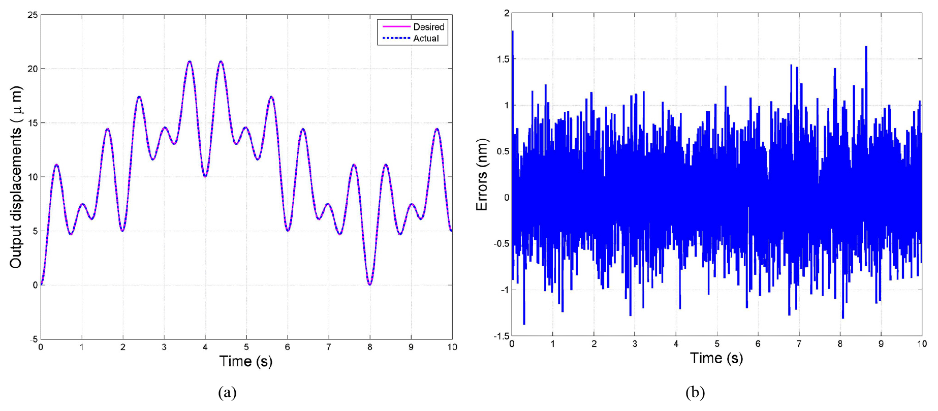
For further validating the performances of micro/nano-positioning platform, a robust tracking controller is used to obtain the well tracking effect. The reference input displacement is the signal with different frequencies since the hysteresis phenomenon of piezoelectric actuator is a rate-dependent hysteresis. Therefore, the robust controller can effectively eliminate the drawback caused by rate-dependent of the PZT-actuated micromanipulator. The tracking results and corresponding errors is shown in Fig. 17, where output displacement is well tracking with the input displacement and the error is low than 0.01 %. Thus the optimal design is suitable for this compliant mechanism.
6.4 Discussions
From the Figs. 15 and 16, we can see that the output displacements of the x- and y-axes are not exactly same, the main reasons maybe come from the errors coming from installation and manufacturing. Thus, the rotation of end-effector can exist, but it may be minor affections for the other orientation.
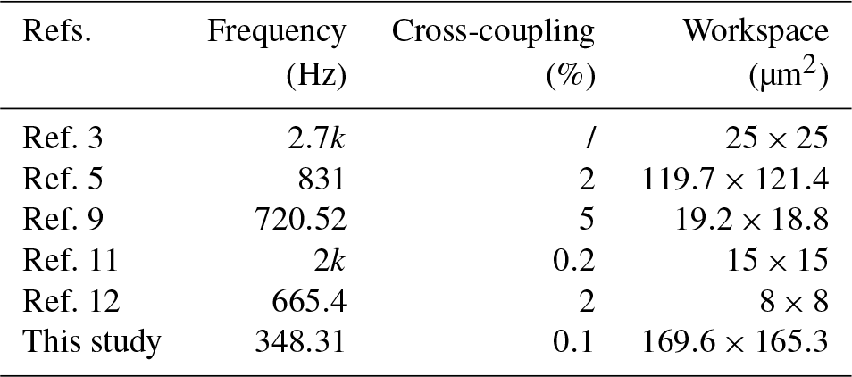
Based on aforementioned modeling, analyzing, and testing, the results demonstrate that the proposed 2-DOF micro-positioning stage with mechanical amplifier owns some advantages, in terms of large motion, and low cross coupling. A comparison with other proposed 2-DOF stages are completed in Table 4. The natural frequencies of the presented stages in Ref. 3 and Ref. 11 are higher than other mechanisms, but their working ranges are very small, which seriously limit their further applications. Additionally, the performances in terms of cross coupling and workspace of the other two stages presented in Ref. 5, Ref. 9 and Ref. 12 are obviously lower than the proposed in this study.
In this paper, a novel fully decoupled xy micro-positioning stage with lever amplifier has been proposed. The designing process of the stage is provided in consideration of the decoupled property of the output motions. In addition, the analytical method and Lagrange's method are adopted for the kinematics and dynamics modeling of the mechanism with amplification ratio, stiffness, reachable workspace and natural frequency. The modeling verification and performance evaluation are carried out by FEA. Considering the performance requirement, a series of structural optimizations by using GA method have been implemented to improve the amplification ratio. Finally, prototype fabrication and experimental tests are implemented in detail. All results indicate that the maximal cross coupling of the 2-DOF micro-positioning stage is less than 0.1 % under the workspace for 169.6 µm × 165.3 µm with the natural frequency of 348.31.
For further study, intelligent controller is going to be considered to control the micro-positioning stage and precise position tracking will be carried out in our future work.
This experimental data can be downloaded at https://pan.baidu.com/disk/home?errno=0&errmsg=Auth Login Sucess&&bduss=&ssnerror=0&traceid=#/all?path=/&vmode=list (last access: 20 November 2018).
The main contribution for ZW includes the structural design, modeling analysis and the control. The contribution for co-author MH includes the structural optimization. And the contribution for co-author YL includes the structural design and the English writing error and grammar modification.
The authors declare that they have no conflict of interest.
This work was supported in part by Science and technology research project of
department of education, Jiangxi, China (GJJ170568), National Natural Science
Foundation of China (51575544, 51275353), Research Committee of The Hong Kong
Polytechnic University (1-ZE97, G-YZ1G).
Edited by: Xichun Luo
Reviewed by: Calin-Octavian Miclosina
and one anonymous referee
Choi, S. B., Han, S. S., Han, Y. M., and Thompson, B. S.: A magnification device for precision mechanisms featuring piezoactuators and flexure hinges: design and experimental validation, Mech. Mach. Theory, 42, 1184–1198, 2007. a
Dong, J. D., Mukhopadhyay, D., and Ferreira, P. M.: Design, fabrication and testing of a silicon-on-insulator (SOI) MEMS parallel kinematics XY stage, J. Micromech. Microeng., 17, 1154–1161, 2007. a
Dong, Y., Gao, F., and Yue, Y.: Modeling and experimental study of a novel 3-RPR parallel micro-manipulator, Robot. Cim.-Int. Manuf., 37, 115–126, 2016. a
Fan, S., Liu, H., and Fan, D.: Design and development of a novel monolithic compliant XY stage with centimeter travel range and high payload capacity, Mech. Sci., 9, 161–176, 2018. a
Hao, G., Li, H., and Kavanagh, R.: Design of Decoupled, Compact, and Monolithic Spatial Translational Compliant Parallel Manipulators Based on the Position Space Concept, P. I. Mech. Eng. C–J. Mec., 230, 367–378, 2016. a
Koseki, Y., Tanikawa, T., Koyachi, N., and Arai, T.: Kinematic analysis of a translational 3-d.o.f. micro-parallel mechanism using the matrix method, Adv. Robotics, 16, 95–105, 2002. a
Li, Y. M. and Wu, Z. G.: Design, analysis and simulation of a novel 3-DOF translational micromanipulator based on the PRB model, Mech. Mach. Theory, 100, 235–258, 2016. a
Li, Y. M., Huang, J. M., and Tang, H.: A compliant parallel XY micromotion stage with complete kinematic decoupling, IEEE T. Automat. Sci. Eng., 9, 538–553, 2012. a
Li, Y. M., Wu, Z. G., and Zhao, X. H.: Optimal design and control strategy of a novel 2-DOF micromanipulator, Int. J. Adv. Robot. Syst., 10, 1–13, 2013. a
Lin, C. J. and Lin, P. T.: Particle swarm optimization based feedforward controller for a XY PZT positioning stage, Mechatronics, 22, 614–628, 2012. a
Liu, P., Yan, P., Zhang, Z., and Leng, T.: Modeling and control of a novel X−Y parallelpiezoelectric-actuator driven nanopositioner, ISA T., 56, 145–154, 2015. a
Mccall, J.: Genetic algorithms for modelling and optimisation, J. Comput. Appl. Math., 184, 205–222, 2005. a
Polit, S. and Dong, J.: Development of a high-bandwidth XY nanopositioning stage for high-rate micro-/nanomanufacturing, IEEE/ASME Transactions on Mechatronics, 16, 724–733, 2011. a
Qin, Y., Shirinzadeh, B., Tian, Y., and Zhang, D.: Design issues in a decoupled XY stage: Static and dynamics modeling, hysteresis compensation, and tracking control, Sensor. Actuat. A-Phys., 194, 95–105, 2013. a
Smith, S. T.: Flexures: elements of elastic mechanisms, Gordon and Breach, New York, 2000. a
Su, X. P. and Yang, H. S.: Design of compliant microleverage mechanisms, Sensor. Actuat. A-Phys., 87, 146–156, 2001a. a
Su, X. P. and Yang, H. S.: Single-stage microleverage mechanism optimization in a resonant accelerometer, Struct. Multidiscip. O., 21, 246–252, 2001b. a
Tang, H. and Li, Y. M.: Design, Analysis, Test of a novel 2-DOF nanopositioning system driven by dual mode, IEEE Transation on Robotics, 29, 650–662, 2013. a
Tang, H. and Li, Y. M.: Development and active disturbance rejection control of a compliant micro/nano-positioning piezo-Stage with dua-mode, IEEE T. Ind. Electron., 61, 1475–1492, 2014. a
Tang, H. and Li, Y. M.: A new flexure-based Yθ nanomanipulator with nanometer-scale resolution and millimeter-scale workspace, IEEE/ASME Transation on Mechatronics, 20, 1320–1330, 2015. a
Tian, Y., Shirinzadeh, B., and Zhang, D.: A flexure-based mechanism and control methodology for ultra-precision turning operation, Precis. Eng., 33, 160–166, 2009. a
Wang, F., Li, J., Liu, S., Zhao, X., Zhang, D., and Tian, Y.: An Improved Adaptive Genetic Algorithm for Image Segmentation and Vision Alignment Used in Microelectronic Bonding, IEEE/ASME Transation on Mechatronics, 19, 916–923, 2014. a
Wu, Z. G. and Li, Y. M.: Optimal design and control strategy of a novel 2-DOF micromanipulator, Int. J. Adv. Robotic Syst., 10, 1–13, 2014. a
Yong, Y. K., Aphale, S. S., and Moheimani, S. O.: Design, Identification, and Control of a Flexure-Based XY Stage for Fast Nanoscale Positioning, IEEE Transation on Nanotechnology, 8, 46–54, 2009. a
Yu, J., Xie, Y., Li, Z., and Hao, G.: Design and Experimental Testing of an Improved Large-range Decoupled XY Compliant Parallel Micromanipulator, J. Mech. Robot., 7, 044503, https://doi.org/10.1115/1.4030467, 2015. a
Yu, Y. Q., Du, Z. C., Yang, J. X., and Li, Y.: An Experimental Study on the Dynamics of a 3-RRR Flexible Parallel Robot, IEEE Transation on Robotics, 27, 992–997, 2011. a