the Creative Commons Attribution 4.0 License.
the Creative Commons Attribution 4.0 License.
 | 05 Oct 2018
Novel compliant wiper mechanism
Raşit Karakuş
Conventional wiper mechanisms that are used in automotive vehicles comprise numerous linkages and joints. In this study, in order to obtain a simpler design, a novel compliant wiper mechanism is introduced. The wiper mechanism is essentially a partially compliant four-bar mechanism. To the best of our knowledge, this is the first compliant wiper mechanism in the literature. The wipers currently labeled “compliant” in the literature possess only a flexible wiper blade frame. However, these are still driven by conventional rigid body mechanisms. After introduction of the fundamental concept, a compliant wiper mechanism is designed for an L7e car. Finite element analysis is carried out for verifying analytical results and fatigue calculations are performed. Finally, a prototype is manufactured, and it is experimentally verified that a compliant wiper mechanism may have an infinite life.


Mechanisms that gain some or all of their motion through the deflection of flexible members are classified as compliant mechanisms (Howell, 2001). There are significant advantages of compliant mechanisms, such as low cost, light weight, fewer parts, little or no maintenance requirement, less wear and noise, and high accuracy. Furthermore, a compliant mechanism can store elastic energy during the elastic deformation that can be used for different purposes, such as restoring the mechanism to its original position without a separate spring. Compliant mechanisms have a wide area of use thanks to those advantages (Fowler et al., 2011).
Compliant mechanisms can be broadly classified as fully compliant or partially compliant (Howell, 2001; Lobontiu, 2002). There are several methods in the literature used for design and analysis of compliant mechanisms (Cao et al., 2013; Lan, 2008; Venanzi et al., 2010). A compliant mechanism can be modeled with rigid links, joints, and torsional springs by using the pseudo-rigid body model (PRBM) method. In this method, flexural segments are assumed to behave like revolute with torsional springs (Howell, 2001; Lobontiu, 2002). Using this technique, compliant mechanisms can be analyzed and synthesized similarly to rigid body mechanisms. Rigid mechanism synthesis is the preliminary step in the design of a compliant mechanism.
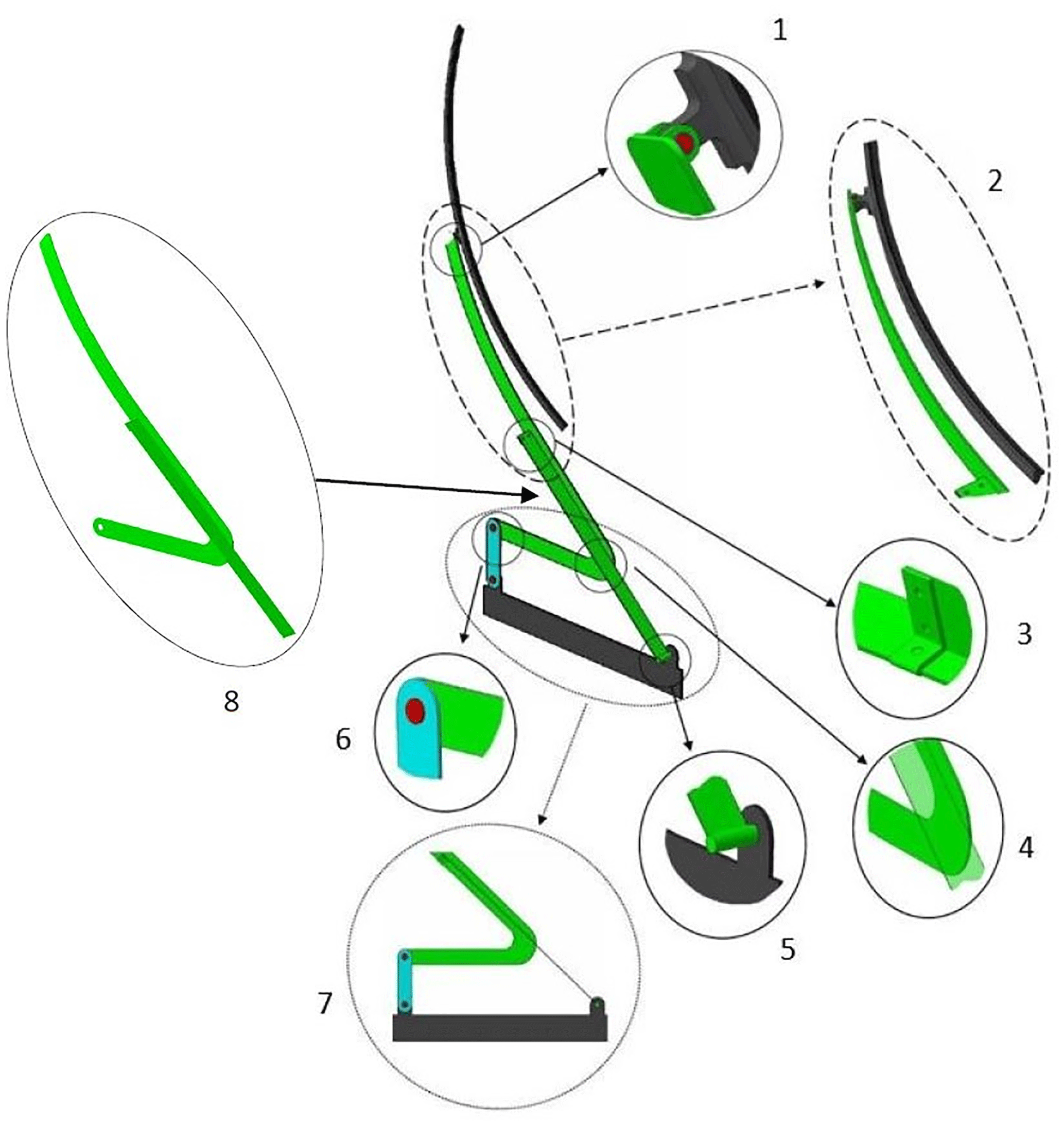
Our patented design (Tanık and Karakus, 2013) (TR 2013-10617), “an original partially compliant wiper mechanism”, is presented in Fig. 1. The flexible links (rocker link and wiper blade pressing arm) and coupler of the four-bar mechanism are designed as a single piece. This design decreases the number of manufacturing steps of the wiper mechanism by forming coupler and rocker links together, from a single piece of steel sheet. The wiper pressing arm is a curved segment which is an extension of the rigid segment of the compliant link. The curvature of this arm provides the required pressing force on the windscreen, since there is no additional torsional spring in the structure. This design provides a significant reduction in the number of parts compared to the conventional rigid wiper mechanism. A detailed isometric view of the wiper mechanism is presented in Fig. 1.
-
Connection between wiper blade and wiper pressing arm
-
Wiper blade and curved wiper blade pressing arm
-
Connection between coupler and rocker (compliant link)
-
Relative position of coupler and rocker. At the undeflected position of the compliant link, the coupler and rocker links are overlapped and stay parallel to each other.
-
Connection of rocker to fixed link by revolute joint
-
Revolute joint between crank and coupler
-
Top view of the mechanism
-
Coupler, compliant rocker, and wiper pressing arm as a single piece
In this study, initially, a single-arm rigid wiper mechanism is designed. The rigid mechanism is evaluated for its effectiveness on sweeping areas for an L7e vehicle. By using the rigid body replacement method, a compliant wiper mechanism is then dimensioned. In order to verify the strength of the compliant segment, an analytical approach is adopted and a finite element analysis (FEA) is performed. Finally, a prototype is manufactured, and the theoretical approaches are compared with the experimental data.
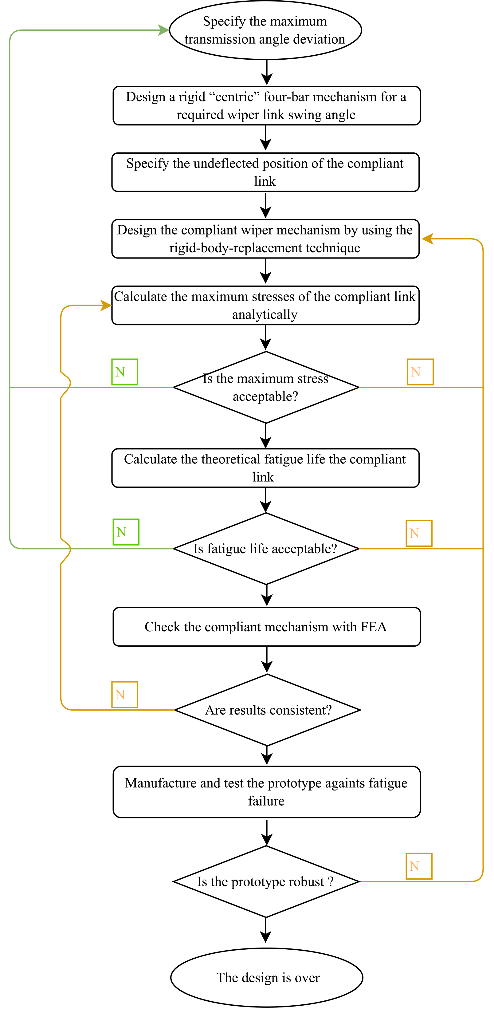
The design procedure is summarized as a flowchart which is presented in Fig. 2. The following design and analysis procedures are performed according to this flowchart. It should be noted that the loops associated with orange lines have priority. After several iterations, if the design is still unacceptable, the loop with green lines should be followed.
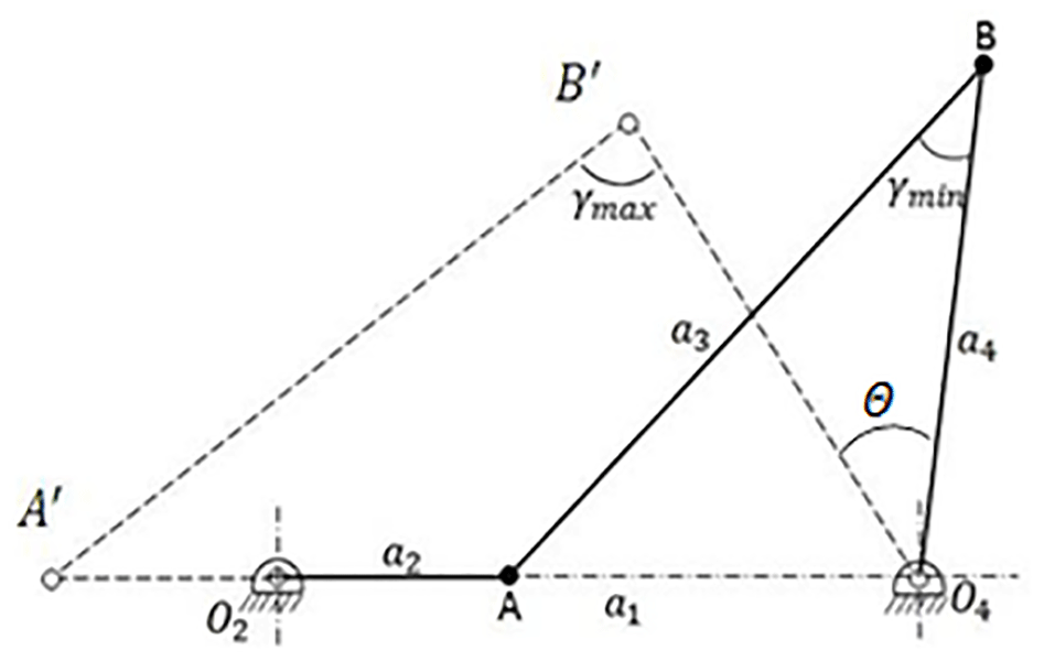
The wiping action is typically performed by mechanisms that are limited to moving between two prescribed positions. In this section, a two-position synthesis method is implemented to determine link proportions for an appropriate rigid four-bar mechanism to be used for the rigid body replacement synthesis. There are numerous two-position mechanism design methods in the literature. Brodell and Soni (1970) described the synthesis of a crank-rocker mechanism with an optimum transmission angle. In this method, the transmission angle between the coupler and output link (shown as γ in Fig. 3) deviates the same amount from 90∘ for a full rotation of the crank – Eq. (1). Therefore, if the undeflected position of the compliant segment is set to during the PRBM replacement synthesis, the deflection of the compliant segment will be the same in both directions. In addition, with this method, as the transmission angle (Alt, 1932; Balli and Chand, 2002; Tanık, 2011) is at an optimum, the motion quality of the synthesized mechanism will be satisfactory. The Brodell and Soni (Brodell and Soni, 1970) analytical method equations are
In Eqs. (2)–(4), γmin and Θ are optimization parameters, where Θ is the output swing angle. Once these two parameters are determined, the link proportions are determined accordingly. The fixed link, a1, is the scale factor of the mechanism. It should be noted that, according to the study of the transmission angle of a compliant mechanism (Tanık, 2011), compliance of a compliant mechanism may cause a difference in transmission characteristics compared to its rigid body counterpart. However, in that study, it was proved that “the transmission characteristics of a compliant mechanism will be similar to those of its rigid body counterpart if the output loading is large relative to the stiffness of a compliant link”. Similarly, in this study, after the force analysis which is presented in Sect. 5 we observed that the forces acting on the output link are also large relative to the stiffness of the compliant link. Therefore, it is acceptable to proceed with this study considering the transmission angle of a rigid body counterpart.
2.1 Dimensioning criteria: an experimental L7e car
In order to obtain a realistic test platform, we aim to design a compliant wiper mechanism for a windscreen of an L7e car (Tanık and Parlaktaş, 2015) as seen in Fig. 4a. The dimensions of the windscreen are presented in Fig. 4b.
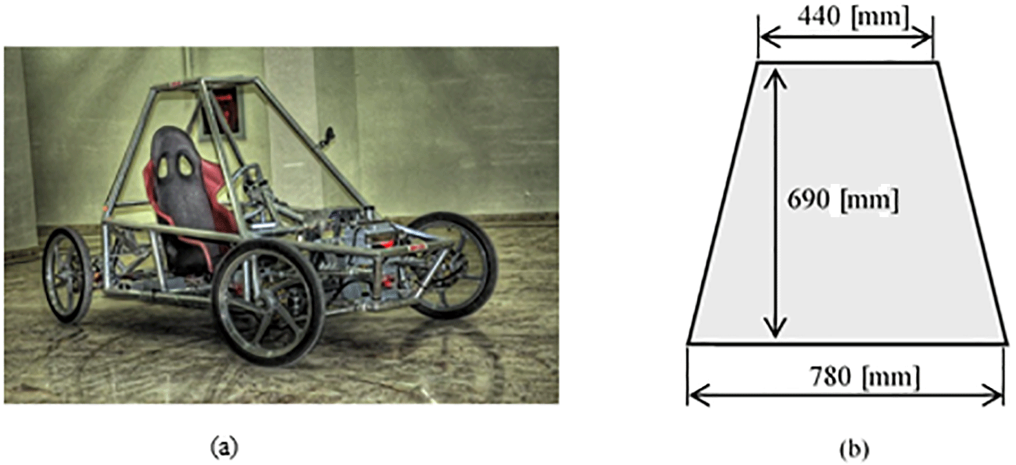
2.2 Dimensional optimization
In this section, the major optimization criterion is to maximize the swept area, while the transmission angle remains in an acceptable range. It is observed that a smaller minimum transmission angle results in an increase in the swept area. However, the motion transmission efficiency decreases significantly as the deviation of the transmission angle increases from 90∘. The design procedure and the optimization routine are performed considering the L7e electric car (Fig. 4a). According to the dimensions given in Fig. 4b, the free parameters are selected as and and link 1 is heuristically optimized for the L7e car as a1=400 mm. We then calculated the dimensions of the rigid four-bar mechanism by using the following values in Eqs. (2)–(4):
Wiper blade pressing arm length (Lv) (enlarged view 2 in Fig. 1: the length of the curved beam) is taken as
Lv should be approximately equal to half of the wiper arm length (Fig. 5a) so that the wiper blade applies a balanced force towards the windshield.
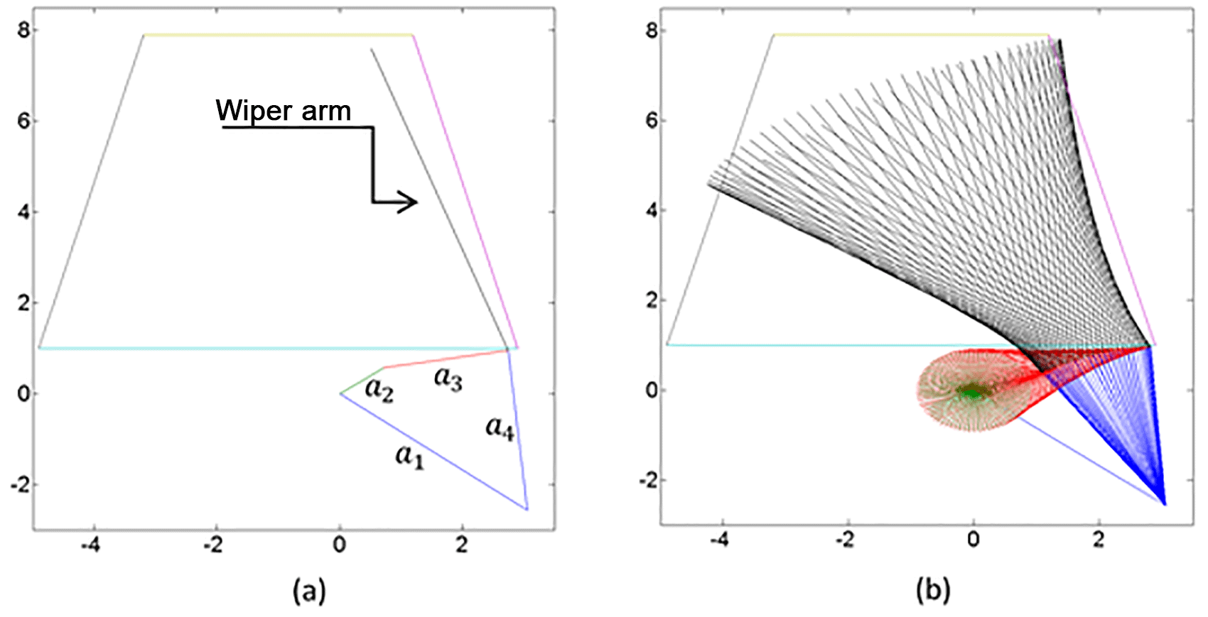
2.3 Calculation of the swept area and orientation of the mechanism
As the wiper blade is attached to the coupler link that executes general plane motion in our design, calculation of the swept area is not as simple as in a conventional wiper mechanism, where the blade is attached to the rocker link and performs a fixed-axis rotation. In order to determine the wiper performance by means of the percentage of swept area over the visible area of the windscreen, an image processing code is used. It should be noted that numerous orientations are evaluated to obtain a satisfactory sweeping area. The orientation of the mechanism and the swept area are presented in Fig. 5. This process is also used for determining the wiper blade length and is selected as 70 cm.
After the image processing, the swept area to windscreen area ratio is determined as 63 %, which is acceptable. This iteration process is also a part of the optimization step of the transmission angle of the PRBM. It should be noted that it is possible to increase the swept area by deviating the transmission angle from 90∘. However, when the deviation is increased excessively, the motion transmission efficiency decreases significantly.
In this section, we determine the dimensions of the compliant wiper mechanism by using a rigid-body-replacement synthesis technique (Howell, 2001). Numerous different compliant mechanisms can be designed from a single rigid body mechanism. However, in order to obtain a high oscillating output (wiper arm) with relatively low stresses, we preferred a “long simple compliant segment” (Figs. 1 and 6) for the compliant link, rather than a small length flexural compliant segment. The mechanism is displayed in a simplified form in Fig. 6. The mechanism is a partially compliant mechanism with two rigid links and one compliant link (link 3). There are three rigid segments and one simple compliant segment.
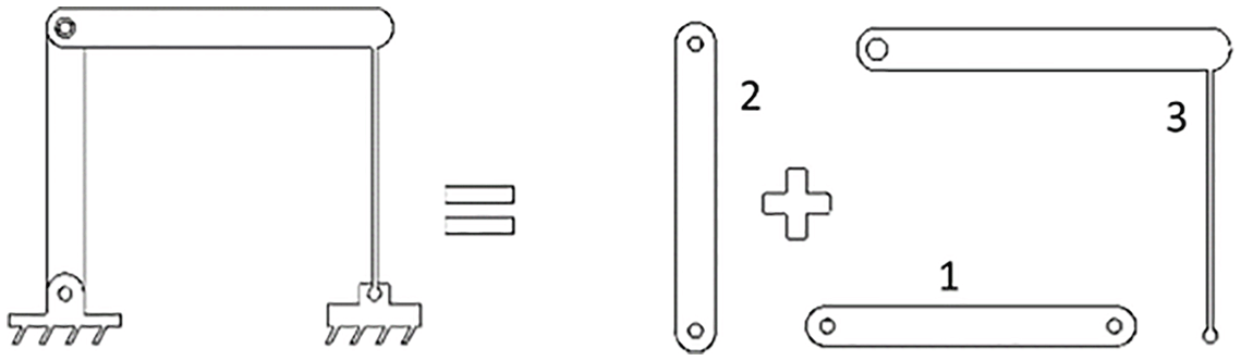
Link 1 in Fig. 6 is the fixed link and link 2 is the crank, i.e., the input link of the mechanism, and performs a full rotation. Link 3 is the compliant link, formed from one rigid segment and one compliant segment, and it is the output link of the mechanism. The wiper blade is attached to the rigid segment of this link. There are three kinematic pairs (revolute joints) available in the mechanism. The compliant segment of the output link is connected to the ground by a revolute joint, where the moment is not available as a reaction force, and the other part of this segment is fixed to the rigid segment of link 3. Therefore, this segment can be modeled as a cantilever beam, with a force at the free end, as shown in Fig. 7.

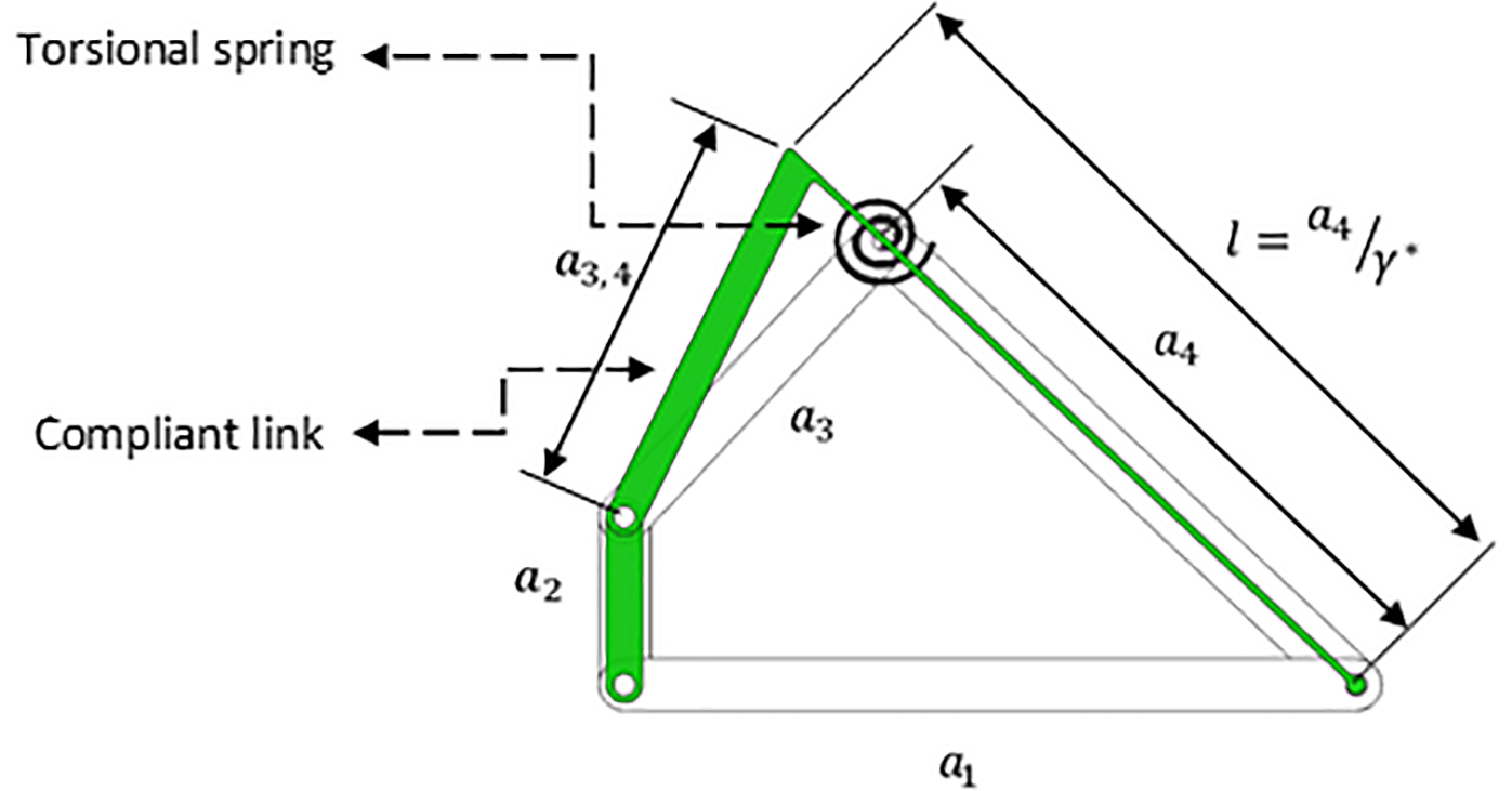
By using the rigid mechanism dimensioned in Sect. 2, we start the replacement synthesis. First, we need to draw the PRBM to scale (Fig. 8). As discussed in Sect. 2, an angle between a3 and a4 of 90∘ is used for the PRBM. The compliant segment of the compliant mechanism is overlapped with link 4 of the PRBM so that the initially straight beam lays on the revolute joints of a4. The length of compliant segment l is determined by using the characteristic radius factor γ* (Howell, 2001), as in Eq. (5):
The characteristic radius factor γ* is determined as follows: the compliant segment of the mechanism can be modeled as shown in Fig. 7. Here, the fixed side of the beam is the rigid segment of the compliant link, and the force F is the reaction force of the revolute joint between the fixed link (a1) and the compliant link.
The characteristic radius factor γ* is a function of n, i.e., the ratio between the horizontal and vertical components of the beam-end-force, F, as shown in Fig. 7. The force is a non-follower force, and, as this compliant link moves in a circular path, n is not constant (Howell, 2001).
There is a near-linear relationship between θ0 and Θ that is defined as (Howell, 2001)
As Θ is selected as 30∘ in Sect. 2, we can determine θ0:
where constant cθ is the parametric angle coefficient equal to 1.244 (Howell, 2001).
In order to simplify the design procedure, an average γ* value can be obtained, with an error less than 0.5 % (Howell, 2001).
By substituting Eq. (8) into Eq. (5), the flexible link length is calculated:
Flexibility of a compliant link increases by maximizing the Syield∕E ratio (Howell, 2001). Also, strength of the material must be sufficient enough to resist the stress due to large deformations. Furthermore, availability and cost are important factors in material selection. For the initial estimations, AISI 1080 steel (spring steel), which satisfies the above considerations, is chosen. Basic mechanical properties of this steel include Syield=880–1080 MPa, Sut=1170–1440 MPa, and E=210 GPa (tempered at 315 ∘C, and oil quenched) (Ashby, 2005).
5.1 Dimensional optimization
The pressing force required for an efficient sweeping should be determined prior to starting the wiper arm design. To this end, wiper arm pressing forces are measured on different vehicles, using a force gauge. The obtained pressing forces are divided by the length of the respective wiper blades, giving an average pressing force of Funit=0.22 N cm−1. By choosing a 70 cm wiper blade (optimized in Sect. 2.3) that is suitable for the windscreen used in this study, the required pressing force is
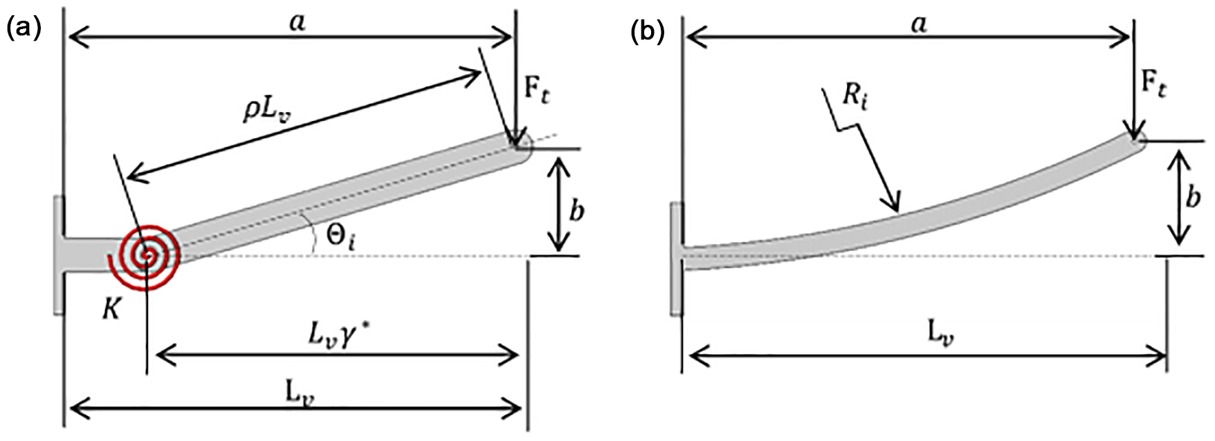
In conventional wipers, pressing force is generated by a helical spring. As in this study, the wiper pressing force is obtained by the curved segment as described in Sect. 1; radius of curvature and cross section of the beam should be determined. The wiper pressing force, Ft, which is generated by the curved beam, is the required force, and an iterative solution method is applied. The wiper pressing arm is normally at rest in a horizontal position, as shown in Fig. 9. In this horizontal position, the wiper pressing arm should apply a constant Ft perpendicular to the windscreen. The PRBM of the curved beam is shown in Fig. 9a. The torsional spring, with a spring constant K, provides the required pressing force, determined by the value of Θi.
As can be seen from Fig. 9a, Eq. (11) defines the moment equilibrium between wiper pressing force Ft and torsion from the torsional spring, about the pivot point. The torsional spring constant is defined as (Howell, 2001)
and the radius of curvature, Ri, can be determined as
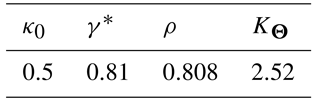
where E is the modulus of elasticity of steel; I is the moment of inertia of the beam; KΘ is the stiffness coefficient; Lv is the wiper pressing arm length (where the beam is initially straight) that was determined as 320 mm in Sect. 2.2; ρ is used as a characteristic radius factor in place of γ*, as γ* is valid for initially straight beams; ρ is a function of γ*; and κ0 is a nondimensionalized parameter that relates the initial curvature and the length of the beam. These values are presented in Table 1 (Howell, 2001).
Substituting the parameters given in Table 1 into Eqs. (11)–(13), the wiper pressing arm dimensions are determined by trial and error:
where h and w are the thickness and the width of the wiper pressing arm, respectively.
As the wiper pressing force is perpendicular to the beam, the maximum stress is given as (Howell, 2001)
By substituting the necessary values into Eq. (14), σmax=246.4 MPa, which is approximately one-fourth of the yield stress limit of the material.
5.2 Analytical stress calculation of the flexible segment
According to Fig. 7 and Eq. (9), the horizontal beam end coordinate is calculated as (Howell, 2001)
During the stress calculations, it was observed that the horizontal component of the force (nP in Fig. 7) yields a negligible amount of stress for the full cycle of the mechanism. Therefore, in order to simplify the solution, we neglect the horizontal component of this force, which yields n=0. The force that causes the deformation on the compliant segment is given in Eq. (16) (Howell, 2001):
where Bx and By are horizontal and vertical reaction forces at the bearing (O4 at Fig. 3) of the compliant segment, respectively.
From Eqs. (15) to (16) and the bending stress formula, the critical stress on the compliant segment is
where b and t are the width and thickness of the compliant segment, respectively. By using Eq. (17), flexible segment thickness and width are determined iteratively, corresponding to the strength of the material. From this, the link cross-sectional dimensions are determined as t=1 mm, and b=30 mm. With these dimensions, the stress of the flexible segment remains in an acceptable range for the complete cycle. The resulting stress values with respect to angular position of the input link (θ12) are presented in Fig. 10. The determined maximum and minimum stresses are ∓311.2 MPa.
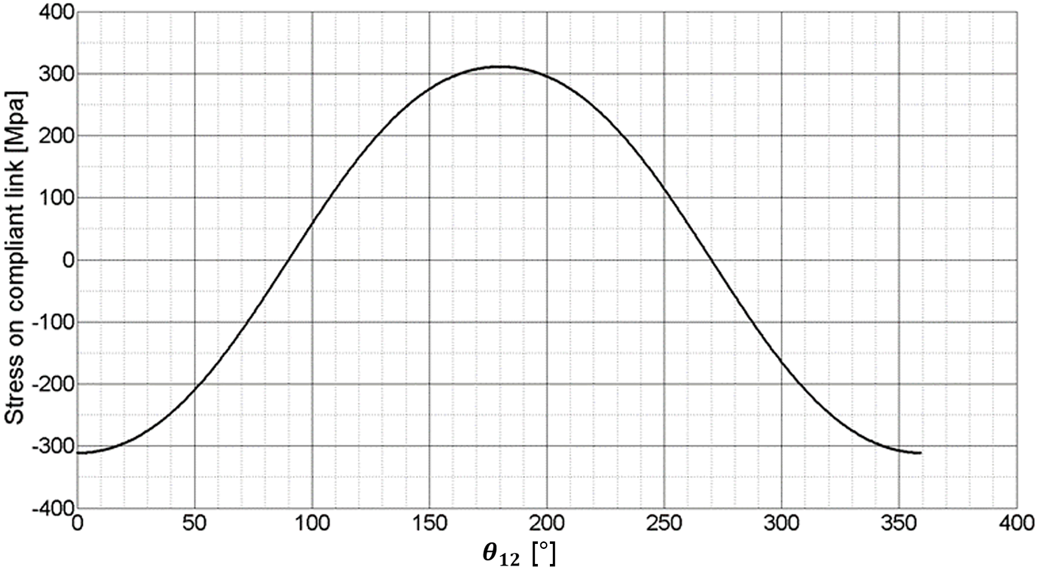
Figure 10Stress variation for compliant link (link 4) with respect to crank (link 2) position.
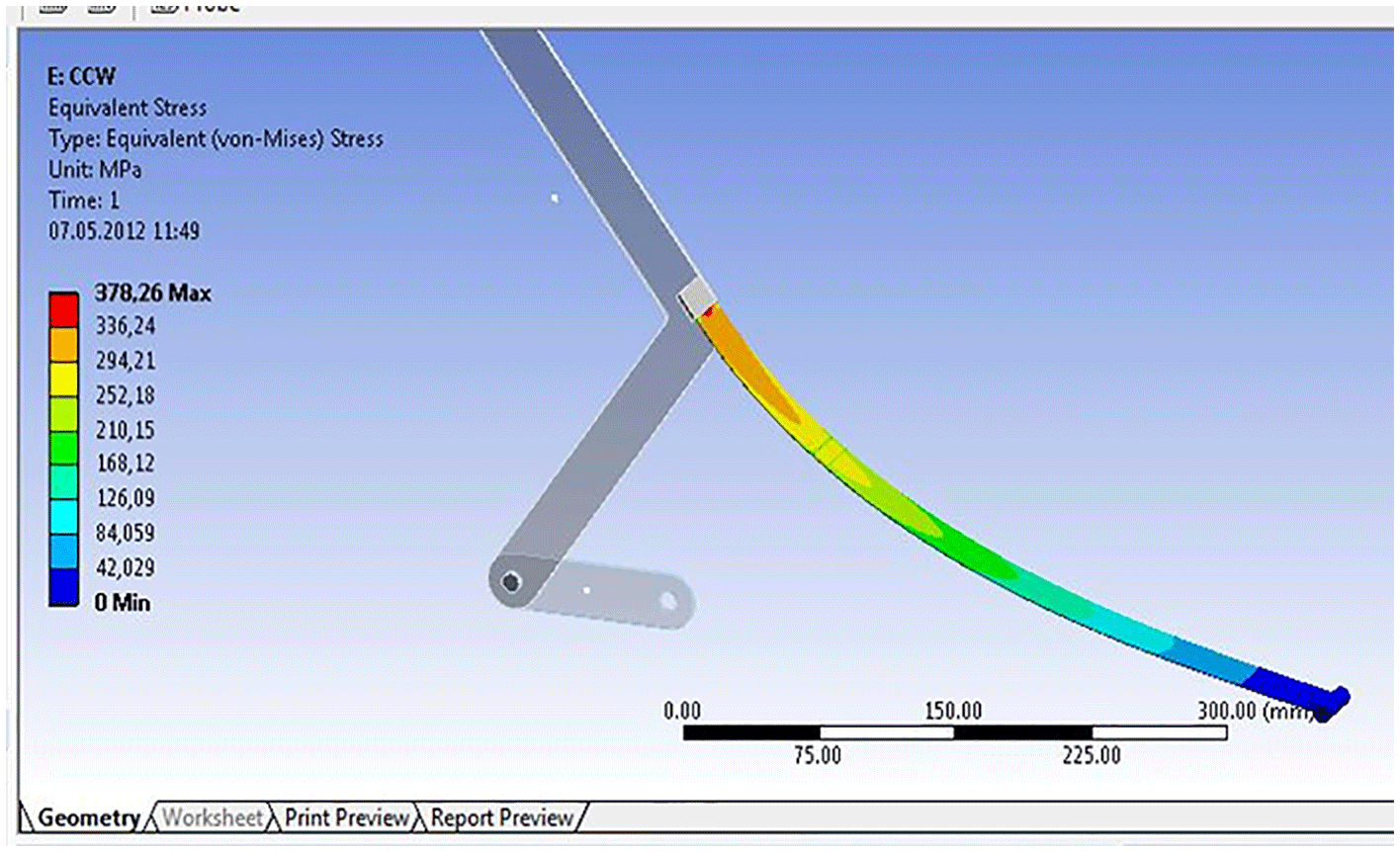
5.3 Stress analysis using the finite element method
In order to verify the analytical approach, FEA is performed and equivalent stresses on the compliant link are determined. The results are shown in Fig. 11. Neglecting the stress concentration regions, the maximum stress is determined as σmax=336.2 MPa. This result is in agreement with the analytically calculated stress.
5.4 Life estimation of the mechanism
Fatigue failure can occur at stresses that are significantly smaller than those causing static failure. Therefore, a fatigue life analysis is essential for all compliant mechanisms. Furthermore, as this mechanism will be used in automotive applications, the fatigue life is critical. The unmodified endurance limit (for the fatigue test specimen), which is the point where failure will not occur regardless of the number of cycles, for this steel is , Sut=655 MPa (Budynas and Nisbett, 2011). The endurance limit of the fatigue specimen tests must be modified according to the conditions of the actual components. To determine these conditions, Marin factors (Budynas and Nisbett, 2011) are used, the most important of which is surface finish. Although the surface finish factor is taken as unity for polished machine parts, there may be some small scratches on the surface of the supplied sheet steel. Therefore, in order to be conservative, this factor is taken as ground, with ka=0.87. Increasing the dimensions of machine parts also increases the probability of imperfection on the surface. In this case the size factor (Budynas and Nisbett, 2011) is taken as kb=1.02. As the test specimen is subjected to a completely reversed loading, the load factor (Budynas and Nisbett, 2011) is taken as kc=1. The mechanism will be tested at room temperature; thus, the temperature factor (Budynas and Nisbett, 2011) is taken as kd=1. The data on endurance limit versus tensile strength are scattered, and the majority of the endurance strength data are taken as mean values. For 99.9 % reliability, the reliability factor is taken as ke=0.753. Finally, the miscellaneous-effect factor (Budynas and Nisbett, 2011) is taken into account as stress concentration only, and is taken as kf=0.8. The modified endurance limit Se can be calculated as
As the designed mechanism has a cyclic working principle, a life estimation calculation is essential. The required life is greater than 1 million cycles to ensure robustness of the compliant wiper mechanism. According to the Woehler strength-life diagram, for completely reversed loading, the number of cycles (N) where failure occurs can be calculated as follows (Budynas and Nisbett, 2011):
where the loading type (cf) is bending, and thus cf=0.9.
The critical stress determined by the FEA is
From Eqs. (18) to (22), N is calculated as 1.237×10⁶, i.e., greater than 106. This number indicates an infinite life for steel in the Woehler strength-life diagram (Budynas and Nisbett, 2011).
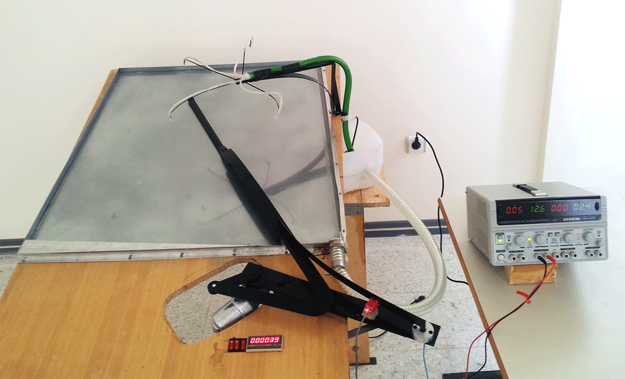

For compliant mechanisms, it is required to build a prototype and perform tests under realistic conditions. These tests are essential to verify the theoretical approaches. A prototype of the dimensioned mechanism was manufactured, and the parts were manufactured using basic workshop machines such as a drill, sheet metal shear, and lathe. The manufacturing tolerances were set to ∓0.1 mm. The coupler and rocker were built from a single piece of sheet steel; these links were manufactured separately and assembled. Other components of the test setup are a windscreen model, a water circulation and spraying system, an actuator motor, a proximity sensor, and a cycle counter.
First the maximum deflection of the compliant segment was measured. It can be observed from Fig. 13 that the maximum deflection of the compliant segment is very close to the value that was calculated theoretically in Sect. 3.
The fatigue tests, under continuous water spraying conditions, were then conducted. During the first experiment, the spot-welded connection between the compliant segment and the coupler link (Fig. 1) failed at a low cycle. Investigation of this failure indicated that the spot welding caused a deterioration in the structure of the material that caused a significant decrease in the fatigue strength of this part. The connection between the compliant segment and coupler link was redesigned by using the sandwiching method by bolts. This design also eliminated the stress concentrations at the edges. Following this modification, the prototype successfully completed over 1.1 million cycles, which means infinite life for a part manufactured from steel (Budynas and Nisbett, 2011). Furthermore, the wiper blade pressing arm was still applying satisfactory pushing force. This test proved that the proposed compliant wiper mechanism, which is sweeping an acceptable area, also has infinite life under realistic conditions. This result is in agreement with the theoretically calculated lifespan from Eqs. (18) to (22). The results indicated that an infinite life can be achieved with this design. Also, theoretical deflections are verified with experimental results.
The video link of the test setup is presented in Appendix A.
In this study, a novel compliant wiper mechanism was introduced and studied, and a design methodology was proposed. After the theoretical calculations, a prototype was manufactured and an experiment was set up. The data obtained from the experimental setup were compared with the theoretical results. The amount of deflection of the compliant link and the force applied by the wiper pressing arm were measured, and the endurance of the mechanism was tested. It was observed that the theoretical and experimental results were in close agreement. It was also verified that the proposed compliant mechanism has an infinite lifespan under specific conditions.
The number of parts in a conventional wiper mechanism is significantly reduced with the compliant wiper design. The reduction in the number of parts yields a decrease in cost and assembly time. Especially in the automotive industry, cost reduction is one of the most important requirements. Also, reducing the number of rigid joints increases the precision of the mechanism, because backlash can be decreased.
On the other hand, compliant wiper mechanisms have some drawbacks, especially during design stages. The design procedure is a composition of different optimization studies with numerous parameters. Fatigue of the compliant wiper link is a serious issue. An attentive theoretical and experimental procedure should be carried out in order not to come across with a catastrophic failure. These design difficulties cost a considerable amount of time and design procedures require knowledge of mechanism analysis–synthesis methods and large deflection analysis.
In summary, with this study, it was shown that replacing a conventional rigid wiper mechanism with a partially compliant one is feasible. We believe that our novel compliant wiper mechanism can be a good alternative to rigid versions that are already available on vehicles.
Data can be made available upon reasonable request. Please contact Engin Tanık (etanik@hacettepe.edu.tr).
The video file of the prototype is available at https://youtu.be/ZU-Qtec59eA, last access: 2 October 2018.
ET proposed the original design and defined the methodology. RK applied the methodology and developed solutions.
The authors declare that they have no conflict of interest.
Edited by: Doina Pisla
Reviewed by: two anonymous referees
Alt, V.: Der Übertragungswinkel und seine Bedeutung für das Konstruieren periodischer Getriebe, Werkstattstechnik, Berlin, Germany, 1932. a
Ashby, M.: Materials Selection in Mechanical Design, Elsevier, Oxford, UK, 2005. a
Balli, S. and Chand, S.: Transmission angle in mechanisms (Triangle in mech), Mech. Mach. Theory, 37, 175–195, 2002. a
Brodell, R. J. and Soni, A.: Design of the crank-rocker mechanism with unit time ratio, J. Mechanisms, 5, 1–4, https://doi.org/10.1016/0022-2569(70)90047-9, 1970. a, b
Budynas, R. and Nisbett, J.: Shigley's Mechanical Engineering Design, McGraw Hill, New York, USA, 2011. a, b, c, d, e, f, g, h, i
Cao, L., Dolovich, A., and Zhang, W. J.: On understanding of design problem formulation for compliant mechanisms through topology optimization, Mech. Sci., 4, 357–369, https://doi.org/10.5194/ms-4-357-2013, 2013. a
Fowler, R. M., Howell, L. L., and Magleby, S. P.: Compliant space mechanisms: a new frontier for compliant mechanisms, Mech. Sci., 2, 205–215, https://doi.org/10.5194/ms-2-205-2011, 2011. a
Howell, L.: Compliant Mechanisms, John Wiley & Sons, Inc., New York, USA, 2001. a, b, c, d, e, f, g, h, i, j, k, l, m, n, o
Lan, C.-C.: Analysis of large-displacement compliant mechanisms using an incremental linearization approach, Mech. Mach. Theory, 43, 641–658, 2008. a
Lobontiu, N.: Compliant Mechanisms Design of Flexure Hinges, CRC Press, Boca Raton, FL, USA, 2002. a, b
Tanık, E.: Transmission angle in compliant slider-crank mechanism, Mech. Mach. Theory, 46, 1623–1632, 2011. a, b
Tanık, E. and Karakus, R.: A compliant wiper mechanism, Patent : Turkish Patent and Trademark Office, TR 2013-10617, Ankara, Turkey, 2013. a
Tanık, E. and Parlaktaş, V.: Design of a very light L7e electric vehicle prototype, Int. J. Automot. Techn., 16, 997–1005, 2015. a, b
Venanzi, S., Giesen, P., and Parenti-Castelli, V.: Erratum to “A novel technique for position analysis of planar compliant mechanisms” [Mech. Machine Theory, 40 (2005)1224–1239], Mech. Mach. Theory, 45, 811, 2010. a