the Creative Commons Attribution 4.0 License.
the Creative Commons Attribution 4.0 License.
 | 28 Aug 2018
Mechatronic design and genetic-algorithm-based MIMO fuzzy control of adjustable-stiffness tendon-driven robot finger
Izzat Al-Darraji
Ali Kılıç
Sadettin Kapucu
This work presents a detailed design of a three-jointed tendon-driven robot finger with a cam/pulleys transmission and joint Variable Stiffness Actuator (VSA). The finger motion configuration is obtained by deriving the cam/pulleys transmission profile as a mathematical solution that is then implemented to achieve contact force isotropy on the phalanges. A VSA is proposed, in which three VSAs are designed to act as a muscle in joint space to provide firm grasping. As a mechatronic approach, a suitable type and number of force sensors and actuators are designed to sense the touch, actuate the finger, and tune the VSAs. The torque of the VSAs is controlled utilizing a designed Multi Input Multi Output (MIMO) fuzzy controller. The fuzzy controller input is the force sensors' signals that are used to set the appropriate VSA torque. The fuzzy controller parameters are then tuned using a genetic algorithm as an optimization technique. The objective function of the genetic algorithm is to avoid unbalance torque in the individual joints and to reduce the difference between the values of the supplied VSAs torques. Finally, the operation of the aforementioned finger system is organized through a simple control algorithm. The function of this algorithm is to enable the detection of the unknown object and simultaneously automatically activate the optimized fuzzy controller thus eliminating the necessity of any external control unit.


The evolution and development of the robot hand has played a strategic role in the robot revolution as it is essential in numerous different applications such as service robots. Researchers continue to improve the performance of the robot hand through innovative and creative design together with the careful selection of suitable control algorithm in conjunction with the used sensors and actuators. A tendon-driven mechanism is being suggested in several robot hands due to its essential properties of: (1) driving the motion of the fingers by wire cables similar to the muscles of real human hands; (2) generating the required tension to actuate the finger by motors in the base of the hand rather than the joints of fingers which has enabled a reduction in finger size; and (3) having low coefficient of friction, mass, and backlash (Kino et al., 2004). In finger manipulators, the large difference between the contact forces on the phalanges results in damage to the grasped objects. The geometry design of finger mechanism parts using kineto-static analysis is presented as a solution to reduce the varying contact forces on phalanges. The feature of providing close values between the contact forces is referred to as force isotropy. Force isotropy is an essential property that the finger requires in order to avoid stress concentration which causes damage to the grasped objects during contact. Krut (2005) presented a design theory study of an underactuated finger with 2 degree of freedom. Krut suggested a cam-tendon configuration in his approach to obtain force isotropy. Achieving force isotropy in a full grasping operation wasn't taken into consideration and it is mentioned as a future work. Dandash et al. (2011) introduced a technique to achieve force isotropy property for underactuated fingers of three phalanges. Dandash used cam-tendon mechanism again as in Krut (2005) taking a full grasping operation into consideration. As a future work, Dandash et al. recommended to produce the suggested mechanism practically. Rizk (2007) introduced a technique to design a three-phalanx underactuated mechanism of two pairs of curved gears to achieve force isotropy. The kineto-static analysis is applied to achieve an isotropic finger. The analysis of the suggested mechanism showed a typical isotropy between the intermediate phalanx and the distal phalanx. Producing the introduced mechanism practically is suggested as a future work. On the other hand, when used in grasping applications, conventional tendon-driven mechanisms have the disadvantage of a relatively poor grasping ability. For instance, a simple actuating tendon finger has a low grasp forces (Birglen et al., 2008) which restricts the holding of relative heavy objects, or preventing objects from falling when the robot hand moves at a relative high speed. Compliant mechanisms have been suggested by researchers as a solution to enhance the grasping performance of tendon-driven mechanisms. Bundhoo et al. (2009) developed a novel artificial finger using compliant tendons and wires made from a type of shape-memory-alloy. They suggested a compliant tendon which is constructed using a spring-slack component with integrated shape memory alloy wires. This compliant mechanism provided the finger with the ability of work similarly to a natural finger with real muscles. These muscles represented the agonist-antagonist pairs during flection and abduction of the proximal phalanx and the flection of the intermediate phalanx. Ozawa et al. (2009) introduced a new hybrid mechanism of passive and active tendons to improve the function of a two-linked finger in such a way that the produced finger could mimic a real finger configuration during the contact process. This mechanism contained three tendons. The first tendon was active while the others were passive. The drawback of this mechanism was the disability of generating high torque approaches. Later, in a proceeding work, Ozawa et al. (2014) introduced the design of a new robot finger which has real finger characteristic feature of absorbing environment forces during contact process. The presented mechanism included six tendons. It contained two passive type tendons which are arranged in a special way between the tip of distal phalanx and the intermediate phalanx and the remaining four were active tendons. In and Cho (2013) introduced a finger mechanism whose primary characteristics are a fast closing sequence and large contact forces during the grasp phase. The aforementioned two features are accomplished by integrating an adjustable arm element with a tendon driven mechanism. The tendon driven mechanism has a variable transmission ratio which varies with respect to the varying of the moment arm element. The moment of the arm element is specified by the manner in which it is mounted along the path of wire and the joint. Through a two-finger gripper design and development of envelope grasping, Ciocarlie et al. (2013) established a stable grasping operation for large objects. The introduced mechanism applied active flexor tendon, joint spring, and extensor tendon. The functionality of the gripper is accomplished by optimizing the path of the active flexor tendon. Furthermore, the applied passive springs supplied the extended force. Kuo et al. (2015) designed a novel human like compliant finger through integrating compliant material in joints with a tendon routing. The geometry deign of the compliant materials provided the designed finger the functionality of compliance behavior like the joints of human hand. The tendon routing is arranged in a similar way to the real human finger. As a result, the finger had robustness during the grasping and manipulation operation. In control view, fuzzy logic algorithm with tendon-driven robot hands have been implemented to control underactuated mechanisms. Hristu et al. (1994) controlled an underactuated multi-fingered robot hand using fuzzy algorithm and compared the results with tradition Proportional Integral Derivative (PID) controller. The introduced study included discussion of both the position of joints and force of touching sensors. In not combined position and force control, the results showed that the performance of the fuzzy controller was better that the PID controller. In control of hybrid position/force behavior, Hristu et al. (1994) showed that an extra procedure is needed to tune the parameters of the hybrid fuzzy controller in order to overcome the problem of weighting between commands of position and force. Birglen and Gosselin (2005) used fuzzy logic controller to control underactuated finger. The tactile and position information are used in the implemented fuzzy controller. The results showed that an enhanced force control can be obtained using fuzzy controller where the underactuated finger could hold a fragile object with a real human finger and get about it with a grip approach.
Additional actuators enhance the stiffness of grasping and contact forces in underactuated fingers (Boucher and Birglen, 2017). The Variable Stiffness Actuator (VSA) provides compliant actuation via springs in such a way they decouple the inertia of motor which adjusts the stiffness from the output link. The first idea for a VSA dates back to 1995 and is associated to Pratt and Williamson (1995). They located a series elastic actuator between the motors output (stiff actuator) and the link output. In this way, the force can be easily controlled. The stiffness adjusting for the series elastic actuator was later achieved by an updated mechanism called a VSA (Wolf et al., 2016). Variable stiffness has essential impact on the performance of underactuated fingers. Aukes et al. (2011) developed a robot hand that has the essential property of accommodating both large and small objects. The internal forces of grasping are balanced by adjusting the preload of the applied compression spring. An adjustable screw is connected in series with this compression spring. Then, the spring-screw mechanism is positioned in two opposite locations in such a way that the four bar linkage finger adopted a range of poses during grasping. On the other hand, Fumagalli et al. (2016) integrated a mechanism of VSA with underactuated finger. Thus, the grasped forces are adjusted by varying the stiffness of VSA. An important factor in the VSA control is how to manage the stiffness, as its value varies according to the external force. Some control algorithms are applied to optimize values of stiffness for optimizing task performance, while the others are applied to compute the motor position commands and the associated time-varying torque with stiffness profiles. Albu-Schäffer et al. (2010) designed a simple gain scheduled state feedback controller for a new two joints variable compliance arm. The applied control algorithm is based on vibration damping. Adjusting the mechanical damping via the suggested control method treated the problem of both the low damping springs and the high tuning of VSA stiffness. Palli and Melchiorri (2011) presented the control of the force interaction with the environment of an adjustable joint stiffness robot manipulator. It is assumed that the interaction force is not directly measurable, but the proposed controller can estimate the force. Also, the problem of simultaneous control of both the position and the stiffness trajectory in the robot workspace is investigated. Braun et al. (2012) proposed an optimal control formulation to a compliant robotic. The motor position commands and the associated time-varying torque with stiffness profiles are computed optimally. As a result, the optimal stiffness of VSA is obtained based on the dynamics of the compliant robot system. Then, the optimal stiffness is applied to independently check the control advantage between stiffness and torque.
This paper examines the grasping mechanism in existing VSAs joints and tendon-driven actuating with the objective to control firm grasp. We have analytically and experimentally investigated a prototype robot hand called as Cam Pulley Robot Hand (CPRH) with two identical fingers called a Cam Pulley Robot Finger (CPRF). The aim of this work is to treat the low grasp forces problem using a suggested mechanism of VSA which is integrated with a tendon-driven mechanism. The geometric design of the tendon-driven mechanism is derived mathematically to regulate the motion of the joints together in a special order to achieve isotropic force on phalanges. Hence, the designed finger has close contact forces by phalanges on the grasped objects with the essential particularity that grasp forces on the phalanges can be improved and adjusted by tuning the stiffness matrix of the VSAs. The VSAs are designed in the joints to enhance the property of grasping by increasing the torque in the joints through a fuzzy logic controller. The fuzzy logic controller is a MIMO who's inputs and outputs are the force signals on the phalanges and the torque of VSAs, respectively. The performance of the fuzzy controller is optimized using genetic algorithm in order to reduce the large difference between the values of VSA torque which can cause damage to the grasped objects. The VSAs adjust their torque once the finger has detected the grasped object and has stopped its motion. This is essential to ensure that the VSA will not affect the motion of the designed tendon-driven mechanism. Specifically, a control algorithm is carried out to synchronous the operation of the mentioned mechanical parts, electronic hardware, and the fuzzy logic controller. This algorithm is written in a simple way such that it: stops the motion of the finger when it detects objects, and activates the fuzzy logic controller to support appropriate VSA torque during the grasp phase. Finally, the suggested finger mechanism also facilitates actuating both the motion of the finger and the VSA by mounting motors in the fixed part under the palm. This is essential in a robot hand to reduce the finger size.
This paper is organized as follows: In Sect. 2, details of producing CPRF with deriving mathematical equations of the model are introduced. Next, in Sect. 3, the description of the layout and the hardware architecture of the sensors and actuators are explained along with the assembly of the prototype robot hand. Section 4 shows the designed fuzzy logic controller, the optimized genetic algorithm, and the applied control algorithm. In Sect. 5, the performance of the designed prototype is presented in tests. In Sect. 6, the results of this work are discussed. Finally, in Sect. 7, concluding remarks are made and the possible direction of the future research are stated.
2.1 CPRF Mechanism
Two distinguishing stages exist in the grasping operation. The first is the planning stage. This period starts from the non-contact position until the moment where the finger comes into contact with the grasped object. The second one is the holding stage, which is responsible for holding the object by applying appropriate forces between the object and the finger on contact points (Buss et al., 1996). The proposed CPRF has accomplished the aforementioned two stages thanks to the design of the finger mechanism. In general, the mechanism contains three links of three joints who's angles change relatively to each other by a tendon-driven mechanism in the planning stage. The proposed VSA mechanism is placed on the other side of each joint to act as an actuator of variable stiffness to improve the grasping forces on phalanges for the holding stage.

2.1.1 Tendon-driven Mechanism
The tendon-driven mechanism is implemented to achieve force isotropy in the planning stage by using cams instead of pulleys. This tendon-driven mechanism is shown in Fig. 1a where pulley 1 is free to rotate of radius r1, and pulley 2 is a double type free to rotate of radii r2 and r3, while the third one has a radius r4 which is fixed to link (BC). Actuating the tendon, by rotating a motor in a clockwise direction, results in rotating the three links relatively during closing motion to grasp an object. Opening motion occurs by rotating the same motor in an anticlockwise direction due to the effect of tension springs of stiffness (K1′, K2′, K3′) shown in Fig. 1a. The relation between the lengths of finger links is set based on a real human finger. In a human finger, the mean length of the proximal phalanx approximately the sum of the lengths of intermediate phalanx and distal phalanx (Rodríguez, 2006). Thus, the relation between the lengths of CPRF links becomes as;
where l1, l2, and l3 are the length of link (OA), link (AB), and link (BC), respectively. Consequently, golden ratio ϑ is used here to calculate the ratio between the lengths of two consecutive links (Rizk, 2007; Dandash et al., 2011; Ask, 2016);
assuming that the phalanges contact the object along their entire length. Hence, the pressure, i.e. the pressure produced by contact forces on the length of finger links, is; To add a, b, c to the numbering:
where b is the width of the finger. In order to get a uniform contact pressure during grasping, Eq. (3a, b) is equalized. In this way;
from Eq. (2), the ratio between l1 and l2 is;
hence, Eq. (4) becomes;
also, Eq. (3b, c) is equalized to get a uniform contact pressure. Thus;
from Eq. (2), the ratio between l2 and l3 is;
hence, Eq. (6) becomes;
Supporting distributed pressure on the grasped object, to avoid the damage to the grasped object, is achieved by considering the force isotropy between contact forces in Eqs. (5) and (7). These two equations are used later in the geometry design of finger in Sect. (2.2) to enable the configuration motion of finger contact the grasped object with force isotropy property.
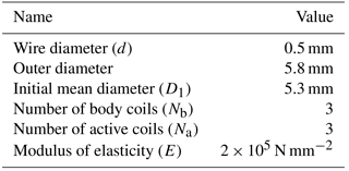
Table 1Physical properties for the torsion spring of material stain steel.
2.1.2 VSA Mechanism
The basic idea of the suggested VSA mechanism is obtained from the design equations of torsion spring. A torsion spring of properties listed in Table 1 is mounted on the joint shaft (O: MCP joint, A: PIP joint, and B: DIP joint). If one of its ends is fixed with the link of the robot finger and the other end is free to rotate through a pulley as shown in Fig. 1b, by changing the angle of the pulley by tendon through a motor, the mean diameter Dm of the spring is reduced according to the following equation (Shigley and Mischke, 2004);
assuming i the index of joint (where ), the stiffness rate per degree is changed;
where Δθ is the difference between the angle θ of the link and the free end side of the torsion spring θ′ shown in Fig. 1b. The link is considered fixed because in the control approach the stiffness of the VSA is adjusted only in the hold position. During change the stiffness, the supplied torque by VSA at each joint becomes;
Hence, tuning the stiffness of VSA gives rise to a corresponding torque as shown in Fig. 2.
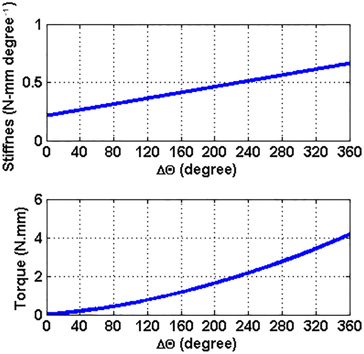
Figure 2Supplied torque by VSA corresponding to the change of stiffness with respecting to the deflection.
2.2 CPRF Design
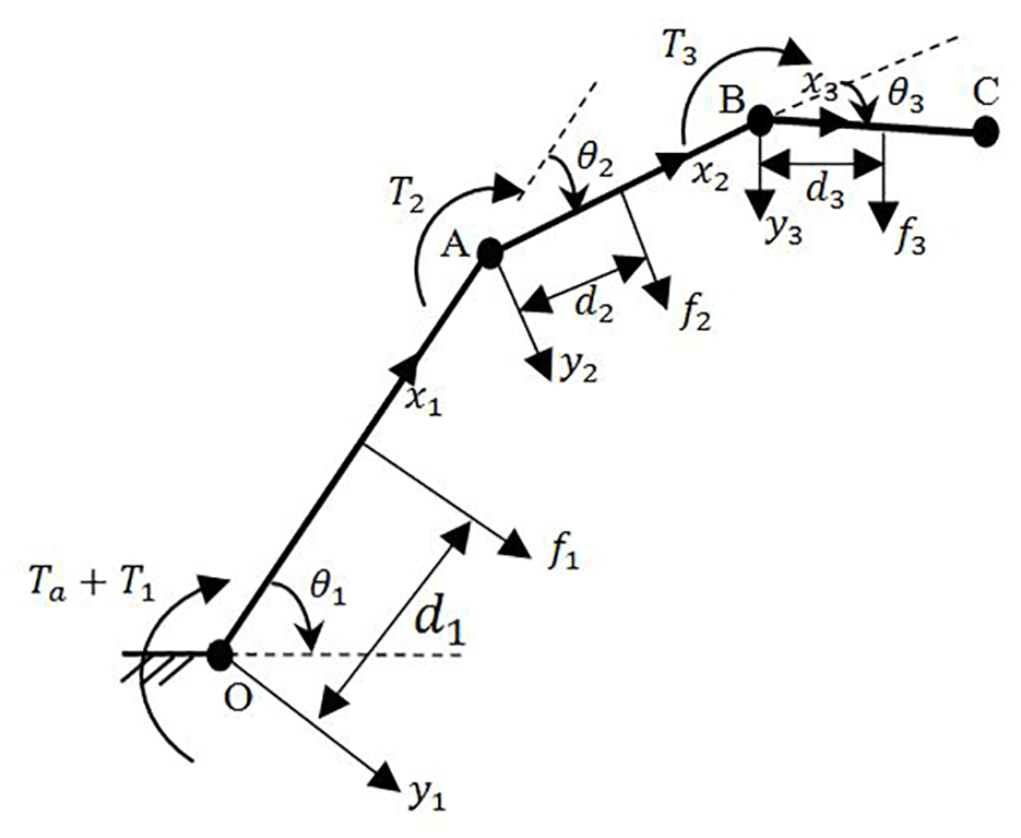
Geometric model of Fig. 1a with input and output forces is presented in Fig. 3 and its parameters are detailed in Table 2 (where . Geometric parameters of mechanism parts are set to avoid undistributed contact forces on phalanges. Specifically, in the kineto-static analysis, contact forces are derived here from the input and output powers of the CPRF. Then, these contact forces are substituted in Eqs. (5) and (7) in order to find the relations between radii of pulleys which achieve force isotropy. Next, some pulleys are replaced with cams so that the relative motion between phalanges is regulated to reach the grasped object with close contact forces. Finally, the profile of cams is obtained by some mathematical calculations.
Let Pin and Pout denote the input and output power to the robot finger, respectively. These powers are obtained as;
where
equalizing Eqs. (11) and (12), contact forces become;
where


The springs in the tendon-driven mechanism have low stiffness when all phalanges make contact with the grasped object, compared with the actuation torque. In addition, the actuation torque has to remain constant to have an isotropic design. Therefore, the action of the springs is negligible in the kineto-static analysis of tendon-driven mechanisms (Krut, 2005; Birglen et al., 2008; Dandash et al., 2011). By ignoring the effect of springs, the contact forces in Eqs. (13–15) become;
substituting Eqs. (17) and (18) into Eq. (7), to find the relation between radii that gives force isotropy, yields the ratio between r3 and r4;
the above equation maps the profile of cam 4. For a constant radius r3, the profile of cam 4 is obtained by geometrical analysis of Fig. 4 with some calculations. Assuming;
and rearranging Eq. (20) in term of Q, we obtain;
from Fig. 4, β is;
substituting Eq. (20a) in this formula, yields;
selecting the vector u parallel to the tendon path between points (H3H4) and the vector v parallel to the path between point (H4) and joint (B), we get;
assume J an arbitrary point on the tendon, then;
using the vectors in Eq. (22a–d), Eq. (26) becomes;
profile of cam 4 is determined by values of u that satisfies the following determinant matrix (Dandash et al., 2011);
the elements of the determinant matrix are obtained from Eq. (24a, b);
then, the determinant in Eq. (28) is calculated as follow;
rearranging the Eq. (29) in term of u, we get;
referring to Eqs. (20b) and (21);
In this way, the profile of cam 4 in Eq. (24a, b) is obtained as;
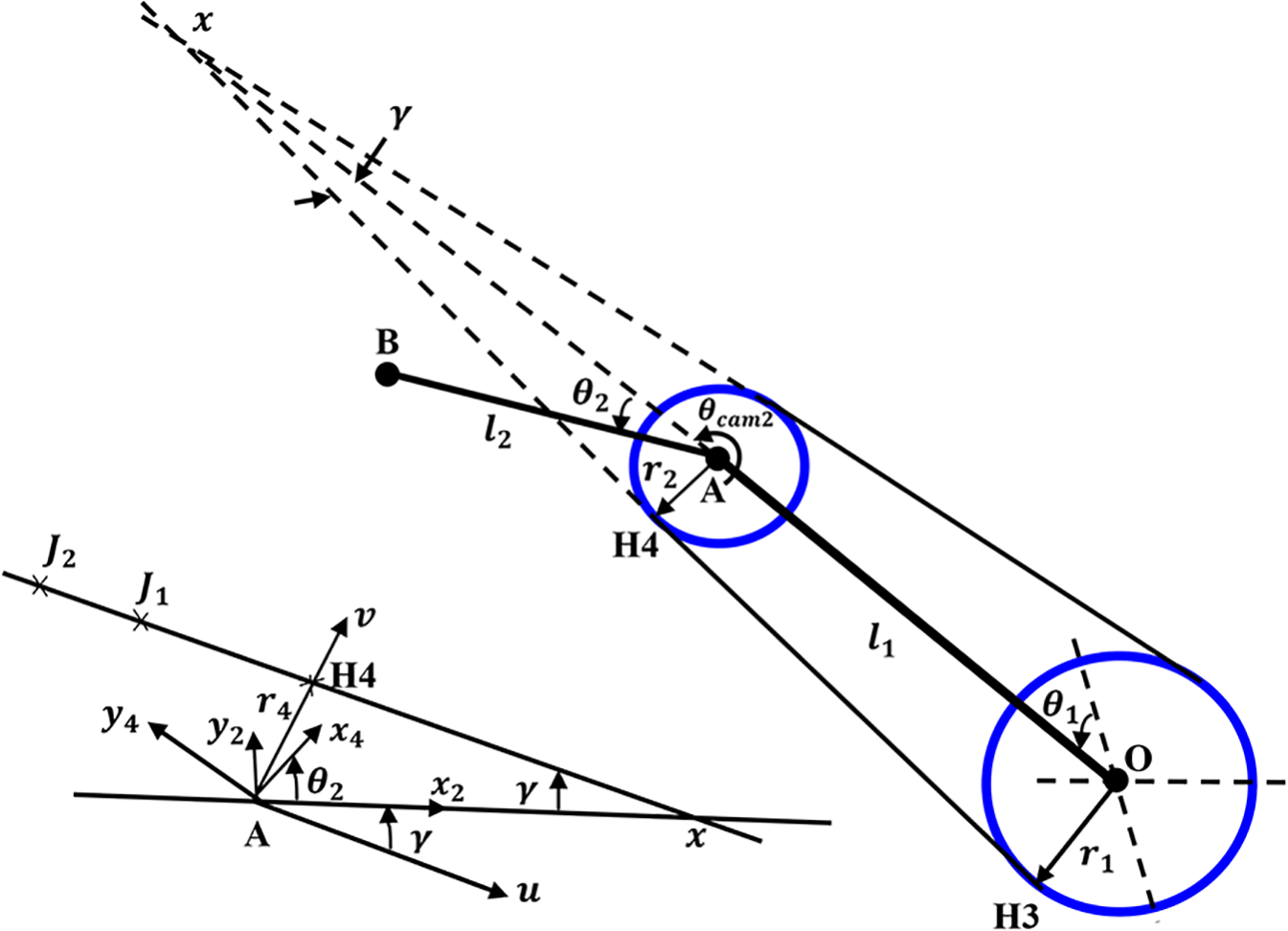
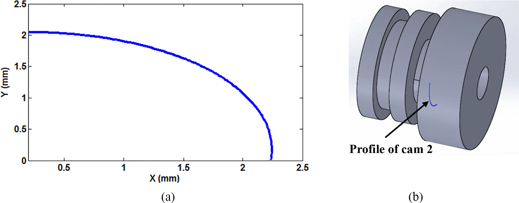
The next step is to obtain the profile of cam 2. Getting the profile of cam 2 is more complicated than cam 4 profile because cam 2 is free to rotate, while cam 4 is fixed to distal phalanx. Since cam 2 is free to rotate on the joint (A); therefore, we should find a relation between the free rotation of cam 2 and the rotation of link 2. Assuming cam 2 rotates with an angle θcam 2 as shown in Fig. 5, hence;
let;
then;
substituting Eqs. (16) and (17) into Eq. (5), to find the relation between radii that gives force isotropy, yields the ratio between r1 and r2;
where;
the ration between pulleys in Eq. (30) is a function of N1,
l1, l2, l3, θ2, θ3, and ϑ.
Eq. (30) maps the profile of cam 2. For a constant radius r1, the
profile of cam 2 is obtained by geometrical analysis of Fig. 5 with some
calculations as follows:
let;
then merging Eq. (31) with Eq. (30), yields;
and

As shown in Fig. 5, the angle between link (OA) and the tendon is;
let J1 the nearest point of the tendon to the joint (A);
let J2 be any point of the tendon;
then;
by applying the same procedure in deriving the path of cam 4, the profile of cam 2 is obtained by λ. Assume;
according to Eq. (35a, b);
substituting these two formulas in Eq. (36) and after calculating of the determinant matrix, we get;
to find and , r2 is obtained from Eq. (34);

thus;
according to Eq. (31);
hence;
referring to Eqs. (32) and(33);
now substituting Eqs. (38) and (39) in Eq. (37), yields;
Hence, cam 2 profile in Eq. (35a, b) is obtained as;

Figure 9CPRH System (a) Diagram of components (b) Hardware architecture of the electronic and drive system.
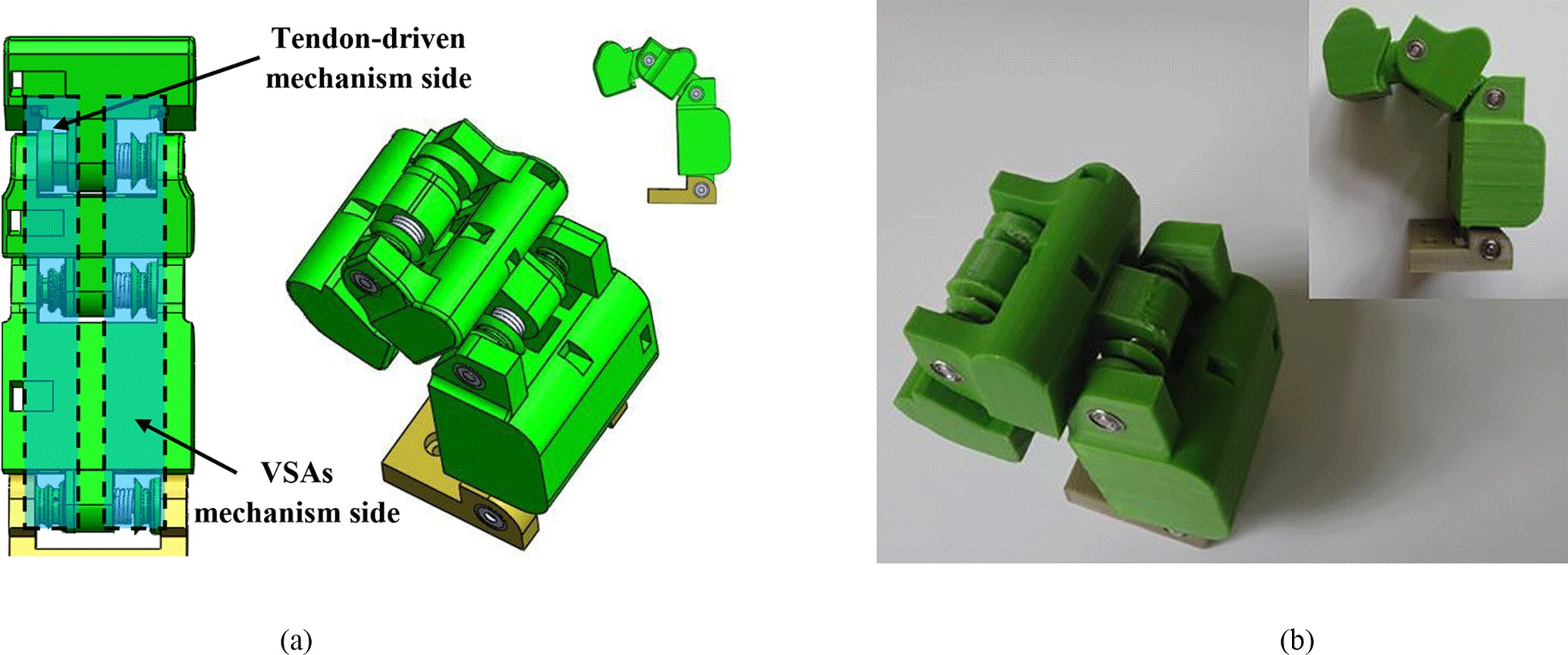
The profile of cam 4 from Eq. (27a, b) is calculated and designed in the CAD drawing as shown in Fig. 6 for a constant radius of pulley3 4 mm, maximum distal rotation angle 90∘, and length of link 1 (Proximal), link 2 (Intermediate), and link 3 (Distal) 50, 30.902, and 19.098 mm, respectively. The lengths of the intermediate and distal phalanges are calculated using golden ratio relation between links in Eq. (2) from the length of the proximal phalanx. On the other hand, the profile of cam 2 is calculated and also designed in CAD drawing by using Eq. (41a, b) as shown in Fig. 7 for pulley1 radius equal to 4 mm and radius of the basic pulley of cam 2 equal to 1.5 mm with maximum intermediate link angle of rotation 90∘. All the described parameters of design cam 2 and cam 4 are listed in Table 3. Implementing these numerical values and geometry design, the CAD of CPRF parts are drawn and assembled as shown Fig. 8a. Then, they are manufactured by a 3-D printer and assembled together with torsion springs to obtain the CPRF prototype shown in Fig. 8b.

3.1 Sensorimotor System
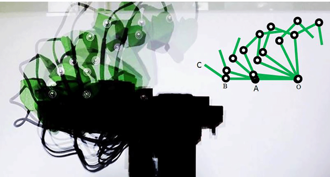
Figure 11Workspace of the designed CPRF for seven situations with 10∘ step between each one.
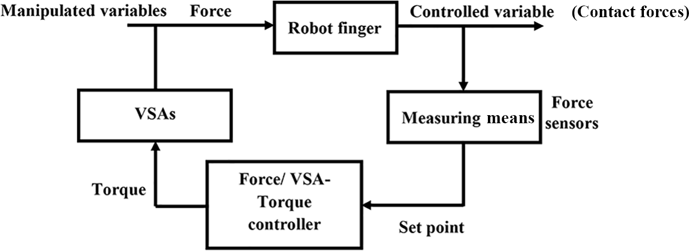
A suitable sensorimotor layout is proposed, designed, and programmed with its computer interface circuit to sense the grasped objects and actuate the mechanical parts of the designed CPRF in CPRH. The overall layout is shown in Fig. 9a, in which, the motor of the tendon-driven mechanism is controlled by force sensors which in turn adjust the stiffness of the VSAs. A Force Sensitive Resistor (FSR) sensor is used to sense touch on the phalanges. The sensor type (FSR 402 Short) of 15.24 mm diameter is applied for proximal phalanx and type (FSR 400 Short) of 6.35 mm diameter is applied for intermediate and distal phalanges (Pololu Force Sensing Resistor, 2018). The FSR sensor changes its resistance depending on the magnitude of the force applied to its surface. In order to be able to read the sensor signals, an electronic circuit is designed that pinned the analog signal from a voltage divider circuit of a resistance 10 kΩ to the Arduino 2560 microcontroller board analog signal pins (A0, … , A5). Additionally, the designed electronic circuit assists in producing more output changes with respect to fewer changes of FSR resistance to overcome the nonlinearity of FSR sensors. To obtain proper experimental data, it was important to calibrate the force sensors employed in the robot finger. For all FSR 400 series sensors used, obtaining force unit from the resistance of the sensor is implemented dependent on the number of analogue to digital converter (ADC) bits and voltage divider circuit. Using: (1) the Arduino 2560 microcontroller board of 10 bits; and (2) the range of mapping voltage between 0–5000 mV, we get;
where VFSR and Vanalog are the voltage across the FSR sensor and the analogue voltage of FSR sensor, respectively. Considering the voltage divider circuit, we obtain;
Where RFSR and GFSR are the resistance and the conductance of FSR sensor, respectively. In the designed electronic circuit of the CPRF, Vcc=5 V and R=10 kΩ. Converting the signal of sensors to force in Newton (N) unit is obtained using Eq. (42d), the relation between force and resistance mentioned in the datasheet of the used sensor i.e. FSR 400 series sensor, and the following algorithm;
| Step (1): | Read the signal of FSR sensor |
| Step (2): | Calculate the conductance from Eq. (42d) |
| Step (3): | Check the conductance to see if it is less |
| than or equal 1000 | |
| Step (4): | Not valid? Calculate the force as: |
| Force N | |
| Step (5): | Valid? Calculate the force as: Force N |
| Step (6): | End |
The grasped object is detected when the signal of the sensor is above zero. Control servo motors are done by connecting signals of servo motors to the PWM on the microcontroller board. Fig. 9b presents the overall view of the electronic hardware system. A Simulink model as a software tool is built in MATLAB to read the signals of the force sensors and actuate the motion of the motors via computer. This MATLAB program is used to test the control algorithms and the performance of the designed finger in a realistic way.
3.2 CPRH Developing
The design of the mechanical parts of the CPRH includes hand base, palm, two CPRFs, and an electronic hardware box. The hand base contains motors to actuate the motion of the CPRFs and tune VSAs. The CPRF motion is actuated by one tendon through a servo motor type (SH-0253) for closing and opening motions, the stiffness of each VSA is controlled by tendon through a servo motor type (SG90) that resulted in driving each finger by four motors. FSR sensors are covered by a pad in order to assist diffusing touch across the sensor region and enhance the grasp performance due to its coefficient of friction and soft property. The final CPRH prototype system is manufactured as shown in Fig. 10 where all the mechanical parts of the 3-D drawing are produced by the 3-D printer.
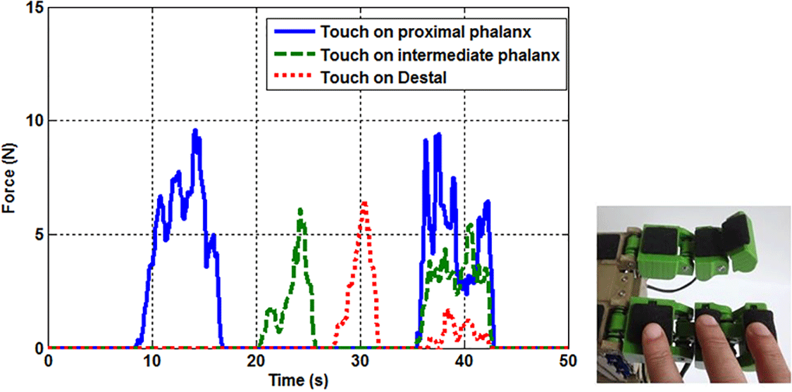
Tests are done by actuating the finger and pressing on phalanges. Actuating servo motor type SH-0253 from 0 to 70∘ resulted in moving the CPRF from its initial to a final position during closing motion without a grasped object as shown in Fig. 11. A second test is done to monitor the calibrated force signals in Newton unit during contact when the applied force is varied. The source of the applied force is the human fingertip as shown in Fig. 12. The contact on phalanges can be sensed simultaneously at the same time with a zero value when there is no touch i.e. without noise (see hyperlink of “Movie 1 CPRF” in the Appendix).
4.1 MIMO Fuzzy Controller
In the practical application of CPRF, the factors that affect the grasping are complex and involve tendon mechanism, multi-VSAs, interactional contact between the phalanges and the grasped object, response time of sensors and servo motors, and CPRF dynamics. Since the majority of these factors are variant with time and nonlinear, calculating the exact mathematical model of the CPRF is not easy. As a result, traditional control methods such as PID method lack providing accurate grasp control. However, the fuzzy control technique can be applied to real applications dependent on knowing an intuitive realization of the best way to control the system (Passino and Yurkovich, 1997). A special MIMO fuzzy controller is designed and applied to the CPRF control system shown in Fig. 13. The controller is a MIMO that sinks the indication from the force sensors, assesses them, and produces a conclusion according to its predefined rules to formulate output torque values in each VSA.
The action of the controller is qualified by fuzzy rules with the relation
of input data mapping and proposition of output, the linguistic variables
are;
FSR_Force 1 = {low, medium,
high}
FSR_Force 2 = {low, medium,
high}
FSR_Force 3 = {low, medium,
high}
VSA_Torque 1 = {low, medium,
high}
VSA_Torque 2 = {low, medium,
high}
VSA_Torque 3 = {low, medium,
high}
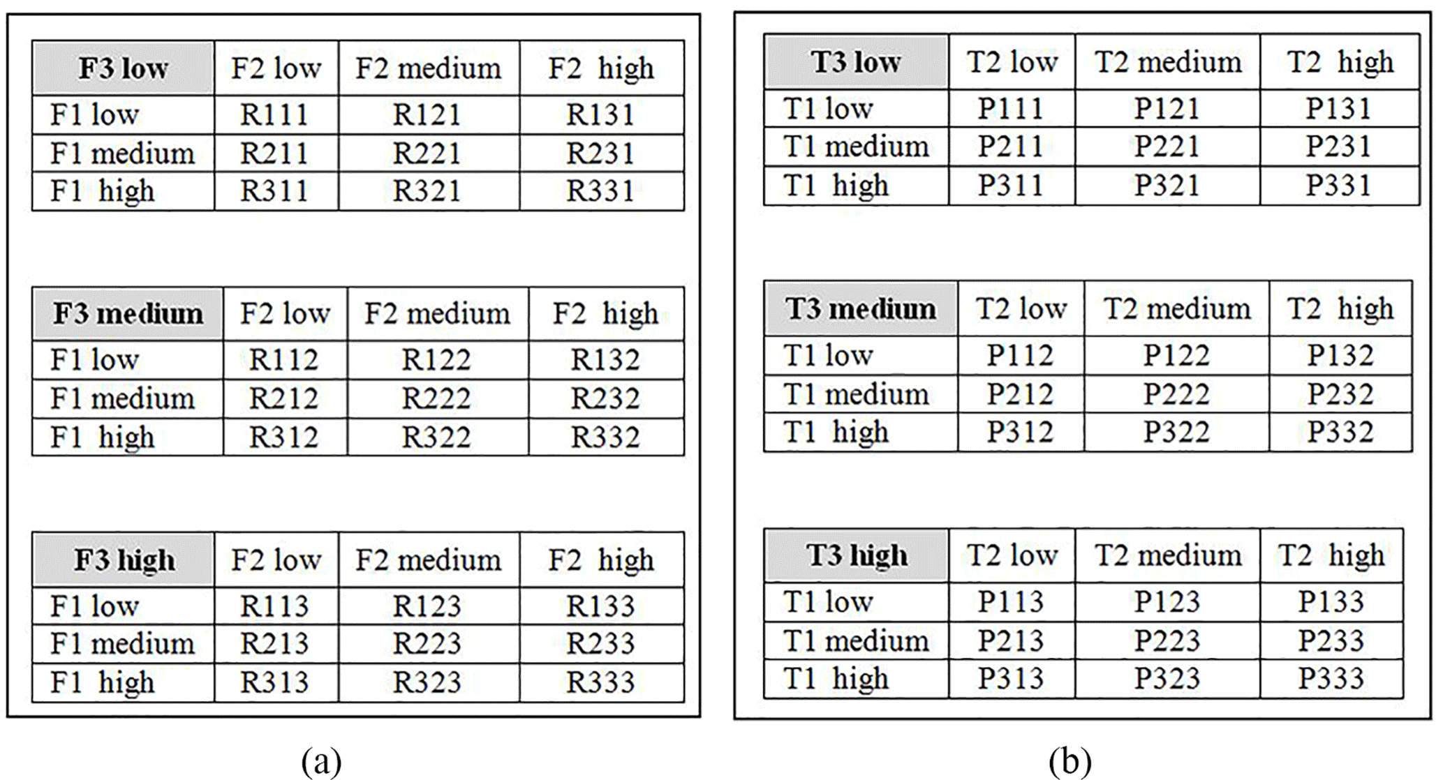
The input variables and output variables have 27 relations Rijk and 27 propositions Pijk, respectively. The relations and propositions are expressed in a matrix form as shown in Fig. 14, where ; Fi = FSR_Force i; Ti = VSA_Torque i. Fuzzy rule are defined now by IF relation then proposition statements as;
The rules, there are 27 rules that determine the values of outputs, are
specified according to the designed relations and proposition matrix shown
in Fig. 14. To clarify the designed rules, let us assume the conditions of
force sensors are;
FSR signal 1 is low, FSR signal 2 is high, FSR signal 3 is low
In this case, as shown in Fig. 14, the rule is set as;
if (FSR Force 1 is low) and (FSR Force 2 is high) and (FSR Force 3 is low)
then (VSA Torque 1 is low) and (VSA Torque 2 is high) and (VSA Torque 3 is
low)
Another example is assumed when the conditions of force sensors are;
FSR Force 1 is high, FSR Force 2 is low, FSR Force 3 is low
Then, as shown in Fig. 14, the rule is set to;
if (FSR Force 1 is high) and (FSR Force 2 is low) and (FSR Force 3 is low)
then (VSA Torque 1 is high) and (VSA Torque 2 is low) and (VSA Torque 3 is
low)
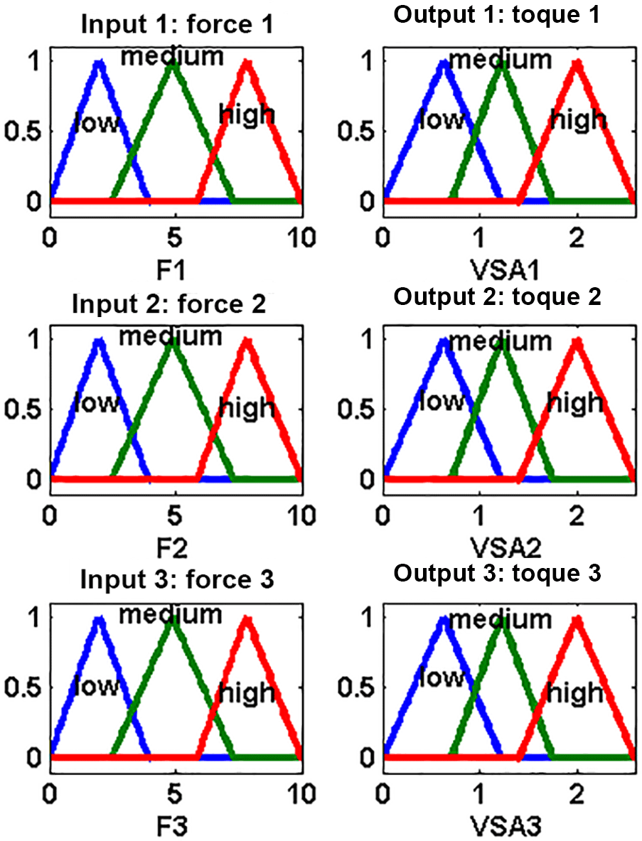
In the same way, the other rules are set according to the state of the input force sensors. The input forces of the controller and the output torques are decomposed into fuzzy sets (low, medium, high) by triangular membership functions of range 〈a b〉 and nucleus 〈c d〉;
Matching to the range of FSR signal of 10-bit data from 0 to 1023, the domain of the input force sensor in Newton unit is set from 0 to 10 N depending on the properties of the applied sensors FSR400 series. The range of the output torque is set depending on the designed VSA. The control strategy is assumed from Δθ equal 0 to 270∘ which results in changes of mean diameter and stiffness from (5.3 mm, 0.2144 N mm degree−1) to (4.627 mm, 0.5512 N mm degree−1) according to Eqs. (8) and (9). Hence, the torque by VSA is supplied in joint space according to Eq. (11) from 0 to 2.5973 N mm.
The plot of the fuzzy sets is presented in Fig. 15, the fuzzy is implemented using Mamdani with the center of gravity defuzzification method of implication minimum operator and aggregation maximum operator. The first step of the fuzzification process is to obtain the crisp of the forces sensors and to determine how these inputs belong to the fuzzy sets. Then, the fuzzified inputs using Eq. (48) is taken and applied to the antecedents of the rules. Since our designed fuzzy controller rule has various antecedents operator, the AND or OR operator is implemented to get the value of the antecedent evaluation. Then, this value is used to the followed membership function. The fuzzy operation (OR) union maximum operator is used to find the disjunction of the rule antecedents, as below;
and the fuzzy operation (AND) intersection minimum operator is used to finding the conjunction of the rule antecedents, as bellow;
4.2 Optimized MIMO Fuzzy Controller
The designed fuzzy controller suffered from undistributed VSA torques in a proper manner. In this situation, there was a large difference between the values of VSA torques which can lead to damage the grasped object. Hence, the boundaries of the input membership functions should be modified to enhance the performance of the controller. Traditional trial and error techniques do not provide optimal solutions. Consequently, a genetic algorithm is applied here to get the optimum boundaries of membership functions so that the difference between the VSA-torques is minimized. A genetic algorithm is an advanced technique for complex issues that realizes optimum value for several systems (Gen and Cheng, 1997). The tuning process of membership boundaries via genetic algorithm is performed using MATLAB. The code takes the calculated data from the designed tradition fuzzy controller Simulink model to compute the difference between the VSA torques. The planning for the implemented genetic algorithm is as follows;
-
Population: the generated population includes the individuals which represented in our case the boundary of the input membership function as;
where and are the index of boundary and contact force, respectively. In the designed fuzzy controller, as shown in Fig. 15, there are three membership functions (low, medium, high) and three contact forces (Force 1, Force 2, Force 3). So, .
-
Fitness function: to optimize the performance of the fuzzy controller, it is important to specify the fitness function. The aim of our fuzzy controller is to supply appropriate close values of VSA-torque during grasping. Consequently, the fitness function is defined as
The adjusting process of boundaries is limited by the physical properties of our force sensors and VSAs. Thus, the limits of the applied genetic algorithm are set as follows;
-
Genetic algorithm parameters: The genetic algorithm is set with the following values; size of population: 90 and number of generation: 40.
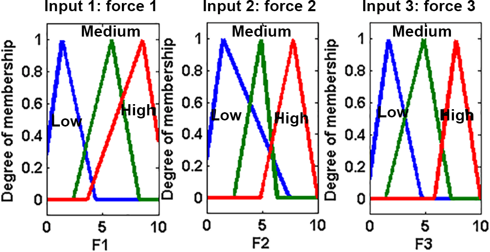
The result of the optimization process of the fuzzy controller in term of the new triangular membership parameters is shown in Fig. 16.
To explain the advancement of the optimized fuzzy controller, the traditional fuzzy controller explained in Sect. 4.1 and optimized fuzzy controller are tested under the contact force touching scenario. The simulation time is set to 15 s. Note that the performance of the controllers is examined under contact forces shown in Fig. 17. Results are shown in Fig. 18 with the VSA-torque compared between Fuzzy and optimized fizzy controllers.


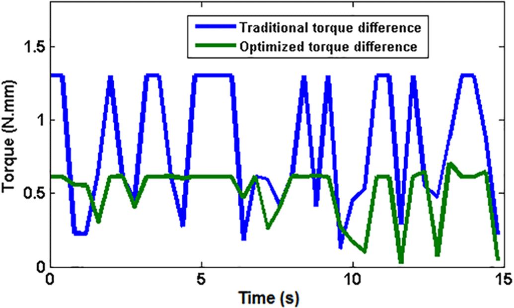
To further explain the distinction between the two controllers, the absolute difference between the VSA torques in each controller of data presented in Fig. 18 is plotted together in Fig. 19. It can be noticed that there is a distinctive difference between the obtained VSA-torques of the two fuzzy controllers. The optimized fuzzy controller has preferred the values of VSA-torques. In turn, the CPRF grasping is enhanced with an appropriate controller in addition to the functionality of the proposed adjustable stiffness tendon-driven mechanism.
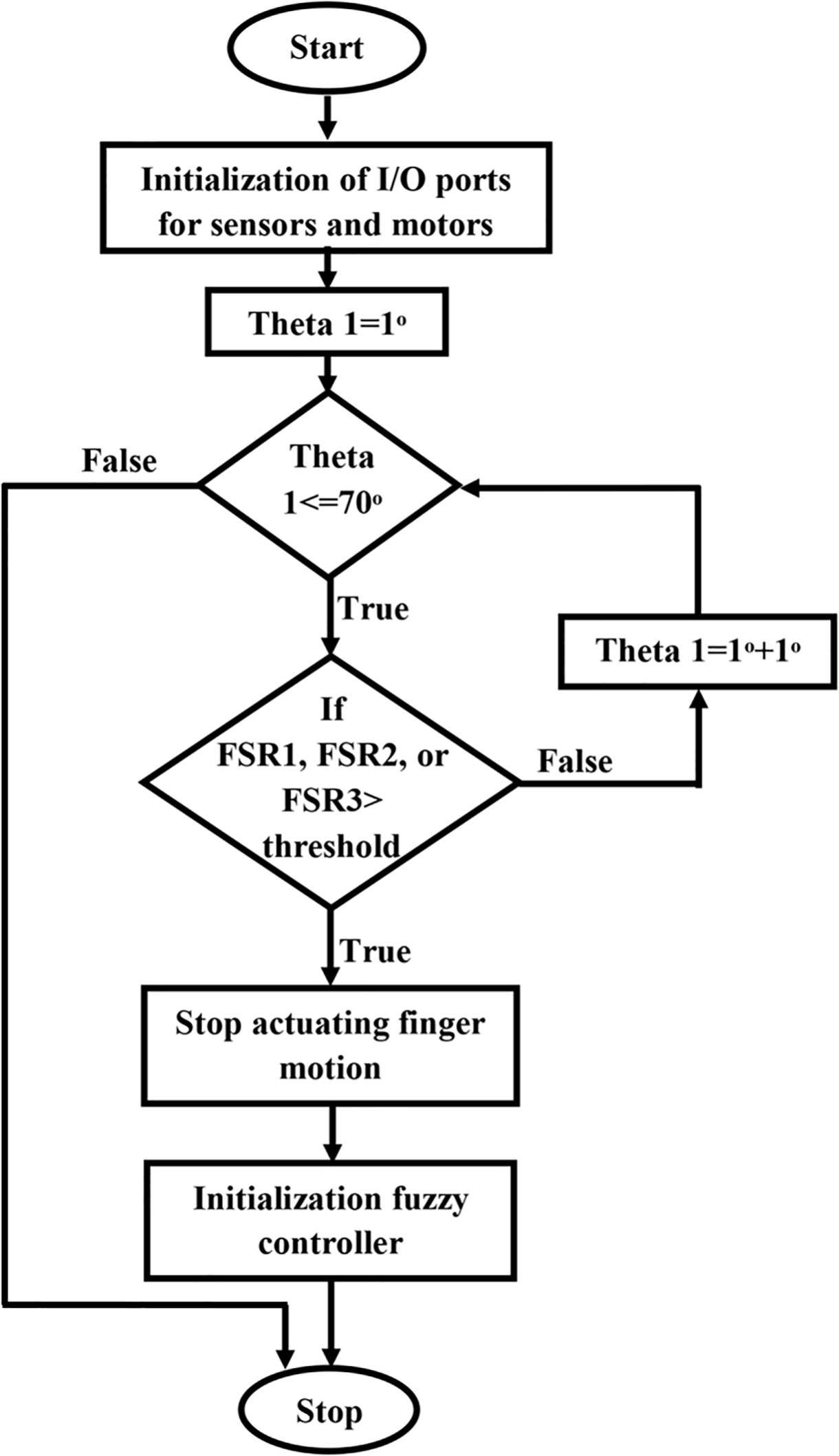
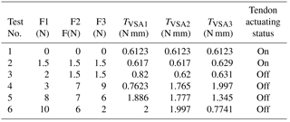
4.3 Operation Control
A simple control algorithm is defined to organize the finger system into many orders and sets. The algorithm is allowed to sense the environment, actuate the finger, and adjust the VSAs according to sensations as shown in Fig. 20. The FSRs analog signals i.e. force sensing in Newton unit are used principally for actuating the finger, adjusting the VSA-torque, and starting the optimized fuzzy controller. Hence, the action of the finger is divided into motion and grasp force spectrum. Motion happens when the system does not sense a grasped object. In the moment of detecting the grasped object, the optimized fuzzy controller is activated to start the grasping phase. Testing with a threshold force equal to 2 N is presented in Table 4. This table explains the response of the VSAs to different touch values over the control algorithm. It can be distinctly seen that the amount of VSA torque varies considerably when there is a touch variation value on the phalanx which is directly in connection with that VSA. For example, according to test 2 and test 3, the finger stopped its motion when the force F1 reached the threshold value. In the same time, the torque of VSA1 increased due to increasing the force on proximal phalanx which is directly connected to it.
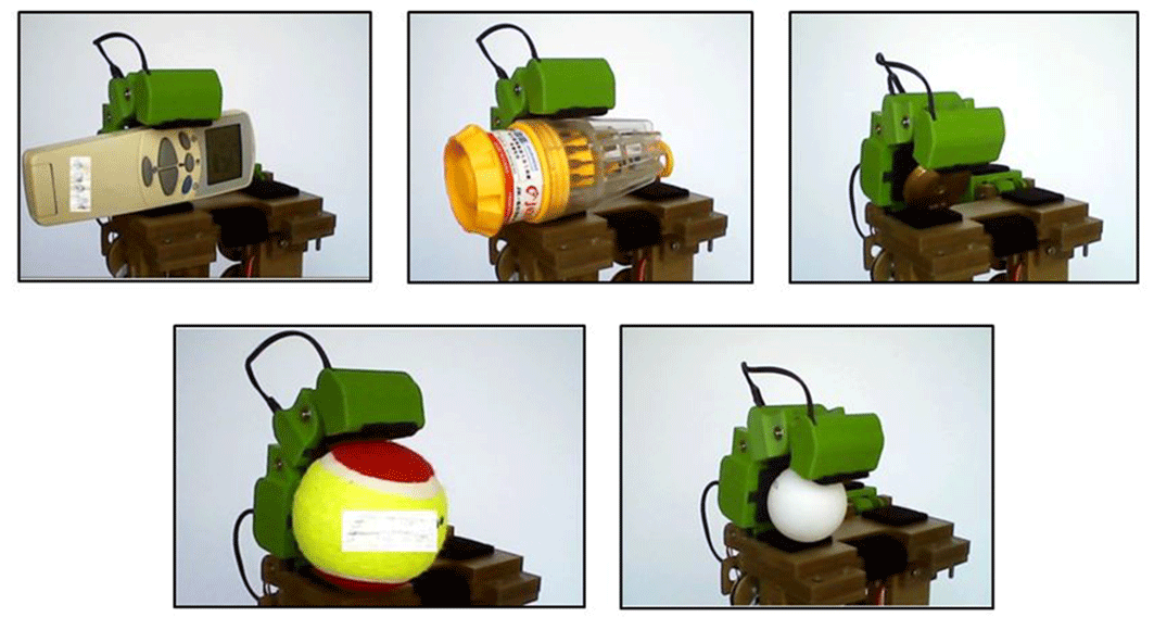
The performance of the developed CPRF prototype is examined in this section. In specific, the grasping ability is tested with different objects as shown in Fig. 21. Taking into consideration that CPRF grasping is characterized by its functionality to grasp different objects of various surfaces shape and type (soft or hard), sizes, and weights.

The advantage of the suggested mechanism with the control algorithm is studied next. The soft tennis ball of Fig. 21 is used in this test, and a threshold value for FSR 1, FSR 2, and FSR 3 equal to 0.0509 N is set. The reaction of the tendon-driven mechanism and the VSA are shown in Fig. 22. As can be seen, the motion of the finger and the operation of the VSAs are interacted together during the planning and holding phases. CPRF was still moving in free motion when the grasping forces were zero. In the moment of sensing the ball, the CPRF stopped its motion and initialized the adjusting VSAs torques according to the fuzzy controller rules. VSA torque increased in cases where there was more load exerted on the phalanx. This is a very important property to support an extra torque in order to prevent the phalanx from moving in the opposite direction, which leads to losing the object. Moreover, the practice results showed that the finger can hold an object firmly even though the hand gripper was moved, the weight of the object was relatively heavy, or an external effect tried to remove the grasped object from the hand (see hyperlink of “Movie 2 CPRF” in the Appendix).
These results indicate beneficial techniques for sensing the grasped objects utilizing only low-cost FSR sensors. The suggested mechanism of VSAs let the ability to improve and adjust low grasped forces of the tendon-driven mechanism. In addition, adjusting the stiffness of VSAs via tendons by motors in the fixed part under the palm rather than the joints of finger reduces the size of fingers. The practice mechanism of CPRF shows that we cannot depend on the motors of the VSAs to actuate the closing sequence of the fingers. If we actuate the closing sequence by VSAs instead of using the underactuated tendon-driven mechanism, because of the tension springs position shown in Fig. 1, the problem that the stiffness of VSA will change randomly in the closing motion without the action of the introduced control algorithm. Thus, the action of the mechanism will not work properly and will not achieve the requirement of adjusting the stiffness in grasping phase to support adjustable grasp forces. From the experimental results shown in Fig. 22, the ball is sensed by distal phalanx at time 5.2 s. in this moment of exceeding the threshold value, the CPRF stopped its motion and initialized the adjusting of VSA torque through the optimized fuzzy controller. Due to the effect of these VSAs torques, the ball is started contacting proximal phalanx at 5.4 s. After time 5.7 s, the ball is pinched by all phalanges. Meanwhile, the VSAs torques are updated their values according to the sensed forces to support the firm grasping. The VSAs torques were close to each other thanks to the optimized fuzzy controller.
VSAs are of distinguished significance for their rules in improving the problem of low grasped forces of the tendon-driven mechanism in fingers. A firm grasping with muscle type joints is established in this paper by incorporating the tendon-driven mechanism with VSAs in the suggested mechanism. The force isotropy property is obtained by introducing a mathematical procedure to obtain the nonlinear cam/pulleys transmission. The suggested sensorimotor system has provided the advantage that grasping can be reached with low-cost force sensing and actuating components. A fuzzy logic controller has been suggested to control the VSAs torques according to the contact force values. For the optimized fuzzy logic controller, GA enabled the VSAs. This to support appropriate torque values in joint space. In addition, the suggested control algorithm has organized the operation of the finger during the planning and holding tasks to grasp objects firmly and in a safe manner. algorithm has regulated the movement of the finger in the planning stage and activated the fuzzy controller to support appropriate VSA torque in the holding stage. The experimental results have proved the ability of the tendon-driven cam/pulleys mechanism to grasp objects successfully in a firm manner without needing a description of any information from the grasped object. In addition, the experimental results have proved the function of the VSAs to hold relative heavy objects and overcome interferences by increasing the grasp forces. This finger prototype is proposed as an initial step, as a future work, it is recommended to improve hand size and the number of fingers as a second step such that it can be closer to a real human hand.
Data can be made available upon reasonable request. Please contact Izzat Al-Darraji (engizzatt@gmail.com).
Video records of this article can be reached online according to the mentioned hyperlinks in Table 5.
IAD, AK, and SK designed the mechatronic system of the robot finger. IAD developed the control algorithms and code. IAD, AK, and SK carried the experiments out. IAD prepared the manuscript with advices from AK and SK. AK and SK revised the manuscript.
The authors declare that they have no conflict of
interest.
Edited by: Lionel Birglen
Reviewed by: four anonymous referees
Albu-Schäffer, A., Wolf, S., Eiberger, O., Haddadin, S., Petit, F., and Chalon, M.: Dynamic modelling and control of variable stiffness actuators, in: Proceedings 2010 IEEE International Conference on Robotics and Automation, 3–7 May 2010, Anchorage, AK, USA, 2155–2162, https://doi.org/10.1109/ROBOT.2010.5509850, 2010.
Ask, T.: Engineering for Industrial Designers and Inventors: Fundamentals for Designers of Wonderful, O'Reilly Media, Sebastopol, CA, USA, 2016.
Aukes, D., Heyneman, B., Duchaine, V., and Cutkosky, M. R.: Varying spring preloads to select grasp strategies in an adaptive hand, in: Proceedings 2011 IEEE/RSJ International Conference on Intelligent Robots and Systems, 25–30 September 2011, San Francisco, CA, USA, 1373–1379, https://doi.org/10.1109/IROS.2011.6095078, 2011.
Birglen, L. and Gosselin, C. M.: Fuzzy Enhanced Control of an Underactuated Finger Using Tactile and Position Sensors, in: Proceedings of the 2005 IEEE International Conference on Robotics and Automation, 18–22 April 2005, Barcelona, Spain, 2320–2325, https://doi.org/10.1109/ROBOT.2005.1570459, 2005.
Birglen, L., Laliberté T., and Gosselin, M.: Underactuated Robotic Hands, Springer, Berlin, Heidelberg, Germany, 2008.
Boucher, J. and Birglen, L.: Performance Augmentation of Underactuated Fingers' Grasps Using Multiple Drive Actuation, ASME. J. Mechanisms Robotics, 9, 041003–041003-10, https://doi.org/10.1115/1.4036220, 2017.
Braun, D., Howard, M., and Vijayakumar, S.: Optimal variable stiffness control: formulation and application to explosive movement tasks, Auton. Robot., 33, 237–253, 2012.
Bundhoo, V., Haslam, E., Birch, B., and Park, E. J.: A shape memory alloy-based tendon-driven actuation system for biomimetic artificial fingers, part I: Design and evaluation, Robotica, 27, 131–146, https://doi.org/10.1017/S026357470800458X, 2009.
Buss, M., Hashimoto, H., and Moore, J. B.: Dextrous Hand Grasping Force Optimization, IEEE Transactions on Robotics and Automation, 12, 406–418, 1996.
Ciocarlie, M., Hicks, F. M., and Stanford, S.: Kinetic and dimensional optimization for a tendon-driven gripper, in: Proceeding 2013 IEEE International Conference on Robotics and Automation, 6–10 May 2013, Karlsruhe, Germany, 2751–2758, https://doi.org/10.1109/ICRA.2013.6630956, 2013.
Dandash, G., Rizk, R., Krut, S., and Dombre, E.: A pseudo-isotropic three phalanxes under-actuated finger, IFToMM'2011: 13th World Congress in Mechanism and Machine Science, June 2011, Guanajuato, Mexico, 1–8, 2011.
Fumagalli, M., Barrett, E., Stramigioli, S., and Carloni,R.: Analysis of an underactuated robotic finger with variable pinch and closure grasp stiffness, 2016 IEEE International Conference on Advanced Intelligent Mechatronics (AIM), 12–15 July 2016, Banff, AB, Canada, 365–370, https://doi.org/10.1109/AIM.2016.7576794, 2016.
Gen, M. and Cheng, R.: Genetic Algorithms and Engineering Design, Wiley, New York, USA, 1997.
Hristu, J., Babb, J., Singh, H., and Gottschlich, S.: Position and force control of a multifingered hand: a comparison of fuzzy logic to traditional PID control, in: Proceeding of the IEEE/RSJ/GI International Conference on Intelligent Robots and Systems, 12–16 September 1994, Munich, Germany, 2, 1391–1398, https://doi.org/10.1109/IROS.1994.407502, 1994.
In, H. and Cho, K. J.: Concept of variable transmission for tendon driven mechanism, in: Proceeding 2013 10th International Conference on Ubiquitous Robots and Ambient Intelligence (URAI), 30 October–2 November 2013, Jeju, South Korea, 15–16, https://doi.org/10.1109/URAI.2013.6677459, 2013.
Kino, H., Okamura, N., and Yabe, S.: Basic characteristics of tendon-driven manipulator using belt pulleys, In: Proceeding 2004 IEEE/RSJ International Conference on Intelligent Robots and Systems (IROS) (IEEE Cat. No.04CH37566), 28 September–2 October 2004, Sendai, Japan, 2, 1287–1292, https://doi.org/10.1109/IROS.2004.1389573, 2004.
Krut, S.: A Force-Isotropic Underactuated Finger, in: Proceeding of the 2005 IEEE International Conference on Robotics and Automation, 18–22 April 2005, Barcelona, Spain, 2314–2319, https://doi.org/10.1109/ROBOT.2005.1570458, 2005.
Kuo, P. H., DeBacker, J., and Deshpande, A. D.: Design of robotic fingers with human-like passive parallel compliance, in: Proceeding 2015 IEEE International Conference on Robotics and Automation (ICRA), 26–30 May 2015, Seattle, WA, USA, 2562–2567, https://doi.org/10.1109/ICRA.2015.7139543, 2015.
Ozawa, R., Hashirii, K., and Kobayashi, H.: Design and control of underactuated tendon-driven mechanisms, in: Proceeding of 2009 IEEE International Conference on Robotics and Automation, 12–17 May 2009, Kobe, Japan, 1522–1527, https://doi.org/10.1109/ROBOT.2009.5152222, 2009.
Ozawa, R., Kobayashi, H., and Hashirii, K.: Analysis, Classification, and Design of Tendon-Driven Mechanisms, IEEE Transactions on Robotics, 30, 396–410, https://doi.org/10.1109/TRO.2013.2287976, 2014.
Palli, G. and Melchiorri, C.: Interaction Force Control of Robots with Variable Stiffness Actuation, 18th IFAC World Congress, 44, 13504–13509, 2011.
Passino, K. M. and Yurkovich, S.: Fuzzy Control, Addison-Wesley Longman Publishing Co., Redwood City, CA, USA, 1997.
Pololu Force Sensing Resistor: Pololu robotics and electronics, available at: https://www.pololu.com, last access: 25 February 2018.
Pratt, G. A. and Williamson, M. M.: Series elastic actuators, in: Proceedings 1995 IEEE/RSJ International Conference on Intelligent Robots and Systems, Human Robot Interaction and Cooperative Robots, 5–9 August 1995, Pittsburgh, PA, USA , 1, 399–406, 1995.
Rizk, R., Krut, S., and Dombre, E.: Grasp-stability analysis of a two-phalanx isotropic underactuated finger, in: Proceeding 2007 IEEE/RSJ International Conference on Intelligent Robots and Systems, 29 October–2 November 2007, San Diego, CA, USA, 3289–3294, https://doi.org/10.1109/IROS.2007.4399169, 2007.
Rodríguez, N.: Optimal design of driving mechanism in a 1-DOF anthropomorphic finger, Mech. Mach. Theory, 41, 897–911, https://doi.org/10.1016/j.mechmachtheory.2006.03.016, 2006.
Shigley, J. and Mischke, C.: Standard handbook of machine design, McGraw-Hill STANDARD HANDBOOKS, Ney York, USA, 2004.
Wolf, S., Grioli, G., Eiberger, O., Friedl, W., Grebenstein, M., Höppner, H., Burdet, E., Caldwell, D. G., Carloni, R., Catalano, M. G., Lefeber, D., Stramigioli, S., Tsagarakis, N., Damme, M. V., Ham, R. V.,Vanderborght, B., Visser, L. C., Bicchi, A., and Albu-Schäffer, A.: Variable Stiffness Actuators: Review on Design and Components, IEEE/ASME Transactions on Mechatronics, 21, 2418–2430, 2016.