the Creative Commons Attribution 4.0 License.
the Creative Commons Attribution 4.0 License.
 | 04 Jan 2018
Continuous Static Gait with Twisting Trunk of a Metamorphic Quadruped Robot
Chunsong Zhang
Jian S. Dai
The natural quadrupeds, such as geckos and lizards, often twist their trunks when moving. Conventional quadruped robots cannot perform the same motion due to equipping with a trunk which is a rigid body or at most consists of two blocks connected by passive joints. This paper proposes a metamorphic quadruped robot with a reconfigurable trunk which can implement active trunk motions, called MetaRobot I. The robot can imitate the natural quadrupeds to execute motion of trunk twisting. Benefiting from the twisting trunk, the stride length of this quadruped is increased comparing to that of conventional quadruped robots.
In this paper a continuous static gait benefited from the twisting trunk performing the increased stride length is introduced. After that, the increased stride length relative to the trunk twisting will be analysed mathematically. Other points impacting the implementation of the increased stride length in the gait are investigated such as the upper limit of the stride length and the kinematic margin. The increased stride length in the gait will lead the increase of locomotion speed comparing with conventional quadruped robots, giving the extent that natural quadrupeds twisting their trunks when moving. The simulation and an experiment on the prototype are then carried out to illustrate the benefits on the stride length and locomotion speed brought by the twisting trunk to the quadruped robot.
- Article
(2978 KB) - Full-text XML
-
Supplement
(21156 KB) - BibTeX
- EndNote


The development of quadruped robot is one of the most attractive research fields in the robotics community, since they perform superior advantages over wheeled robots on rough terrains (de Santos et al., 2007). Works have been carried out in the field in recent years, such as LittleDog (Kolter and Ng, 2011), BigDog (Raibert et al., 2008), HyQ (Boaventura et al., 2013), Tekken (Fukuoka et al., 2003), Cheetah-cub (Spröwitz et al., 2013), LS3 (Bloss, 2012) [7], Baby Elephant (Chen et al., 2014), MIT Cheetah (Hyun et al., 2014) and so on. Conventionally, trunks of quadruped robots are all designed as a single rigid body or with a passive compliant joint. The trunk in these robots play a role as carriers for legs, electric boards, power sources, manipulators and so on. As far as the current search being carried out, there are no trunks that can make contributions to motion of the quadruped robots actively. This becomes one of the largest differences between man-made and natural quadrupeds, since the natural quadrupeds often twist their trunks to walk, run or climb, such as geckos and lizards. To overcome this, this paper for the first time proposes a trunk-moveable metamorphic quadruped robot (Zhen et al., 2016), called the MetaRobot I, which can change the shape of its trunk and imitate the natural quadruped to twist its trunk.
The twisting trunk will affect many characteristics of quadruped robots. First of all, this paper choose to explore its effect on the stride length of quadruped robots. The stride length is a fundamental characteristic of the gait of quadrupeds. Alexander (1984) defined it as the distance the robot travelled during a complete circle of leg movements. In de Santos et al. (2007) it is defined as the distance travelled by the COG (center of gravity) of the body along a gait cycle. Obviously it plays a crucial role in the features of locomotion. Koechling and Marc (1993) regarded it as one of the two essential characteristics that determine the locomotion speed of the quadruped together with the gait cycle. Leeser (1996) and Pouya et al. (2016) tried to increase the stride length aiming to increase the locomotion speed by flexing the spine in the vertical plane. Nevertheless, they did not investigate the mathematical relation between the stride length and the flexion angle. Baisch et al. (2014) measured the stride length to reveal the speed of the quadruped robot. Hodgins and Raibert (1991) studied the method to control the step length to adjust to suitable footholds to keep balance in rough terrain. Krishna and Kumar (2016) investigated the influence of stride length on the energy cost in constant height level bounding gait of quadruped robots and found that lower stride lengths give lower mechanical cost of transport. Chen et al. (2017) looked into the impact of stride length on energy consumption of trotting gait for a quadruped robot and found that for a given speed the energy cost gets lower as the stride length becomes larger. Chan and Liu (2016) generated a turning gait by regulating step lengths of each leg. Hence the stride length (or step length) can be used to increase speed, reduce energy consumption, keep balance and generate gaits for quadruped robots.
On most occasions people hope the quadruped robots to get a larger stride length to perform better efficiency, especially referring to the locomotion speed. As we can see, referring to Fig. 1, the lizards perform continuous static gait with twisting trunk. In general, natural quadrupeds often twist their trunks, when they walk. From this one can easily image that the twisting trunk can increase the stride length and further to improve the speed. There were several researches studied the gait design with twisting trunk. Park et al. proposed methods on the discontinuous spinning (Park et al., 2005) and zigzag (Park and Lee, 2007) gaits design for a quadruped robot with a waist-joint. The waist-joint here was a passive joint and it was driven by the four legs' movement. Wu et al. (2014) analysed a dynamic gait for a gecko inspired climbing robot with a pendular waist. Nevertheless, the joints implementing twisting motion on the trunk were all passive joints in formal researches and few study on the impacts of trunk twisting on the stride length has been done in the robotics community so far. Since conventional quadruped robots never get any moveable trunks that can implement active trunk motion let alone mentioning impacting the stride length.

However, this changes with the MetaRobot I that has the moveable metamorphic trunk. This paper hence proposes a continuous static gait with the twisting trunk imitating the natural quadrupeds. Through this gait the increased stride length due to the twisting trunk will be investigated. The increased stride length in the gait will improve the locomotion speed comparing with conventional quadruped robots, which is one of the benefits that the twisting trunk brings to the quadruped robot. This explains why the natural quadrupeds twist their trunks when moving.
The stride length has a close relation with the twisting angle of the trunk and the twisting trunk has an impact on the stride length fundamentally. The paper explores the essential relation between the stride length and the trunk twisting angle and reveals how the stride length is increased by the twisting trunk. The other factors impacting the implementation of the increased stride length in the continuous static gait will be investigated.
The paper is organized as follows. The structure of MetaRobot I will be illustrated in Sect. 2. The continuous static gait benefited from the twisting trunk will be introduced in Sect. 3. Further in Sect. 3 three key points to accomplish the increased stride length in the gait are proposed as the increased stride length, the upper limit of the stride length and the kinematic margin. The increased stride length relative to the trunk twisting will be investigated in Sect. 4. The upper limit of the stride length in the continuous static gait and the corresponding twisting angles are to be investigated in Sect. 5. The suitable twisting angle to keep kinematic margins more than zero in continuous static gaits is explored in Sect. 6. A simulation and a physical experiment on the prototype to test the gait are implemented in Sect. 7.
The robot has a planar 6-bar linkage as its trunk, showed in Fig. 2. Lengths of links in the trunk are defined as AF = BC = DC = EF = and AB = DE = 2l3. Hip joints are labeled with Pi and the leg mounted at Pi is named as leg i (i=1, 2, 3, 4). The offset distance is set as e from the center of each hip to the link on which the hip is mounted. The lengths of leg links are d1, d2, d3 respectively. The robot will not vary the height of the trunk relative to the ground. In the prototype, the parameters are set as Table 1 shows.
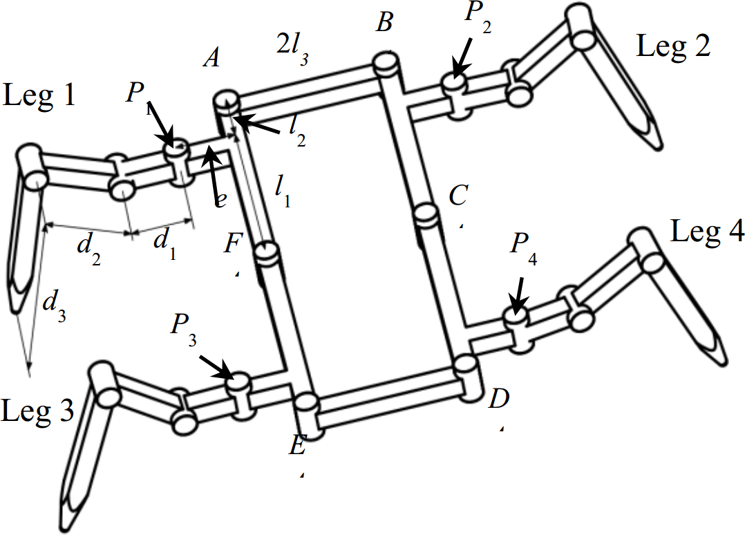
Table 1Geometric parameters of the metamorphic quadruped robot with the units of mm.

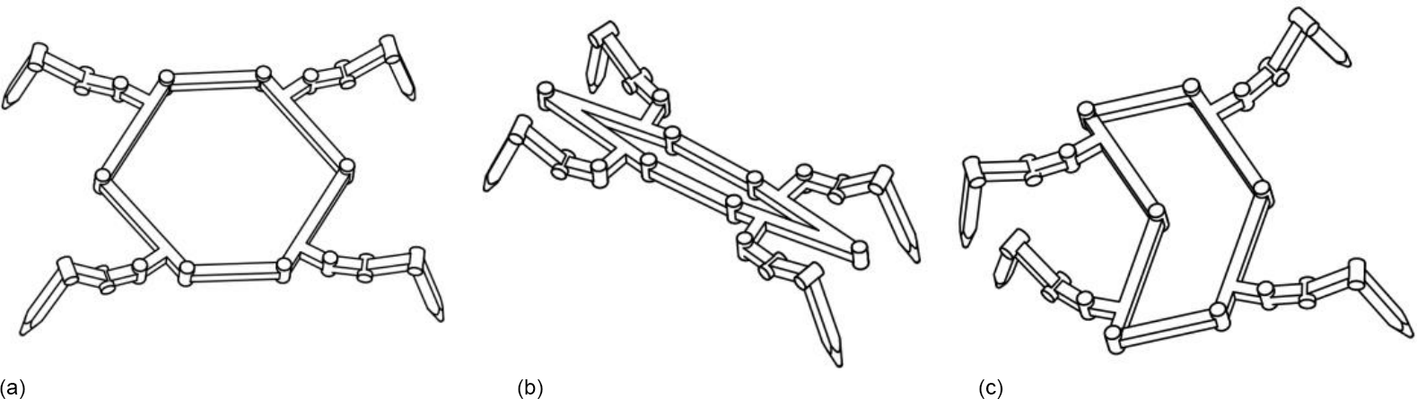
As the 6-bar linkage has 3 DOFs, to fully control the trunk, joints A, E and C are appointed to be the active joints. Under this configuration, the trunk can change its form. This characteristic gives the robot multiple body shapes. Hence the robot is called the metamorphic quadruped robot, MetaRobot for short. Some of the body shapes are close to those of natural quadrupeds endowing the robot the ability of imitating different animals such as crabs in Fig. 3a, phasmids in Fig. 3b and geckos in Fig. 3c. This specific ability can be called multi-bionics. As far as the author know, this is a special ability that few bio-inspired robots acquire.
The robot performs particular abilities in different body shapes. It will get larger stability when stand somewhere to work as a crab, pass through narrow alley easier by simulating a phasmid and twist its trunk to move faster when imitating a gecko.
It is worth mentioning that the trunk twisting is the action most similar to that of a natural animal does, as the most animals twist their trunks when they move. The motion of trunk twisting must bring much more benefits to the capacity of quadrupeds. Nevertheless, few efforts were done to investigate its impacts on performances of quadrupeds around the robotic community till now. As mentioned above this paper will for the first time concentrate on the influence of the twisting trunk on stride length in the continuous static gait.
Referring to Fig. 5, assuming that interior angles of joints A, E and C are ∠A, ∠E and ∠C respectively. Then it is easy to know that to perform the twisting motion, the relationship between the three joints should be restricted as . For simplification, we define the trunk twisting angle θ as the angle that links CD and EF deviating from their original orientation. It is measured by rotating the links from their original places to the final places, and if the rotating direction is anticlockwise the twisting angle will be positive, otherwise it will be negative.
A continuous static gait is designed with the twisting trunk of the MetaRobot I to imitate the walking gait of natural quadrupeds like lizards. The gait is designed under the assumptions below.
-
The robot walks on the flat terrain;
-
The robot walks in a straight line;
-
The robot walks with a constant speed;
-
The trunk will remain horizontal and keep the distance h constant between the COG (Centre Of the Gravity, is the mass centre of the trunk ignoring mass of the four legs) and the ground, and h=d3;
-
Each of the leg takes the step length by sstep, the trunk moves the length by , during one period of step.
Showed in Fig. 4, the gait will be implemented in procedures as below.
-
Step (1): It is in its original phase with body remaining rectangle, the legs 1 and 3 are in the middle of their workspace, and the legs 2 and 4 are in the rear boundary of their reachable areas;
-
Step (2): The body twists by the angle of θ and moves forward by the length of , and leg 4 moves forward by length of ;
-
Step (3): The body twists back to the original shape and moves forward by the length of , leg 2 moves forward by the length of ;
-
Step (4): The body keeps in rectangle and moves forward by the length of , by now the MetaRobot I has already accomplished half the gait cycle, the body is in its original shape as a rectangle, leg 1 and 3 are in the rear boundary of their workspace, leg 2 and 4 are in the middle of their reachable areas;
-
Step (5): The body twists by the angle of −θ and moves forward by the length of , and leg 3 moves forward by length of ;
-
Step (6): The body twists back to the original shape and moves forward by the length of , and leg 1 moves forward by the length of ;
-
Step (7): The body keeps in rectangle and moves forward by the length of , by now the MetaRobot I has accomplished all the gait cycle, the body is in its original shape as a rectangle, leg 2 and 4 are in the rear boundary of their workspace, leg 1 and 3 are in the middle of their reachable areas and it is ready to execute following gait cycles.
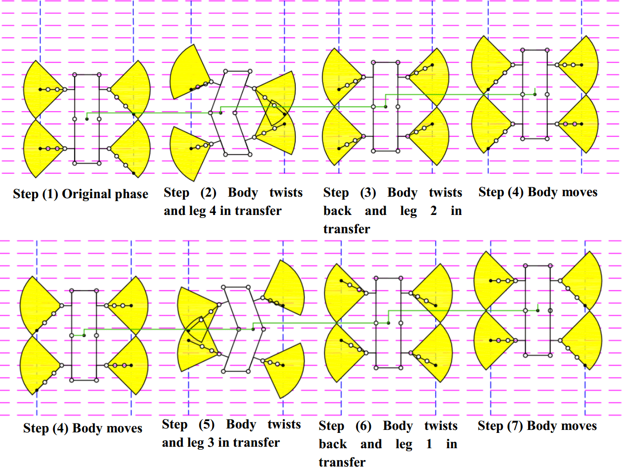
Figure 4The motion sequence of the MetaRobot I executing the continuous periodic gait in one period. The black point in center of the trunk represents the COG of the robot. The green lines are used to describe the displacement of the robot after each step. The quadrant in yellow indicates reachable areas of footholds of legs.
Obviously, after step (7) the robot will recover to the state of step (1). After one gait cycle, the trunk moves the stride length as . Each of the legs moves by the length of . In order to recover to the original posture after one gait cycle, it must have
It is easy to see the robot will remain stable during the whole gait cycle. Hence the gait will be implemented successfully by careful design. To accomplish the gait, it needs to consider other three points as
-
The increased stride length. As mentioned above the twisting trunk can increase the stride length of quadruped robot. From Eq. (1), it is convenient to find that the stride length can be increased by increasing the step lengths of legs. The paper will later investigate how the twisting trunk increases the step length so as the robot gets larger stride length and locomotion speed. And also the paper will find the monotonicity of the step length relative to the twisting angle.
-
The upper limit of the stride length in the continuous static gait. From the Fig. 4, after step (4) the legs 1 and 3 are both in the rear boundary of their reachable area. Hence the stride length is also limited by the reachable area except the twisting angle. Hence it is necessary to find the upper limit of the stride length and the corresponding twisting angles in the continuous static gait for the MetaRobot I. So that it can acquire the maximum speed. From the analysis below it can be revealed that the MetaRobot I will get higher upper limit of the stride length than conventional with rigid trunks in the continuous static gait due to the twisting trunk.
-
Kinematic margins (McGhee and Iswandhi, 1979) of all legs should be more than zero during the gait cycle. Referring to Fig. 4, after step (2) the leg1 is close to the rear boundary of its reachable area, which is easy to go outside. Hence if the MetaRobot I wants to perform the increased stride length, it must choose the suitable twisting angle that guarantees all the footholds inside their reachable areas.
After these three points are solved the continuous static gait with twisting trunk can be implemented. The paper will investigate these three points later respectively.

Figure 5Reachable areas on the ground of leg 4. The quadrant in solid line is the reachable area before trunk twisting, the quadrant in black dash line is that after trunk twisting.
The stride length has close relation with the step length. According to Eq. (1) in this paper the stride length is represented by calculating the step length of legs. Referring to Fig. 5, it is convenient to figure out that the motion of trunk twisting will lead the reachable area of the foothold on the ground to move and this may further result in enlarging the size of one single step length of a leg. This progress is like the actions some animals execute such as geckoes, crocodiles or lizards, as they all twist trunks when moving. For a conventional quadruped robot, it cannot implement this progress. And this difference between the metamorphic and conventional quadruped robot is the key point that makes the increase of the stride length happen.
Assuming that the MetaRobot I performs straight forward gaits while twisting its trunk. Here the hip joint angle is limited between −45 and 45∘, hence the reachable area of the foothold on the ground is a quadrant, as Fig. 5 shows. Since the legs are mounted symmetrically on the trunk, their step length will present similar expression in the trunk twisting angle.
Hence we take the leg 4 as an instance. In Fig. 5 the solid and dash line sketches the shapes of the trunk and locations of the reachable area of foothold of the leg 4 before and after trunk twisting respectively; P4 and are the center of the hip 4 before and after trunk twisting respectively.
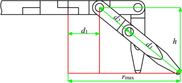
To solve the expression of step length, the radius of reachable area (rmax) of the foothold should be obtained. For a given quadruped robot, the radius is determined by the length of links on its legs. For the MetaRobot I, referring to Fig. 6, the radius can be calculated by equation below.
Where rmax indicates the radius of reachable area of foothold and h=d3 indicates the height of the trunk from the ground.
For the metamorphic quadruped robot acting periodic gaits, the body coordinate system O−xyz is established in a special way. When the trunk is in its original shape before twisting, the origin of O−xyz is at the geometric center of trunk; the x-axis points to the right side of the trunk parallel to the link AB; the y-axis points to the front side of the body perpendicular to the link AB; the z-axis is determined by the right hand rule. When the body twists during one period, referring to Fig. 5, the body coordinate O−xyz will not change its location or orientation, on the other hand when the body moves during one period the body coordinate O−xyz will translate the same displacement with the body without changing its orientation. It is convenient to find that when the robot finishes one gait cycle, the coordinate O−xyz will move its location to the geometric center of body in its original shape before trunk twisting without changing its orientation.
In Fig. 5, we define the lateral distance between the hip 4 and the foothold of the leg 4 along the x-axis as r. It is easy to see that the step length of the leg 4 can be increased only when r<P4H4, since when r≥P4H4 there is no room in the dash line quadrant (after trunk twisting) that is in front of the quadrant in solid line (before trunk twisting), which is the incremental part of the increased step length compared with that of the quadruped without trunk twisting.
Furthermore, the increased step length of the leg 4 will have different expressions in the twisting angle θ when r ranges from 0 to P4N4 and from P4N4 to P4H4 respectively, since when , the front boundary of the quadrant after trunk twisting is a straight line, and when , the front boundary of the quadrant after trunk twisting is a part of arc. Hence to calculate the increased step length of the leg 4, it needs to find expressions of P4N4 and P4H4.
4.1 Hip locations varying with the trunk twisting that impacting the step length
From Fig. 5, it is convenient to see that hip locations directly determine the positions of the reachable area of footholds, which will further influence the step length. In other words, the movement of the hip is the reason why the reachable area of foothold move on the ground. And it will also influence the expressions of P4N4 and P4H4. Hence, before finding the expressions of P4N4 and P4H4, it is necessary to calculate the expression of locations of the hips in respect of the twisting angle θ first.
In the body coordinate system O−xyz, through the method of matrix transformation the hip locations Pi (i=1, 2, 3, 4) is derived as below.
4.2 The longest lateral distance P4H4 allowing increasing the step length with the twisting trunk
The length ofP4H4 in Fig. 5 is the longest lateral distance allowing enlarging the step length. Figure 7 shows the feature of the reachable areas before and after trunk twisting (removing the final black dash line quadrant and using its equivalent in the blue dash line instead), which shows the equivalent transformation progress. The transformation progress can be divided into two sub-progresses as a translation and a rotation around the center of quadrant. And the progress of translation is divided into translation along the x-axis and y-axis respectively. The pink dash line quadrant is the area after translating along the x-axis. The blue dash line quadrant is the area after translating along the y-axis (the final area after the translation). For a circle it will not change the intersection point between it and a line when rotating the circle around its center in the plane where the circle and the line both lie in. Hence the intersection point G4 between the blue dash line quadrant and the black solid quadrant can be used to present the intersection point between the black dash line quadrant and the black solid quadrant in Fig. 5.
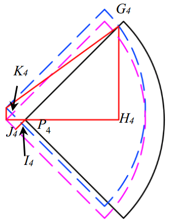
Figure 7Equivalent transformation progress of reachable area of leg 4. First, translating to the quadrant of pink dash line centering on , then to the quadrant of blue dash line centering on . Where I4 is the intersection point of the blue dash line and the short red line; K4 is the intersection point of the blue dash line and the pink dash line.
Defining the displacements of point P4 along x-axis and y-axis during the translation progress as Δx4 and Δy4. According to Eq. (3), Δx4 and Δy4 can be calculated by
From Fig. 7 it is easy to see and . Also some segments can be presented with Δx4 and Δy4 as
In the right triangle , the G4I4 can be calculated by
Then
Hence, the length of P4H4 can be derived as
4.3 The lateral distance P4N4 which is the boundary between the two expressions of increased step length with the twisting trunk
Now it's turn to solve the length of P4N4 which is the boundary between the two expressions of the increased step length. Figure 8 shows the feature of reachable areas of leg 4 before and after trunk twisting. is perpendicular to N4M4 and parallel toP4N4.

Figure 8Two reachable area of leg 4 before (solid line) and after (dash line) trunk twisting.
It is easy to get the relationship below.
is in the right triangle and
Hence, the length of P4N4 can be derived as
4.4 The incremental part of the increased step length when with the twisting trunk
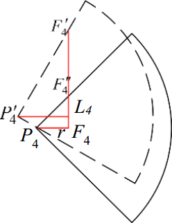
Figure 9Two reachable area on the ground and enhanced stride length () of leg 4 before and after the trunk twisting when . Where F4 is the original foothold, is the farthest foothold after trunk twisting and is the farthest foothold without trunk twisting.
Figure 9 shows increased step length after the trunk twisting when . It is convenient to see the key to solve the increased step length is to get the expression of , since is the incremental part of the increased step length with trunk twisting compared with that without the trunk twisting.
From Fig. 9, relationships below can be derived.
In the right triangle there exists
Hence the incremental part of the increased step length with trunk twisting compared with that without trunk twisting is
Where Δsstep indicates the incremental part of the increased step length.
4.5 The incremental part of the increased step length when with the twisting trunk

Figure 10Two reachable area on the ground and increased stride length of leg 4 before and after trunk twisting when . Where F4 is the original foothold, is the farthest foothold after trunk twisting and is the farthest foothold without trunk twisting.
Figure 10 shows the increased step length after the trunk twisting when . In Fig. 10,
And
In the right triangle , there exists
And
Since L4F4=Δy, then
Hence
Where Δsstep indicates the incremental part of the increased step length.
4.6 The stride length increased by the twisting trunk
According to Eq. (1), the incremental part of stride length is
From Figs. 9 and 10 it is easy to see that the increased step length can be calculated by the equation below.
where sstep indicates the increased step length after trunk twisting. Combining Eqs. (14), (20) and (22), the expression of the increased step length can be derived as
The increased stride length sstride after trunk twisting can be derived by combining Eqs. (1) and (23).
4.7 Monotonicity of the stride length increased by the twisting trunk
Based on Eq. (1), the monotonicity of the stride length is the same as the step length. Hence the monotonicity of the stride length will be represented by investigating the monotonicity of the step length. From Eq. (23), it is easy to find that the increased step length varies with the lateral distance r from foothold F4 to the hip center P4 and the twisting angle θ. The expression of the increased step length in respect of r and θ is complex. Nevertheless, there is still a way to further investigate the monotonicity of the increased step length sstep along with r and θ to figure out the best lateral distance rb for r and the best twisting angle θb for θ that give the largest step length sstep. The idea is that first to pay attentions to the relationship between sstep and r to find the rb with a specific twisting angle θ, then to study the law between sstep and θ to seek the rb that when r=rb.
From Eq. (23), it is convenient to see when , the increased step length sstep will get larger if r or θ increases. In other words, sstep is a monotonic increasing function in respect of r and θ. Hence, in this situation the increased step length gets its largest value when r=P4N4.
When , the partial differential equation of sstep about r is
According to Fig. 10, , and when , ; when , . Hence a useful inference can be obtained as below.
if and , if
The value of depends on r and it is easy to see decreases when r increases. And when r=P4N4, ; when r=P4H4, . Hence when r changes ranging from P4N4 to P4H4 there exists a moment that and the increased step length gets its largest value when . And at that moment, equation below can be established to calculate rb.
Then
This is to say for a specific trunk twisting angle θ, when r=rb, the increased step length sstep gets its largest value.
Now substitute Eq. (26) into Eq. (23) to seek for the best twisting angle θb for θ that give the largest step length, leading the equation below.
Substituting Eq. (4) in Eq. (27) leads to the partial longest increased step length
From the equation above, the differential equation of about θ is
As and obviously , then
if
Which will always be correct. And if , then inferences below can be derived.
if and , if
Hence the conclusion can obtained as when , the partial longest increased step length is a monotonic increasing function in respect of θ, for this situation the best trunk twisting angle θb is the biggest angle the robot can twist; and when , the partial longest increased step length first decreases along with the trunk twisting angle θ, and then increases, for this situation the best trunk twisting angle θb is 0 (no twisting) or the biggest angle the robot can twist.
The stride length shows the same monotonicity as the step length. Commonly for natural quadrupeds, they always make sure that , hence for natural quadrupeds they need to twist as much as possible to make their stride lengths as large as possible if they want to move as quickly as possible.

Figure 11Enhanced stride length varying with the twisting angle θ and the lateral distance r in the continuous periodic gait.
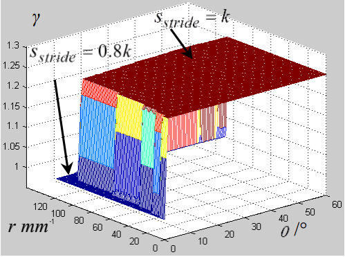
Figure 12Ratio between the enhanced stride length and longest stride length varying with the twisting angle θ and the lateral distance r in the continuous periodic gait.
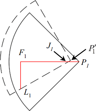
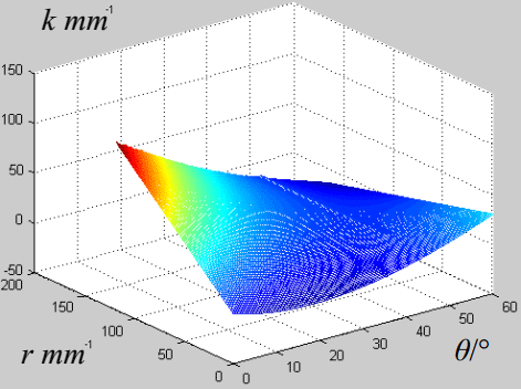
Figure 14Kinematic margin of leg 1 varying with twisting angle θ and lateral distance r between hip 1 and the original foothold.
Defining k as the distance from the rear boundary to the front boundary of the reachable area of a leg along the direction of locomotion. It needs to pay attention to the relationship between the upper limit of the stride length sstride and the distance k. Since after step (4), legs 1 and 3 are in the rear boundary of their reachable areas when the quadruped finished half of the gait cycle if stride length sstride is equal to the distance k. Hence the upper limit of the stride length sstride in the continuous static gait cannot be larger than the distance k, or both the kinematics margin of legs 1 and 3 will be negative.
For a quadruped robot without trunk twisting, after step (4) there is no way for leg 1 to keep its foothold in its reachable area as the body keeps moving forward in step (5) if stride length sstride is equal to the distance k. This will fail the gait. To avoid this situation the quantitative relationship between sstride and k for the quadruped without trunk twisting should be
Which is less than the distance k.
In contrast, things will change for the MetaRobot I which can twist its trunk. In step (5) it twists its trunk to translate the reachable area of leg 1 to keep the foothold in the reachable area, as Fig. 4 shows. To achieve this, the quantitative relation below must be met, that is
For the MetaRobot I whose upper limit of the stride length sstride is going to be equal to the distance k, as sstride=k. Then
Obviously, since the hip joint angle is limited between −45 and 45∘, the distance k has a fixed quantitative relationship with the lateral distance r as
Hence there is a further quantitative relationship between Δsstep and r to guarantee the continuous static gait with trunk twisting performing the upper limit of the stride length equal to the distance k. That is
The solution set of Eq. (34) is the set of all the suitable pairs of the twisting angle θ and the lateral distance r for situation that the upper limit of the stride length is equal to the distance k (sstride=k) in the continuous static gait. It can be solved using numeric method by Matlab referring to the Eqs. (14) and (20). Figures 11 and 13 are drew using the geometric parameters in Table 1 to show this solution set.
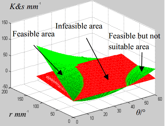
Figure 15Remaining kinematic margin of leg 1 and eighth of stride length varying with twisting angle θ and the lateral distance r.
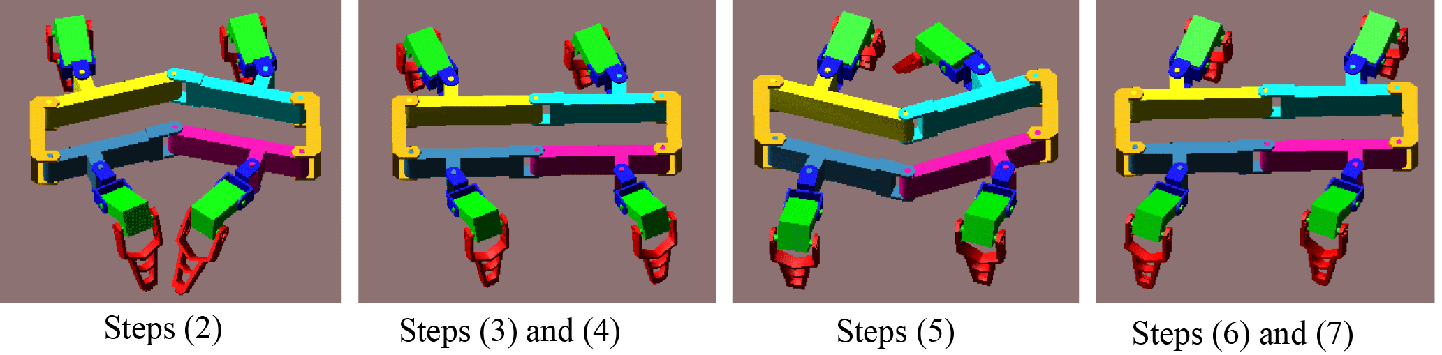
Figure 16The animation of the MetaRobot I performing the continuous static periodic gait in Adams.
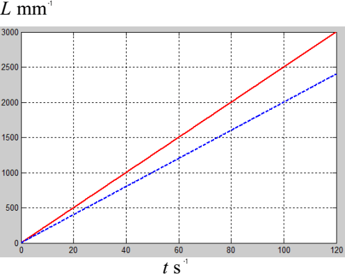
Figure 17Displacements varying with time of MetaRobot I with trunk twisting (the red solid line) and the quadruped with a single rigid body (the blue dash line).

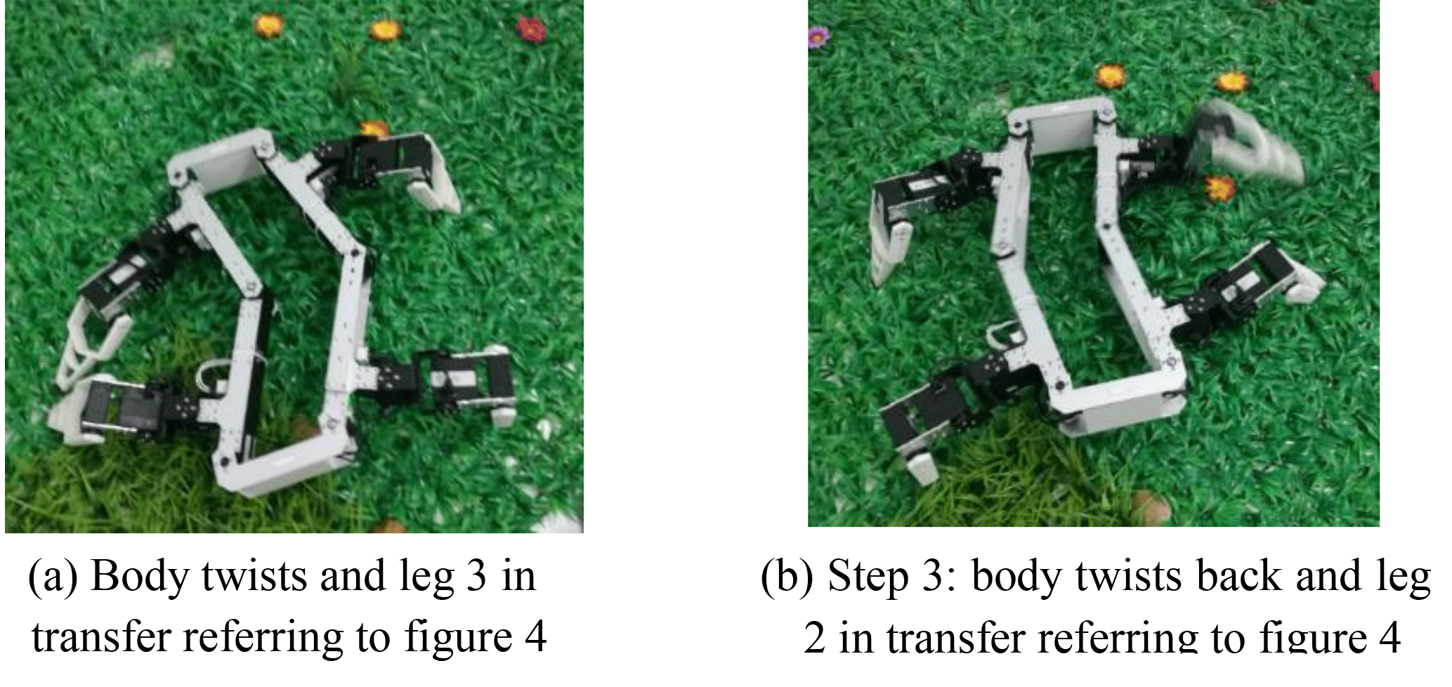
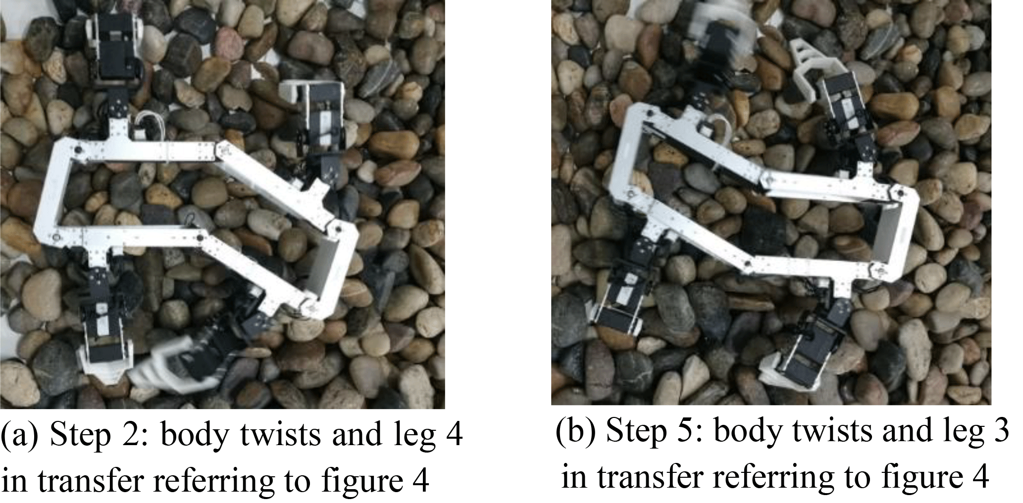
Figure 11 shows the upper limit of the stride length varying with the twisting angle θand the lateral distance r in the continuous static gait. The analysis above tells that there are two situations for the upper limit of the stride length in the continuous static gait with twisting trunks as sstride=0.8k is the Eq. (34) is not met and sstride=k if the Eq. (34) is met. Figure 12 shows the ratio between the upper limit of the stride length in the two situations varying with the twisting angle θ and the lateral distance r in the continuous static gait.
There are two plane in each figure, the upper plane corresponding to the solution set of Eq. (34) that the robot can accomplish the stride length that equal to the distance k, that sstride=k; the lower plane corresponding to the set situation that the robot cannot accomplish the upper limit of the stride length that equal to the distance k, that sstride=0.8k. The Fig. 12 also shows that for most parts of the domain of twisting angle θ and lateral distance r, the stride length with twisting trunk is 1.25 times over the stride length without twisting trunk in the continuous static gait.
For the physical meaning, Figs. 11 and 12 both show that the MetaRobot I can twist its trunk in large range of twisting angle to make its stride length or locomotion speed 1.25 times of that for the quadruped robot without twisting trunks in the continuous static gait. Since the solution set of Eq. (34) occupies most part of the domain of θ and r.
The leg that trends to go outside its reachable area can be called “dangerous leg”. During the gait cycle all footholds must be kept in their reachable areas to keep kinematic margins more than zero. To meet this, the most “dangerous leg” which is going outside its reachable area earlier than others should be investigated. Through this, it can make sure the robot gets the suit pair of r and θ to implement the gait. From Fig. 4 it is easy to see the most dangerous leg is the leg 1 when leg 4 is in transfer or the leg 2 when leg 3 is in transfer, since they are closest to the boundary of their reachable area when the leg 4 and 3 touch the ground. As a matter of fact the two situation are the same. Hence the leg 1 is chosen.
Here we first calculate the kinematic margin of leg 1 when the robot twists its trunk in situ. Then we compare this kinematic margin and the stride length to find the suitable twisting angle that make sure the kinematic margin of the “most dangerous leg” more than zero.
Figure 13 shows the kinematic margin (K=F1L1) of leg 1 after trunk twisting. The solid and dash line quadrants are the reachable areas of leg 1 before and after the trunk twisting respectively. F1 is the foothold of leg 1; J1 is the intersection point of the red line and the dash line; is the center of hip 1 after trunk twisting. The target is to find the relationship between kinematic margin of leg 1 and the twisting angle θ and lateral distance r between the hip 1 and the original foothold.
Similar to the procedure of solving increased stride length of leg 4, the variation of the x, y coordinates of leg 1 are calculated according to Eq. (3).
From Fig. 13,
Hence the kinematic margin is
The geometric parameters in Table 1 is chosen to draw the figure in Matlab that shows the tendency the kinematic margin K of leg 1 varies with θ and r in Fig. 14. It shows that for a given distance r, the kinematic margin of leg 1 decreases with the twisting angle θ first and then increases. Nevertheless for most parts in the domain of twisting angle, the kinematic margin of leg 1 is monotone decreasing with the twisting angle θ. It tells that to implement the continuous static gait, the MetaRobot I should choose its twisting angle under a suitable upper limit, or the kinematic margin of leg 1 will vanish and the gait cannot be accomplished.
Referring to steps (1) and (2) of the continuous static gait it is easy to know that to accomplish the continuous static gait the kinematic margin of the leg 1 must be at least larger than 0.125 times of the stride length. That is
The Eq. (38) gives the constraint condition that guarantees the kinematic margin. It can be solved by Matlab with numerical method through comparing K with 0.125 sstride together.
The figure illustrating the comparison is showed in Fig. 15. The domain of θ and r where K is larger than 0.125sstride (the green surface over the red surface) represents the solution set of θ and r of Eq. (38). And this domain is the feasible area that the robot can accomplish the gait with trunk twisting avoiding any les going outside their reachable area. In other domain where K is smaller than 0.125 sstride (the green surface is below the red surface), the robot cannot accomplish the gait with trunk twisting. Nevertheless, in the feasible area in the right corner of Fig. 15, the corresponding lateral distance r is too small so pairs of θ and r in this area is not suitable to be utilized to accomplish the gait. The intersecting line of the green surface and the red surface indicates the up limit of the twisting angle.
For the physical meaning, Fig. 15 tells that the MetaRobot I must twist its trunk by the angle in the feasible area to make sure the implementation of continuous static gait.
From Figs. 11, 14 and 15 the feasible pairs of the twisting angle θ and the lateral distance r can be derived, further the largest stride length can be obtained. Here we choose the pair of θ=20∘, r=100 mm to implement the continuous static gait. And then the stride length of the MetaRobot I with trunk twisting is stwist=200 mm; the stride length of the quadruped with a single rigid body is srigid=160 mm. This means that with the same time interval of one gait cycle, the speed of the metamorphic quadruped robot with twisting trunk is 1.25 times over that of the conventional quadruped robots. This can be one of the reason why the natural quadrupeds twist their trunks when moving.
A CAD model was built for MetaRobot I and a simulation was carried out in Matlab and Adams with this CAD model. Figure 16 shows the animation in Adams, which shows that the MetaRobot I can successfully perform the continuous static periodic gait.
The time interval of one gait cycle was set as 8 s. Then the speed of the MetaRobot I with trunk twisting is vtwist=25 mm s−1 while the speed of the quadruped without trunk twisting is vrigid=20 mm s−1. Figure 17 shows displacements varying with time of MetaRobot I with trunk twisting (the red solid line) and the conventional quadruped robot without trunk twisting (the blue dash line). It is convenient to find that MetaRobot I is faster than the conventional quadruped robot with a single rigid body benefited from the trunk twisting.
The physical prototype was put to walk on level terrain (Fig. 18), grasses (Fig. 19) and stones (Fig. 20) respectively. On all the terrains the MetaRobot I shows higher locomotion speed than the conventional quadruped robot with the rigid trunk.
This paper proposed a metamorphic quadruped robot with a moveable trunk, which can imitate the natural quadruped to twist its trunk, call the MetaRobot I.
From the mathematical analyses above, the twisting trunk increases the stride length of the metamorphic quadruped robot comparing to that of conventional quadruped robots. The mathematical model of the increased stride length relating to the twisting angle is given and the monotonicity of the increased stride length relating to the twisting angle is revealed.
Based on the mathematical model of the increased stride length a method to generate a continuous static gait benefit from the twisting trunk performing the increased stride length is proposed. In the gait the metamorphic quadruped performs larger stride length leading to higher locomotion speed than the conventional quadruped robots without trunk twisting. And this may be one of the reason why the natural quadrupeds always twist their trunks when they want a quick movement.
The ADAMS simulation file and prototype video can be accessed in the network disk: https://pan.baidu.com/s/1dFjhaox.
The supplement related to this article is available online at: https://doi.org/10.5194/ms-9-1-2018-supplement.
The authors declare that they have no conflict of
interest.
Edited by: Andreas Müller
Reviewed by: Peng Qi and one anonymous referee
Alexander, R. M.: The gaits of bipedal and quadrupedal animals, Int. J. Robot. Res., 3, 49–59, 1984.
Baisch, A. T., Ozcan, O., Goldberg, B., Ithier, D., and Wood, R. J.: High speed locomotion for a quadrupedal microrobot, Int. J. Robot. Res., 33, 1063–1082, 2014.
Bloss, R.: Robot walks on all four legs and carries a heavy load, Ind. Robot, 39, https://doi.org/10.1108/ir.2012.04939eaa.005, 2012.
Boaventura, T., Medrano-Cerda, G. A., Semini, C., Buchli J., and Caldwell, D. G.: Stability and performance of the compliance controller of the quadruped robot hyq, 2013 IEEE/RSJ International Conference on Intelligent Robots and Systems. IEEE, 1458–1464, 2013.
Chan, C. Y. and Liu, Y. C.: Towards a walking, turning, and jumping quadruped robot with compliant mechanisms, IEEE International Conference on Advanced Intelligent Mechatronics, IEEE, 614–620, 2016.
Chen, X., Gao, F., Qi, C., Tian, X. H., and Zhang, J. Q.: Spring parameters design for the new hydraulic actuated quadruped robot, J. Mech. Robot., 6, 021003, https://doi.org/10.1115/1.4025754, 2014.
de Santos, P. G., Garcia, E., and Estremera, J.: Quadrupedal locomotion: an introduction to the control of four-legged robots, Springer Science & Business Media, 2007.
Fukuoka, Y., Kimura, H., and Cohen, A. H.: Adaptive dynamic walking of a quadruped robot on irregular terrain based on biological concepts, Int. J. Robot. Res., 22, 187–202, 2003.
Hodgins, J. K. and Raibert, M. N.: Adjusting step length for rough terrain locomotion, IEEE T. Robotic. Autom., 7, 289–298, 1991.
Hyun, D. J., Seok, S., Lee, J., and Kim, S.: High speed trot-running: Implementation of a hierarchical controller using proprioceptive impedance control on the MIT Cheetah, Int. J. Robot. Res., 33, 1417–1445, 2014.
Koechling, J. and Marc, H.: How fast can a legged robot run?, Robots and Biological Systems: Towards a New Bionics?, Springer Berlin Heidelberg, 239–269, 1993.
Kolter, J. Z. and Ng, A. Y.: The stanford littledog: A learning and rapid replanning approach to quadruped locomotion, Int. J. Robot. Res., 30, 150–174, 2011.
Krishna, P. M. and Kumar, R. P.: Energetics of constant height level bounding in quadruped robots, Robotica, 34, 403–422, 2016.
Leeser, K. F.: Locomotion experiments on a planar quadruped robot with articulated spine, Massachusetts Institute of Technology, 1996.
McGhee, R. B. and Iswandhi, G. I.: Adaptive locomotion of a multilegged robot over rough terrain, IEEE Transactions on Systems, Man, and Cybernetics, 9, 176–182, 1979.
Pouya, S., Khodabakhsh, M., Spröwitz, A., and Ijspeert, A.: Spinal joint compliance and actuation in a simulated bounding quadruped robot, Auton. Robot., 1–16, https://doi.org/10.1007/s10514-015-9540-2, 2016.
Park, S. and Lee, Y. J.: Discontinuous zigzag gait planning of a quadruped walking robot with a waist-joint, Adv. Robotics, 21, 143–164, 2007.
Park, S. H., Kim, D. S., and Lee, Y. J.: Discontinuous spinning gait of a quadruped walking robot with waist-joint, Intelligent Robots and Systems, 2005, (IROS 2005), 2005 IEEE/RSJ International Conference on. IEEE, 2744–2749, 2005.
Raibert, M., Blankespoor, K., Nelson, G., and Playter, R.: Bigdog, the rough-terrain quadruped robot, Proceedings of the 17th World Congress, Proceedings Seoul, Korea, 17, 10822–10825, 2008.
Spröwitz, A., Tuleu, A., Vespignani, M., Ajallooeian, M., Badri, E., and Ijspeert, A. J.: Towards dynamic trot gait locomotion: Design, control, and experiments with Cheetah-cub, a compliant quadruped robot, Int. J. Robot. Res., 32, 932–950, 2013.
Wu, S., Wang, W., Wu, D., Chen, C., Zhu, P., and Liu, R.: TS20 Analysis on PL's dynamic gait for a gecko inspired climbing robot with a passive waist joint, Robotics and Biomimetics (ROBIO), 2014 IEEE International Conference on. IEEE, 943–948, 2014.
Zhen, W. K., Kang, X., Zhang, X. S., and Dai, J. S.: Gait Planning of a Novel Metamorphic Quadruped Robot, Chin. J. Mech. Eng., 11, 26–33, 2016.
- Abstract
- Introduction
- Structures of the metamorphic quadruped robot with a moveable trunk
- Design of the continuous static gait with the twisting trunk of the metamorphic quadruped robot
- The stride length increased by the twisting trunk of the metamorphic robot
- The upper limit of the stride length and corresponding twisting angle in the continuous static gait for the metamorphic quadruped robot
- The suitable twisting angle to keep kinematic margins more than zero in continuous static gait for the metamorphic quadruped robot
- The simulation and experiment of the metamorphic quadruped robot with a twisting trunk performing continuous static gait
- Conclusions
- Data availability
- Competing interests
- References
- Supplement