the Creative Commons Attribution 4.0 License.
the Creative Commons Attribution 4.0 License.
 | 18 Mar 2020
A bistable mechanism with linear negative stiffness and large in-plane lateral stiffness: design, modeling and case studies
Zhanfeng Zhou
Yongzhuo Gao
Lining Sun
Wei Dong
Zhijiang Du
To overcome the limitations of conventional bistable mechanisms, this paper proposes a novel type of bistable mechanism with linear negative stiffness and large in-plane lateral stiffness. By connecting the novel negative-stiffness mechanism in parallel with a positive-stiffness mechanism, a novel quasi-zero stiffness compliant mechanism is developed, which has good axial guidance capability and in-plane lateral anti-interference capability. Analytical models based on a comprehensive elliptic integral solution of bistable mechanism are established and then the stiffness curves of both conventional and novel bistable mechanisms are analyzed. The quasi-zero stiffness characteristic and High-Static-Low-Dynamic-Stiffness characteristic of the novel compliant mechanism are investigated and its application in constant-force mechanism and vibration isolator is discussed. A prototype with adjustable load-carrying capacity is designed and fabricated for experimental study. In the two experiments, the effectiveness of the proposed quasi-zero stiffness mechanism used in the field of constant-force output and vibration isolation is tested.


Compliant mechanisms, which gain their output motion from the deformation of flexible members, possess several attractive advantages over classical movable joints, including low cost, reduced assemble time, increased precision, no wear, no friction and no backlash (Howell, 2001). Hence, compliant mechanisms have been widely applied in many fields. A compliant mechanism that has a very low dynamic stiffness or even zero stiffness is called a quasi-zero stiffness mechanism, which is typically obtained by combining a positive-stiffness structure in parallel with a negative-stiffness mechanism. Although it has extremely low dynamic stiffness, the static stiffness of the quasi-zero stiffness mechanism is still high enough to keep a high loading capacity, that is, it has a High-Static-Low-Dynamic-Stiffness characteristic. Due to its quasi-zero stiffness characteristic, the quasi-zero stiffness mechanism can be used in many fields, especially in passive vibration isolation mechanism (Ibrahim, 2008) and constant-force mechanism (Xu, 2017a).
Passive vibration isolation is of vital importance to many precise instruments, but low frequency vibration isolation has always been a tough topic, since it will result in low static stiffness, large static displacements and low loading capacity of precise instruments (Kovacic et al., 2008a). To deal with this challenge, many quasi-zero stiffness vibration isolators have been proposed by researchers. Platus (1999) designed and analyzed a 6-DOF passive vibration isolator which used negative-stiffness mechanisms to cancel the positive stiffness of a spring suspension. Carrella et al. (2007) and Kovacic et al. (2008a) proposed a kind of nonlinear quasi-zero stiffness vibration isolator consisting of a vertical linear spring produced positive stiffness and two nonlinear pre-stressed oblique springs acted as a negative stiffness structure. Liu et al. (2013) and Huang et al. (2014) performed research on the passive nonlinear isolator which utilized Euler buckled beam as a negative stiffness corrector in parallel with a linear spring. Many researchers studied a combination of magnets as a negative-stiffness mechanism to obtain single-direction High-Static-Low-Dynamic stiffness vibration isolator (Carrella et al., 2008; Zhou and Liu, 2010; Dong et al., 2017; Zheng et al., 2018), or even low frequency multi-direction vibration isolator (Dong et al., 2018).
However, all the quasi-zero stiffness vibration isolators mentioned above have a nonlinear stiffness curve in their working ranges due to the nonlinear-negative-stiffness mechanisms they used. Nonlinear vibration isolation mechanisms have a number of disadvantages, including difficulty in obtaining mathematical expressions of stiffness, jump phenomenon degrading isolator's performance (Kovacic et al., 2008b) and easy interference from the excitation amplitude and damping (Liu et al., 2013). To overcome those issues, in this paper, a bistable compliant mechanism, which is designed based on fixed-guided beams and has constant-negative-stiffness characteristic, is applied as a negative-stiffness mechanism of a quasi-zero stiffness mechanism. Obviously, connecting a linear positive-stiffness (LPS) compliant mechanism with a linear negative-stiffness compliant mechanism in parallel can realize the linear quasi-zero stiffness of mechanisms (Xu, 2017a), as illustrated in Fig. 1. Segment OB and OD is the initial positive stiffness range, segment DE is the linear negative stiffness range, and segment BC is the linear quasi-zero stiffness range.
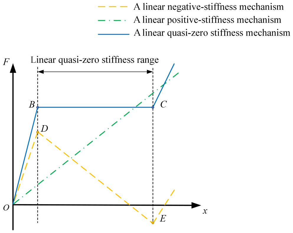
Figure 1Illustration of a linear quasi-zero stiffness mechanism consisting of a linear positive-stiffness compliant mechanism in parallel with a linear negative-stiffness compliant mechanism.
Moreover, the constant-force mechanism, achieved by combining a bistable compliant mechanism with a positive-stiffness compliant mechanism, is also an important application case of the quasi-zero stiffness mechanism. When the displacement input of the constant-force mechanism changes within its working range, the force output remains constant. The characteristic of the constant-force mechanism generates many advantages, including no requirement on driving force of the mechanism and the constant force limited to a certain threshold (Xu, 2017a). Therefore, the quasi-zero stiffness constant-force mechanism has drawn many attentions from many researchers. Dunning et al. (2013) proposed a six degrees of freedom compliant precision stage with near constant force, which implies near zero stiffness in each direction. Hao et al. (2017) designed a constant-force gripper and the constant force output of which can be adjusted to near zero by preloading the positive-stiffness mechanism. The various kinds of constant force mechanisms were developed for many different uses, such as large-stroke constant-force micro-positioning stage (Xu, 2017a), constant-force micro-gripper mechanism for biological micromanipulation (Xu, 2017b) and flexure-based constant-force XY precision positioning stage (Wang and Xu, 2017).
Obviously, in a quasi-zero stiffness mechanism, the bistable mechanism plays a very important role. The bistable mechanism based on fixed-guided beam shows great performance due to its constant negative stiffness. A variety of bistable mechanisms based on fixed-guided beam have been proposed and investigated (Kim and Ebenstein, 2012; Xu, 2017a; Kashdan et al., 2012; Ren et al., 2018). Dong et al. (2017) proposed a highly efficient bridge-type mechanism based on negative stiffness, which features compactness, symmetric structure, and high efficiency. Moreover, several mathematical modeling methods used to solve the large deformation problems of those mechanisms have been explored (Kim and Ebenstein, 2012; Holst et al., 2011; Zhang and Chen, 2013; Ma and Chen, 2016). In this paper, a comprehensive elliptic integral solution to large deformation problems (Zhang and Chen, 2013) of fixed-guided beams is employed to establish analytical models of bistable mechanisms.
Nevertheless, the conventional bistable compliant mechanism based on fixed-guided beam has a poor performance in its in-plane lateral stiffness, which will be further investigated in Sect. 2. The one-dimensional quasi-zero stiffness mechanism, whether applied as a low frequency vibration isolator or a constant-force mechanism, requires that the displacement of the mechanism can be strictly maintained in the axial working direction and there is no offset in other directions. Otherwise, the one-dimensional quasi-zero stiffness mechanism will not have good axial guidance capability in its axial working direction, which will greatly affect its performance. Hence, it's a crucial challenge to improve the conventional bistable compliant mechanism's performance in its in-plane lateral direction.
In this paper, a novel bistable compliant mechanism with a new configuration of fixed-guided beams is developed. Such mechanism has large in-plane lateral stiffness, good axial guidance capability and in-plane lateral anti-interference capability without sacrificing its axial negative stiffness, and even has a larger linear negative stiffness in its axial working direction. Moreover, the novel bistable compliant mechanism with constant negative stiffness is connected parallelly with a linear positive-stiffness compliant mechanism to obtain a linear quasi-zero stiffness mechanism, which is applied as a low frequency vibration isolator and a constant-force mechanism.
The rest of the paper is organized as follows. Section 2 analyzes in-plane axial working stiffness and in-plane lateral non-working stiffness of the conventional bistable compliant mechanism by analytical modeling and addresses the limitations of it. In Sect. 3, a novel bistable compliant mechanism with remarkable performance is developed along with its analytical modeling and performance evaluation. In Sect. 4, a novel linear quasi-zero stiffness mechanism, obtained by combining the novel bistable compliant mechanism in parallel with a positive stiffness mechanism, is designed. Section 5 investigates the application of novel linear quasi-zero stiffness mechanism in vibration isolators and constant-force mechanisms, and then describes the design of prototype and the experimental testing of the linear quasi-zero stiffness mechanism. Section 6 concludes this paper.
A conventional bistable compliant mechanism consists of four inclined fixed-guided beams, which is shown in Fig. 2. Four inclined fixed-guided beams are arranged symmetrically in two sides of the moving platform and have an angle β with respect to y-axis. When the moving platform is driven axially by the vertical force F, the guided end of each fixed-guided beam, together with the moving platform, will move downward in the vertical direction. The external force exerted by each beam on the moving platform is symmetrical and equal due to the symmetry of the mechanism, so the movement of the moving platform is strictly axial downward, which is illustrated in Fig. 3a. During the movement of platform, the angles of fixed end and guided end of each beam remain constant. The deformation of each fixed–guided beam is illustrated in Fig. 3b, where L is the beam's length, Ψ is end force angle with respect to x-axis, ηP is the end force and M0 is the end moment. Next, an analytical model of the conventional bistable compliant mechanism will be derived.
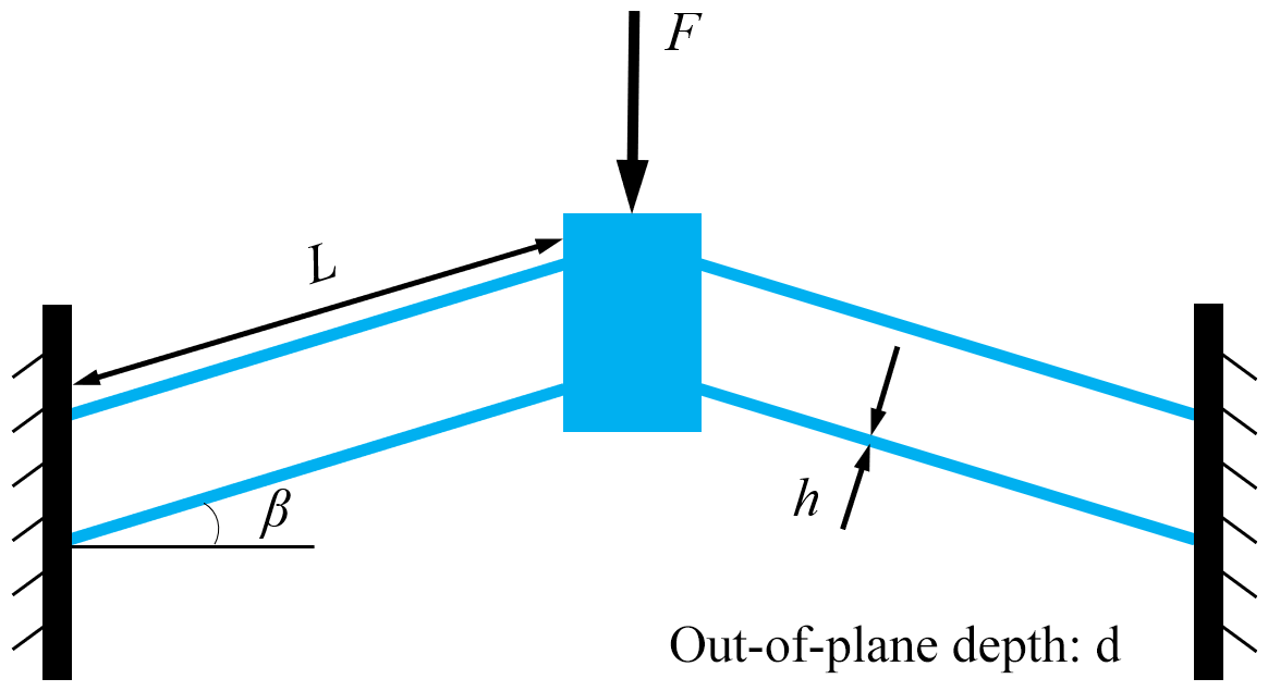
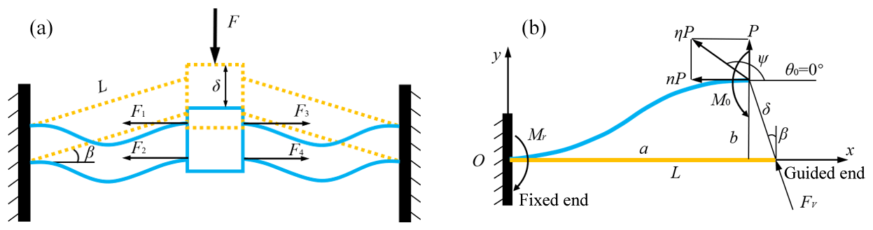
Figure 3(a) Deformation and internal force of the bistable mechanism driven axially by the vertical force. (b) The deformation and external force of each fixed–guided beam during the movement of the bistable mechanism.
2.1 Analytical modeling of the conventional bistable mechanism
A large deformation of each fixed-guided beam of conventional bistable compliant mechanism is generated, so the small deformation theory cannot be employed in this case. Many methods can be used to solve the large deformation problems of compliant mechanisms, such as the chain algorithm (Coulter and Miller, 1988; Chase et al., 2011), pseudo-rigid-body model (Howell, 2001; Jensen and Howell, 2003), finite element model (Masters and Howell, 2003), chained beam-constraint-model (Ma and Chen, 2016) and the elliptic integral solution (Holst et al., 2011; Kim et al., 2012). Ma and Chen (2016) have compared many different models for the bistable compliant mechanism and applied chained beam-constraint-model to solve large deflection problems. Zhang and Chen (2013) have studied comprehensive elliptic integral solution to model the fixed-guided beam and analyzed the bistable mechanism. The chained beam-constraint-model (Ma and Chen, 2016) is more accurate in capturing the first peak of the bistable curve and performs well when axial deflections cannot be neglected. In contrast, comprehensive elliptic integral solution (Zhang and Chen, 2013) is more efficient in solving the linear negative stiffness curve because of their closed-form solutions. In this paper, the linear axial negative stiffness and in-plane lateral stiffness of compliant bistable mechanism will be studied further, thus the comprehensive elliptic integral solution (Zhang and Chen, 2013) is employed.
For the deformed fixed-guided beam shown in Fig. 3b, the coordinates of the guided end are (a, b), and the end force ηP can be divided into a vertical component P and a horizontal component nP.
Since the angles of the guided end and the fixed end of the beam remain zero constantly, there is at least one inflection point on the deflected beam. We use m to indicate the number of inflection points on the fixed-guide beam. In most cases, the inflection points of the fixed-guide beam of bistable mechanisms after deformation will not exceed two, that is, the range of the number of inflection points is 1 or 2. In addition, the fixed-guide beams with different number of inflection points correspond to different buckling modes: the first buckling mode and the second buckling mode represent the fixed-guide beams of one inflection point and two inflection point, respectively. Most importantly, at each inflection point, the curvature of the fixed-guide beam will change the sign, which also implies the change of the sign of beam internal moment.
Then the comprehensive elliptic integral solution of the fixed-guided beam can be expressed as follows,
where α is the nondimensional value of the beam length, Sr is the sign of the moment at the fixed end of the beam, a∕L and b∕L are the nondimensional coordinates of the beam guided end along the x- and y-axes, respectively and can be given as:
where m is the number of inflection points and γ1 is the amplitude of the elliptic integral corresponding to the fixed end of the beam, which can be expressed as
In addition, λ can be expressed as
where κ is the load ratio defined as
where M0 is the moment of the beam guided end, E and I denote the Young's modulus of material and the second-order moment of inertia of the fixed-guided beam, respectively. αis the nondimensional value of the beam length L and be expressed as,
Then, Sr is defined as the sign of Mr, which is the moment of the fixed end of the beam, as shown in Fig. 3b. Also, S0 is defined as the sign of M0. Therefore, it can be formulated as below,
F(γ,t) and E(γ,t) are the incomplete elliptic integrals of the first and second kind respectively, which are defined as
where t and γ is modulus and the amplitude of the elliptic integral respectively and specifically, γ1 is the amplitude of the elliptic integral corresponding to the fixed end of the beam. When , Eqs. (12) and (13) become the complete elliptic integrals of the first and second kinds which are F(t) and E(t) respectively.
As for the fixed-guided beam, the displacement that the beam end moves in the guided direction is δ, which is shown in Fig. 3b. β is the inclined angle of the beam guided end with respect to y-axis. Then, the coordinates of the beam guided end (a, b), can be obtained as follows
When the coordinates of the beam guided end (a, b) are known, we can numerically solve the force and moment of the beam end (P, n, M0). Given the initial value of n and κ, a numerical iteration process of Eqs. (2) and (3) can be employed in order to obtain the value of n and κ. Substitutingn and κ into Eqs. (1), (9) and (10), the value of P and M0 can be calculated finally. The above calculation process can be easily solved using MATLAB.
Based on above analytical model, the driving force of a single fixed-guided beam shown in Fig. 3a can be expressed as
Since the conventional bistable mechanism consists of four fixed-guided beams shown in Fig. 3b, the axial external force of the mechanism is given as
With the above analytical model of the fixed-guided beam, the performance of the bistable mechanism axial movement is evaluated in Sect. 2.3.
2.2 Analytical modeling of lateral stiffness
In addition to the previous solutions to solve the in-plane axial movement of the conventional bistable mechanism, the model of in-plane lateral stiffness must be solved in order to evaluate whether the conventional bistable mechanism has a well-performed axial guidance capability and lateral anti-interference capability. The in-plane lateral direction is perpendicular to the axial direction of the bistable mechanism.
During the axial movement of the bistable mechanism, the deflection of each fixed-guided beam is gradually increased at the beginning. When the fixed and guided ends of each fixed-guided beam are at the same horizontal line, the deflection of each beam reaches a maximum, and then will gradually reduce. At that point, each beam has the largest external force which is strictly horizontal without component force in the axial direction, as shown in Fig. 3a. At this time, the bistable mechanism is in an unstable equilibrium state, and each beam has the largest deflection in the range of motion, so the mechanism is easy to perform lateral motion and is susceptible to lateral interference.
In Sect. 2.3, we will investigate that the lateral stiffness of the bistable mechanism is not large enough to achieve a good axial guidance capability and lateral anti-interference capability, especially at the unstable equilibrium point. Before that, the analytical modeling of the in-plane lateral stiffness of the bistable mechanism at the unstable equilibrium point needs to be derived first as follows.
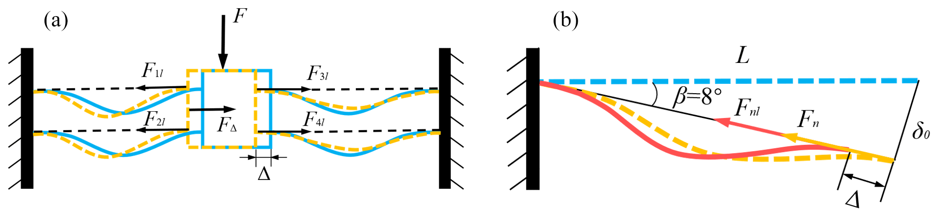
Figure 4(a) The relationship of in-plane lateral force and deformation of the conventional bistable mechanism at the unstable equilibrium point. (b) The external force and deformation of each fixed-guided beam of the bistable mechanism with in-plane lateral deviation at the unstable equilibrium point.
The in-plane lateral force and displacement of the bistable mechanism at the unstable equilibrium point is shown in Fig. 4a. The bistable mechanism is subjected to lateral force FΔ, and the resulting lateral displacement of the moving platform is Δ. At the same time, the external force and deformation of each fixed-guided beam of the bistable mechanism with in-plane lateral deviation is shown in Fig. 4b.
At the unstable equilibrium point, the axial displacement of the bistable mechanism is given as
Substituting Eq. (18) into Eqs. (14) and (15) gives
At this case, the coordinates of beam guided end (a, b) is known, then we can use the elliptic integral derived in Sect. 2.1 to solve the resulting force and moment of the beam guided end (P, n, M0). Therefore, in Fig. 4b, the external force of the beam from the guided end to the fixed end can be expressed as below.
The lateral displacement of each fixed-guided beam is Δ, as shown in Fig. 4b. Then, the coordinates of the beam guided end change to (al, bl), which is given as
The force and moment of the beam end that is calculated by the elliptic integral in Sect. 2.1 also change to (Pl, nl, M0l). Thus, the resultant force of the beam from the guided end to the fixed end after the lateral displacement can be written as
The amount of change in the force before and after lateral displacement is
As shown in Fig. 4b, after the lateral displacement of the beam, the direction of the lateral resultant force of each fixed-guided beam does not change, but the value changes from Fn to Fnl. Since the fixed-guided beam is arranged symmetrically in two sides of the moving platform, the followings can be formulated.
When the in-plane lateral displacement of the bistable mechanism does not occur, the guided end force of each fixed-guided beam must be equal.
Then the external driving force of the bistable mechanism in the lateral direction, as shown in Fig. 4b, can be expressed as
Substituting Eqs. (26)–(30) into Eq. (31) yields
where,
Based on the above derived analytical model, the performance of in-plane lateral stiffness of bistable mechanism is evaluated in Sect. 2.3.
2.3 Performance evaluation
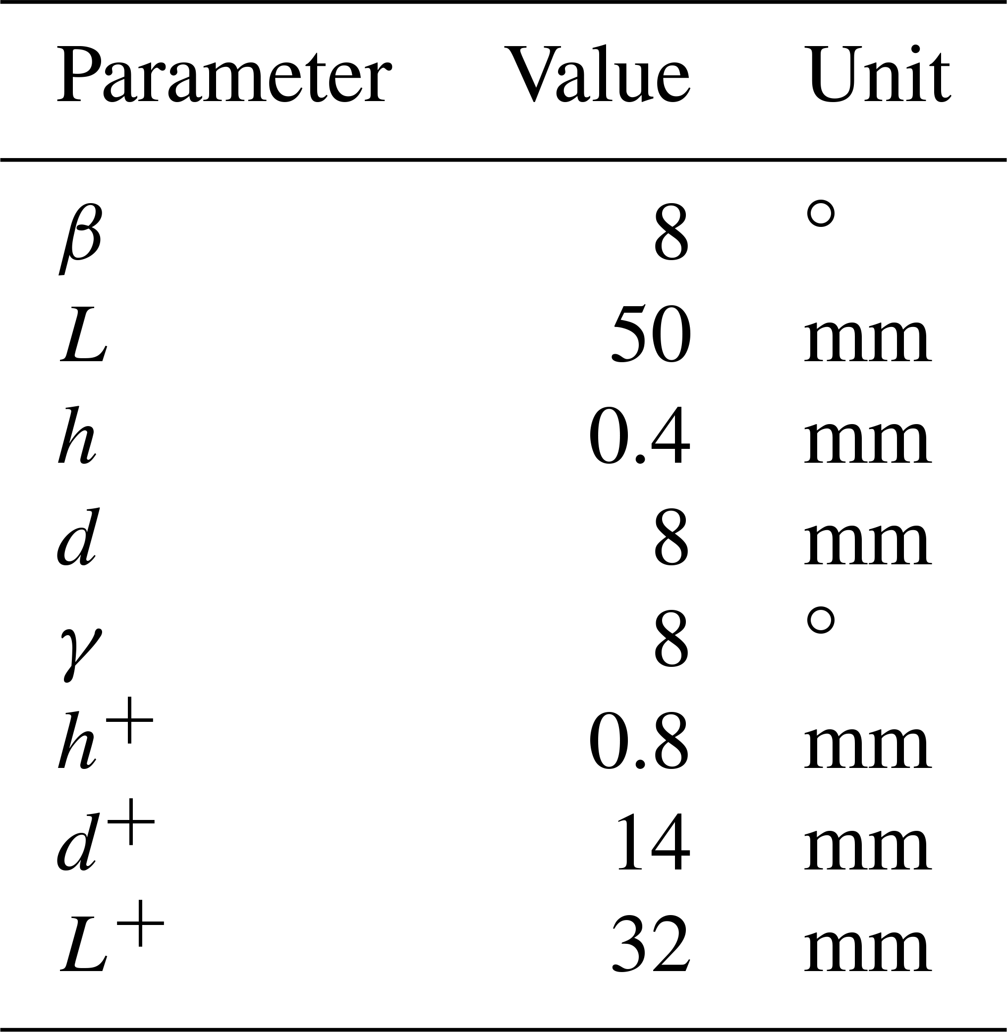
In order to evaluate the performance of the bistable mechanism quantitatively, the parameters of the fixed-guided beam are first determined identically, including the inclined angle β, length L, in-plane width h, out-of-plane depth d and Young's modulus E, as listed in Table 1.

Given the value of the axial displacement of the bistable mechanism moving platform δ, the driving force of the moving platform F can be calculated numerically by MATLAB using the analytical model in Sect. 2.1. Then, with the parameters shown in Table 1, the axial force F versus displacement δ of the conventional bistable compliant mechanism can be obtained, which is shown in Fig. 5. Obviously, the axial force–displacement curve can be divided into three segments: the segment AB is the initial buckling range, the segment BD is the constant negative stiffness range, and the segment DE is positive stiffness range. The main working range of the bistable negative stiffness mechanism is the segment BD which has an excellent linear negative stiffness characteristic. In Fig. 5, the value of the linear negative stiffness can be calculated, which is N mm−1.
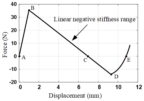
Figure 5The axial force–displacement curve of the conventional bistable negative-stiffness compliant mechanism.
It can be concluded from Figs. 1 and 5 that if the linear negative stiffness of the mechanism is large enough and connected in parallel with positive stiffness of the same magnitude, the maximum load carrying capacity or the constant force output of the quasi-zero stiffness mechanism will be great. Therefore, the new bistable mechanism must be designed to enhance the value of the linear negative stiffness, which will be discussed in Sect. 3.
Next, we analyze the in-plane lateral stiffness of the conventional bistable mechanism based on the analytical model derived in Sect. 2.2. In the case that the fixed and guided ends of each beam are at the same horizontal line, which implies the unstable equilibrium point, as shown in Fig. 4a, the in-plane lateral displacement of the moving platform Δ is differentiated within the allowable range, and then the value of lateral diving force FΔ corresponding to Δ can be obtained. With the parameters shown in Table 1, the in-plane lateral force–displacement curve of the bistable mechanism is shown in Fig. 6. It can be observed from Fig. 6 that in the first segment OA, the lateral positive stiffness is very small, then the linear lateral positive stiffness increases slowly. Therefore, the conventional bistable mechanism has a poor performance in its axial guidance capability and lateral anti-interference capability. Figure 6 also shows that after the point A, the lateral positive stiffness of the mechanism increases faster and faster, and finally tends to infinity. Such phenomenon can be explained as follows. When the lateral displacement of the mechanism increases, on one side of the moving platform, fixed-guided beams becomes more and more buckled, but on the other side, fixed-guided beams gradually change from buckled to stretched and finally even stretched to the limiting position. The external force of the fixed-guided stretched beam is far greater than that of the fixed-guided buckled beam.
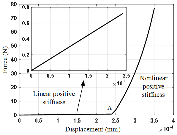
Figure 6In-plane lateral force–displacement curve of the conventional bistable mechanism at the unstable equilibrium point.
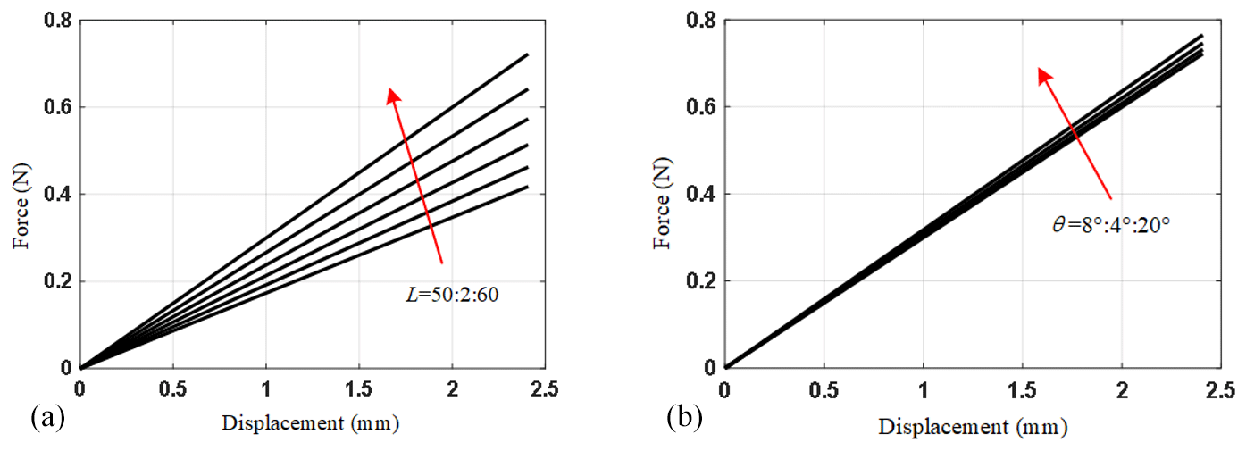
Figure 7Variation tendencies of segment OA of the in-plane lateral force–displacement curve of the conventional bistable mechanism at the unstable equilibrium point. (a) The beam length L is varied; (b) the inclined angle β is varied.
Then, the parametric analysis of the lateral positive stiffness of bistable mechanism is conducted using the analytical model in Sect. 2.2. There are two main parameters affecting the lateral positive stiffness: the beam length L and the inclined angle β of the fixed guide beam with respect to x-axis. When one parameter changes and the other parameters remains constant, the variation tendencies of the segment OA of the in-plane lateral force–displacement curve are illustrated in Fig. 7. It is observed from Fig. 7 that when the beam length L decreases or the inclined angle β increases, the linear lateral positive stiffness of the bistable mechanism at the unstable equilibrium point increases. However, it is obvious that the influence of the inclined angle β on the lateral positive stiffness is actually small.
In order to analyze the characteristics of the lateral positive stiffness of the bistable mechanism more accurately, we change the beam length L of the bistable mechanism and then calculate the values of the axial constant negative stiffness and the in-plane lateral constant positive stiffness of the mechanism. The results are listed in Table 2. By analyzing the data in Table 2, we can easily find that the value of the constant lateral positive stiffness of the bistable mechanism at the unstable equilibrium point is ever smaller than the linear negative stiffness. Most importantly, the value of constant negative stiffness is near 2 times larger than that of the constant positive stiffness.
Table 2Values of the axial negative stiffness and the in-plane lateral positive stiffness at the unstable equilibrium point of the bistable mechanism when changing the beam length L.
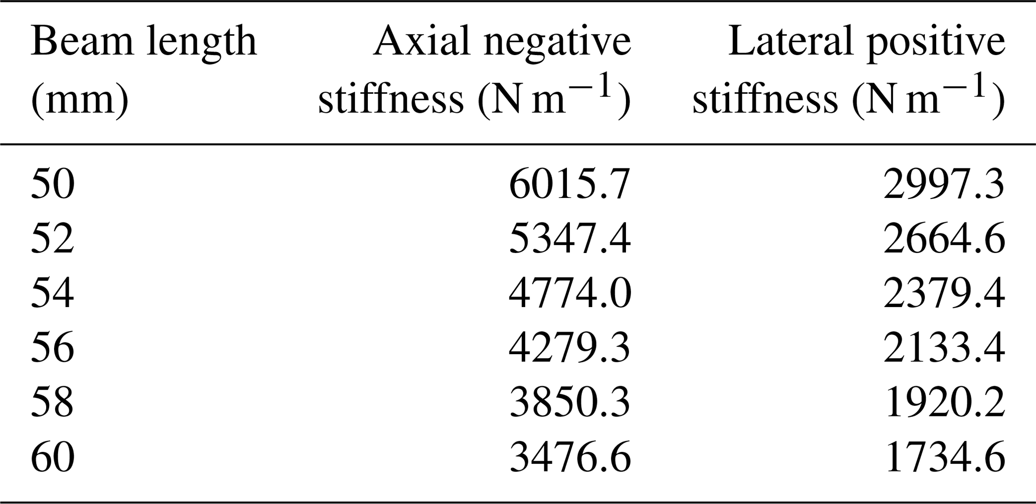
The conclusion drawn from the above parts means that the lateral positive stiffness of the conventional bistable mechanism is very small so that the mechanism will perform a bad axial guidance capability and lateral anti-interference capability.
Therefore, in order to overcome these shortcomings, a novel bistable mechanism with large in-plane lateral positive stiffness must be designed, which is discussed in Sect. 3.
3.1 Configuration of novel bistable compliant mechanism
The conventional bistable compliant mechanism consists of four fixed-guided beams, as is shown in Fig. 2.
In order to increase the lateral stiffness of the conventional bistable mechanism, the configuration of the fixed-guided beams of the conventional bistable mechanism is expanded from being distributed on both sides of the moving platform to four sides, and then a novel bistable mechanism, which is called Type A bistable mechanism, is proposed, as shown in Fig. 8b.
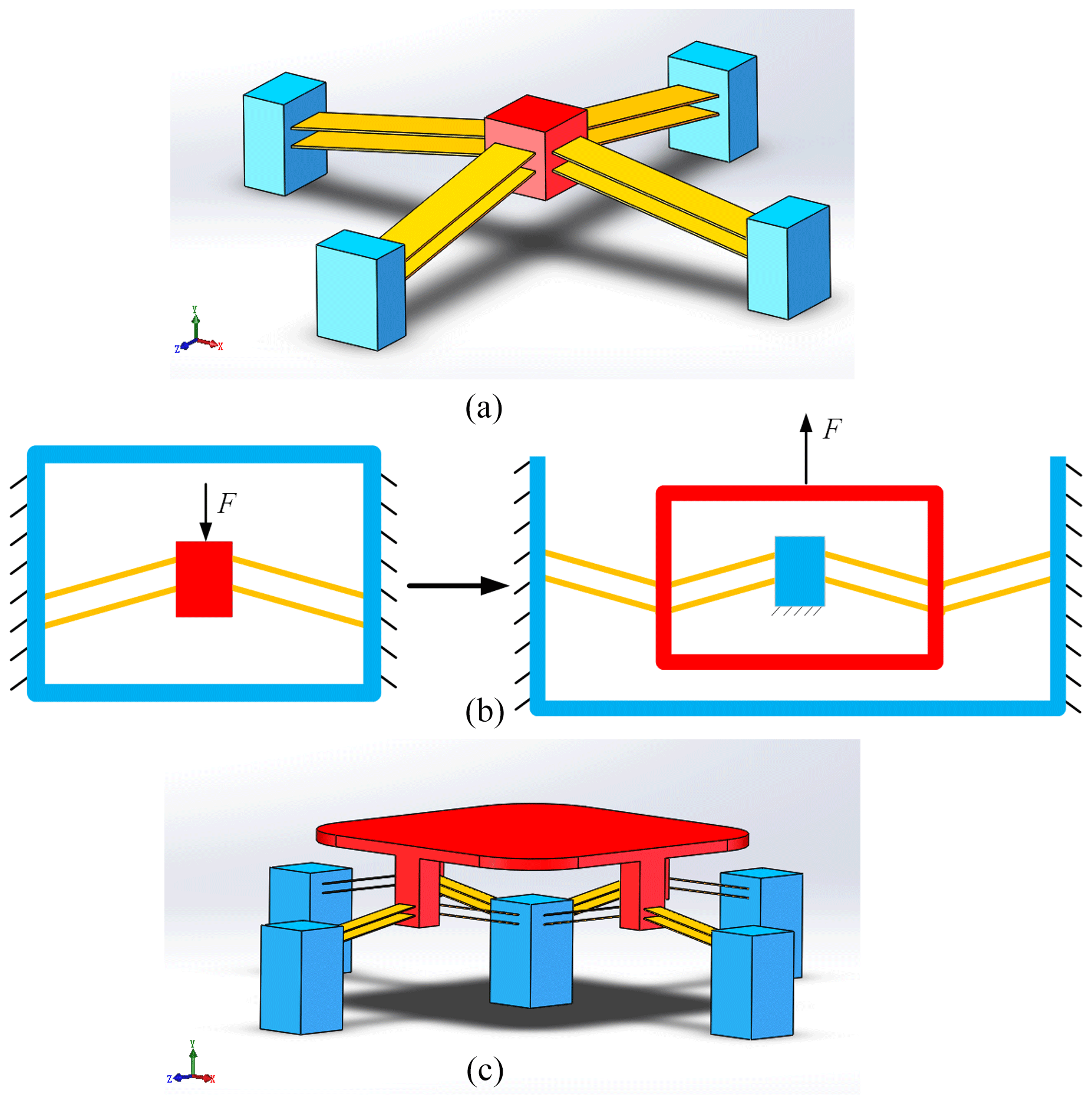
Figure 8(a) Three-dimensional model of the Type A bistable mechanism. (b) The optimizing design process from the type A bistable mechanism to the type B bistable mechanism. (c) Three-dimensional model of the newly designed Type B bistable mechanism. The red, yellow and blue parts represent the moving platform, the fixed-guided beams and the fixed base, respectively.
The Type A bistable mechanism has a very good performance in axial guidance capability and lateral anti-interference capability. The design ideas for the new type of mechanism are described as follows. The buckling of each fixed-guided beam can only occur in one plane, that is to say, each beam has two degrees of freedom during buckling. However, in the out-of-plane direction, which is perpendicular to the plane of two degrees of freedom, the fixed-guided beam has very large stiffness and can hardly deform. Such characteristic provides a limit on the degree of freedom in the out-of-plane direction. Therefore, if each fixed-guide beam is symmetrically arranged according to the configuration shown in Fig. 2, the bistable mechanism must have two degrees of freedom in one plane. Nevertheless, if each fixed-guided beam is connected in parallel on four sides of the moving platform, as shown in Fig. 8a, the two translational degrees of freedom in the horizontal plane of the moving platform are suppressed. Thus, the Type A bistable mechanism only has one degree of freedom in the axial direction. As a consequence, the stiffness in the horizontal plane (the horizontal stiffness) of the Type A bistable mechanism becomes very large so that the mechanism can resist very large horizontal interferences and has a good axial guidance capability.
Then, in order to improve the load-carrying capacity of the quasi-zero stiffness mechanism which consists of the negative-stiffness bistable mechanism in parallel with the positive-stiffness mechanism, the constant negative stiffness of the bistable mechanism is required to be as large as possible. The positive stiffness should be of the same magnitude as the constant negative stiffness. Therefore, it is necessary to carry out further innovative design based on the Type A bistable mechanism.
By further innovative design of the Type A bistable mechanism, we can obtain the Type B bistable mechanism. The optimizing design process from the type A bistable mechanism to the type B bistable mechanism is shown in Fig. 8b and detailed as follows. The moving platform of the Type A bistable mechanism changes into a fixed base, and the four surrounding fixed bases turn into a moving platform, i.e., the moving platform and the four surrounding fixed bases of the Type A bistable mechanism are reversed. Then, four pairs of fixed-guided beams are added parallelly around the bistable mechanism and a new fixed base to which the newly-added fixed-guided beams are attached is arranged on the outermost of the novel bistable mechanism. Finally, the newly designed Type B bistable mechanism is obtained, as shown in Fig. 8c.
In the design process above, with the number of fixed-guiding beams increased, the Type B bistable mechanism not only has great horizontal stiffness to ensure good axial guidance capability and horizontal anti-interference capability, but also improve the axial negative stiffness remarkably. More specifically, since the Type B bistable mechanism consists of sixteen fixed-guided beams, as shown in Fig. 8c, the axial external force of the mechanism is given as
With the parameters of fixed-guided beams shown in Table 1, the axial force FB versus displacement δB of the Type B bistable compliant mechanism can be obtained, which is shown in Fig. 9. Obviously, the new design enlarges the absolute value of constant negative stiffness by twice in comparison with the conventional bistable mechanism. Hence, the load-carrying capacity of the quasi-zero mechanism combined of the Type B bistable compliant mechanism in parallel with positive-stiffness mechanism can also be enhanced greatly.
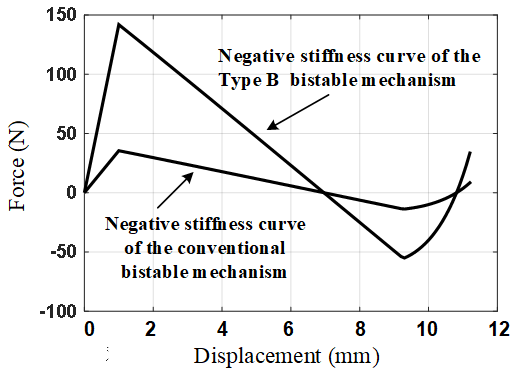
Figure 9The axial force–displacement curve of the Type B bistable mechanism and of conventional bistable mechanism.
3.2 Model and analysis of maximum stress
When the axial negative stiffness of the Type B bistable mechanism is increased, each fixed-guided beam must endure larger force. If the internal stress in the beam is larger than the limit stress of the material, it will cause the beam to break. Therefore, it is necessary to calculate the maximum internal tensile stress of the fixed-guided beams during the movement, and then evaluate whether the fixed-guided beam will break according to the maximum allowable stress of the material.
The maximum internal tensile stress of the fixed-guided beam during the motion occurs when the fixed-guided beam is maximally deformed. The maximum normal stress the fixed-guided beam can be expressed as
where Nmax is the maximum internal normal force along the beam, and Mmax is the largest internal moment. At the unstable equilibrium point during the mechanism vertical movement, the distance between the guided end of each beam and the fixed end is minimal, so the deformation of each fixed-guided beam is largest. The internal normal force of the fixed-guided beam is constantly compressive, so the maximum internal normal force along the beam can be calculated as below.
According to the Euler beam theory, the largest internal moment occurs at the point that has the largest curvature of the beam. The largest internal moment along the beam can be derived as below.
Substituting Eqs. (37) and (38) into Eq. (36) results in the expression of maximum stress.
The above calculation of the maximum stress can be used to verify whether the parameters of the linear negative-stiffness mechanism satisfy the material strength criterion.
In order to achieve a quasi-zero stiffness compliant mechanism, the positive-stiffness and negative-stiffness mechanisms need to be connected in parallel, and the magnitude of the stiffness absolute value of the two mechanisms should be the same. Therefore, with the novel Type B bistable mechanism proposed in Sect. 3.1, a positive-stiffness mechanism should be discussed in Sect. 4.1.
4.1 Linear positive-stiffness mechanism analysis
In previous designs, leaf flexure is always used as positive stiffness mechanism (Wang and Xu, 2017). However, the shortages of the leaf flexure are obvious, like the size of the slender leaf and the stress stiffening phenomenon (Wang and Xu, 2016). In this paper, in order to increase the stroke of positive stiffness mechanism in the axial direction, we use a V-shaped positive-stiffness mechanism which is similar to the compound parallelogram flexure but with a larger vertical stroke. The structure of the V-shaped positive-stiffness mechanism is shown in Fig. 10. The base of the V-shaped mechanism is fixed at the bottom and the tilted flexure beams are arranged symmetrically on two sides of the mechanism in a V-shaped configuration.
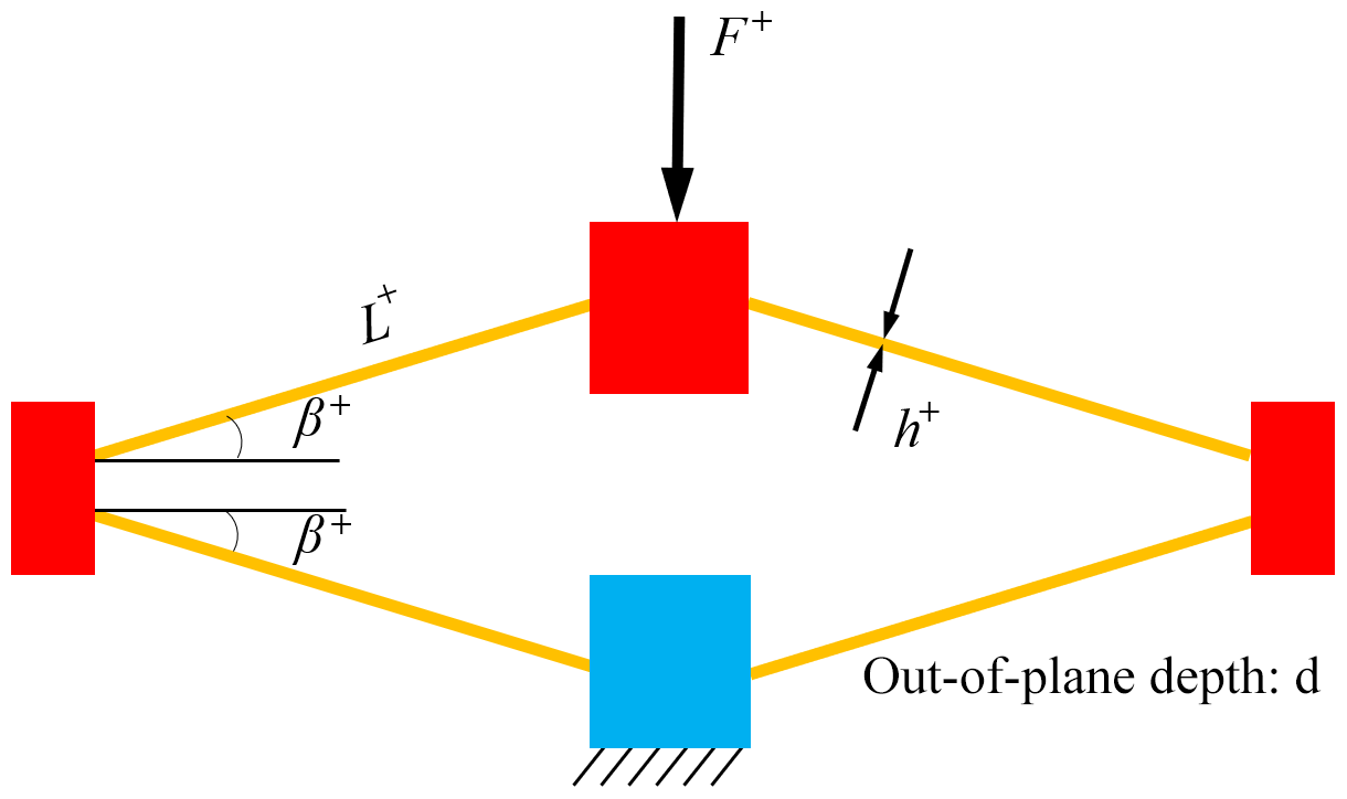
Figure 10The structure of the V-shaped positive-stiffness mechanism. The red, yellow and blue parts represent the moving platforms, the tilted flexure beams and the fixed base, respectively.
When the uppermost moving platform moves axially downward, the tilted flexure beams will be compressed, but at the same time, the connecting ends of two tiled beams on both sides will produce corresponding outward movement. Therefore, each tilted flexure beam can be analyzed by small deformation theory and the stiffness of the V-shaped mechanism can be calculated in the same way to the stiffness of compound parallelogram flexure (CPF) which is discussed by Xu (2012). The expression of the constant positive stiffness of the V-shaped mechanism is formulated as below,
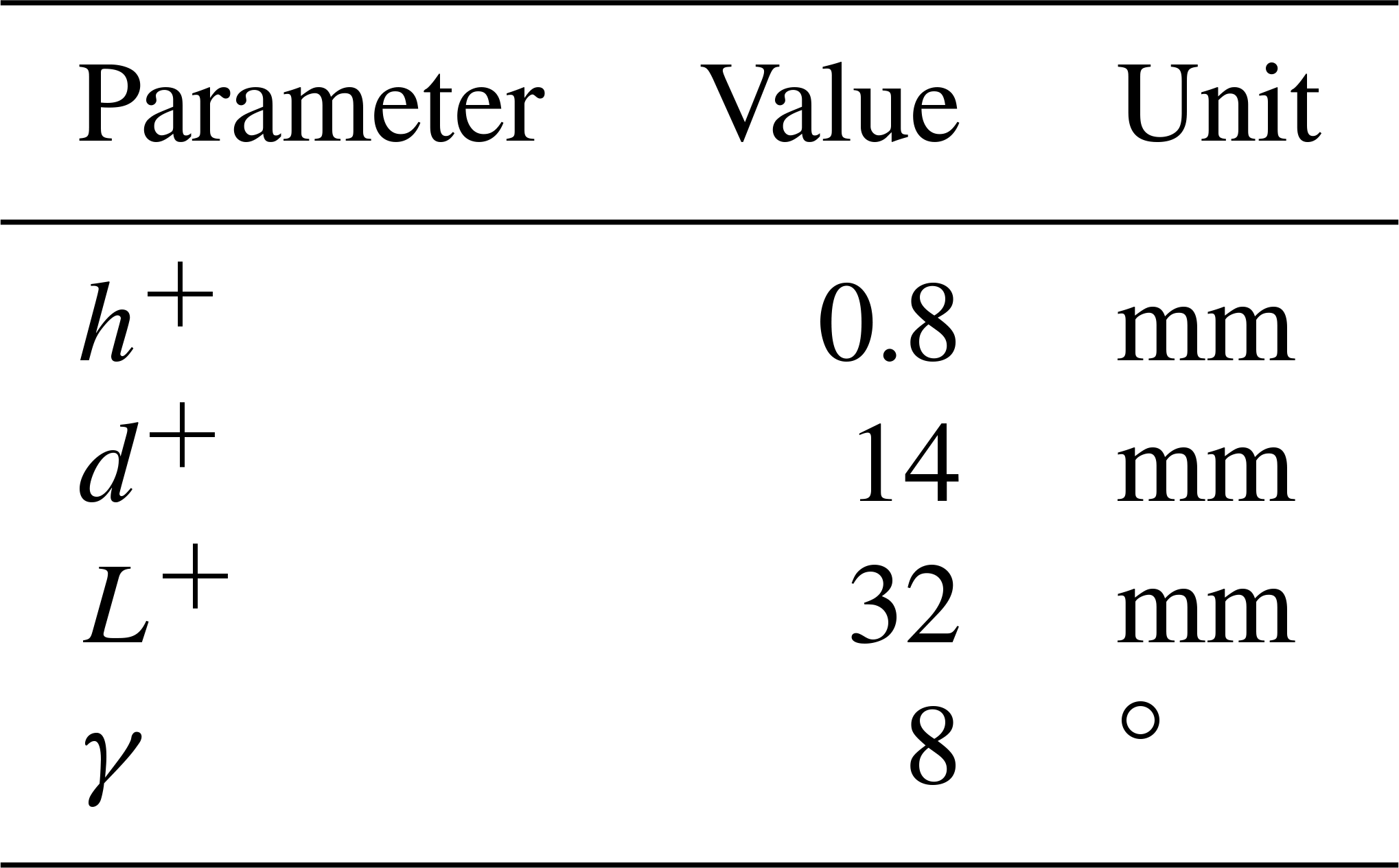
where h+, d+ and L+ represent the in-plane width, out-plane thickness and length, respectively.
4.2 Conceptual design
The quasi-zero stiffness compliant mechanism can be designed by connecting the novel Type B negative-stiffness compliant mechanism in parallel with positive-stiffness mechanism. As shown in Fig. 11, the V-shape positive-stiffness mechanism is attached to the center of the Type B bistable mechanism while the base and the moving platform of the two mechanisms are also joined together. When the upper moving platform of the Type B bistable compliant mechanism moves axially downward, the moving platform of positive-stiffness mechanism has axially downward motion simultaneously. Hence, the positive-stiffness and negative-stiffness mechanisms will work in parallel and the quasi-zero stiffness compliant mechanism can be achieved.

Figure 11The conceptual design of the quasi-zero stiffness compliant mechanism. The red, yellow and blue parts represent the moving platforms, the tilted flexure beams and the fixed bases, respectively.
4.3 Parametric design
In order to achieve the quasi-zero stiffness, the negative stiffness Kn must be equal to the positive stiffness Kv. The parameters of the Type B bistable mechanism is given in Table 2, then the value of constant negative stiffness can be calculated using the negative stiffness curve shown in Fig. 9. The value of constant negative stiffness of the Type B bistable mechanism is about −24.063 N mm−1. Therefore, the positive stiffness should be equal to or slightly larger than 24.063 N mm−1. With the formula Eq. (37) of the positive stiffness of the V-shaped mechanism, the parameters of the positive-stiffness mechanism are designed in Table 3.
4.4 Performance evaluation
According to models and parameters above, the stiffness curve of the V-shaped positive-stiffness and the Type B negative-stiffness mechanism can be obtained, as shown in Fig. 12. Then the stiffness curve of the quasi-zero stiffness mechanism can be obtained in Fig. 12. The stiffness curve of the quasi-zero stiffness mechanism in the working range is close to horizontal, that is, the stiffness is close to zero.
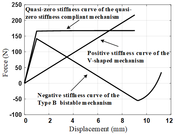
Figure 12The force–displacement curve of the Type B bistable linear negative-stiffness mechanism, V-shaped positive-stiffness mechanism and quasi-zero stiffness compliant mechanism.
When the axial displacement occurs, the force has no changes and remains very large. Therefore, this quasi-zero stiffness mechanism has excellent characteristics as a constant force mechanism. Moreover, if the quasi-zero stiffness mechanism is used as a vibration isolator, it will have near zero dynamic stiffness and therefore has a good low-frequency vibration isolation performance. Besides the good dynamic characteristics, the load-carrying capacity of the vibration isolator is still very large, that is, the static stiffness of it is large enough. As shown in Fig. 12, the vibration isolator can carry a load of about 170 N. In conclusion, the quasi-zero stiffness mechanism as a vibration isolator has good high-static-low-dynamic-stiffness characteristics.
5.1 Prototype fabrication
A prototype of the quasi-zero stiffness mechanism has been designed in detail and fabricated to demonstrate the performance of the proposed design. The tilted flexure beams are composed of beryllium bronze, while the other parts of the prototype are made of Al-6061. The Young's modulus of beryllium bronze is very close to that of titanium alloy, and such material is easy to process.
A computer-aided design (CAD) model of the proposed quasi-zero stiffness mechanism is shown in Fig. 13a. The positive-stiffness mechanism is connected in parallel at the center of the Type B bistable negative-stiffness mechanism to obtain the quasi-zero stiffness platform. The tilted leaf springs in both positive-stiffness and negative-stiffness mechanisms are standard size thin beams manufactured separately in order to improve dimensional accuracy. The end of each leaf spring is fully constrained by two wedge-shaped blocks, which is shown in Fig. 13b. The wedge-shaped pressure block is pressed by screwing the bolts, and the pressure is amplified by the wedge surface, thus the beams are stably tightened.
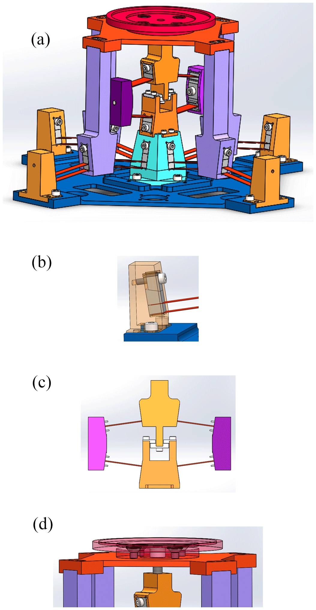
Figure 13(a) Three-dimensional computer-aided design model of the proposed quasi-zero stiffness mechanism. (b) Leaf springs fully constrained by the wedge-shaped blocks. (c) Limit structure between the moving platform and the fixed base of the positive-stiffness mechanism. (d) The bolt and the limit cover connecting the positive-stiffness and negative-stiffness mechanism tightly.
From the quasi-zero stiffness curve in Fig. 12, it is obvious that although its force output or load carrying capacity is large and the stiffness is close to zero, the value of the constant force output or load-bearing capacity in the range of zero stiffness cannot change. Therefore, we need to optimize the design of the prototype so that it can be adjusted to achieve quasi-zero stiffness at any force output. First, a limit structure is designed between the moving platform and the fixed base of the positive-stiffness mechanism to limit the moving platform to only move axially downward but not upward, as shown in Fig. 13c. Second, the moving platform of the positive-stiffness and negative-stiffness mechanism is connected by a bolt, as shown in Fig. 13d. When the bolt is screwed in, the positive-stiffness mechanism cannot move axially upward due to the limit structure, so that only the moving platform of the negative-stiffness mechanism will move downward. This is equivalent to applying a preload displacement to the negative-stiffness mechanism, thus achieving adjustment of the constant force output or load-carrying capacity. Finally, a limit cover is designed on the bolt, and serves as a load-carrying platform, as shown in Fig. 13d. When the moving platform moves upward or downward, the positive-stiffness and negative-stiffness mechanism can be tightly connected due to the limit cover.
When the bolt is not screwed in, it can be seen from Fig. 12 that the quasi-zero stiffness mechanism has the maximum constant force output or load-carrying capacity of 160 N. When the bolt is screwed in, the negative-stiffness mechanism has a preload displacement, which corresponds to the negative stiffness curve moving horizontally to the left for a distance. The quasi-zero stiffness curve also changes accordingly, as shown in Fig. 14. When the bolt is screwed into different displacements, different quasi-zero stiffness curves can be obtained, which corresponds to different force output or load-carrying capacity. When the bolt is screwed into 3 mm, the negative stiffness curve moves 3 mm to the left along the horizontal axis, and thus the constant force output of the quasi-zero stiffness mechanism is 100 N. When the bolt is screwed into 5 mm, the constant force output is 50 N.

Figure 14Different quasi-zero stiffness curves with the bolt screwing into different displacements. (a) The bolt is screwed into 3 mm. (b) The bolt is screwed into 5 mm.
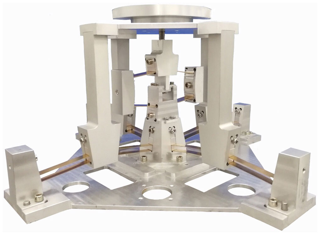
According to the three-dimensional CAD model of the mechanism designed above, the prototype platform is fabricated as depicted in Fig. 15. The main parameters of the quasi-zero stiffness stage are listed in Table 4.
5.2 Test 1: force–displacement curve (stiffness curve) and constant force output of the prototype
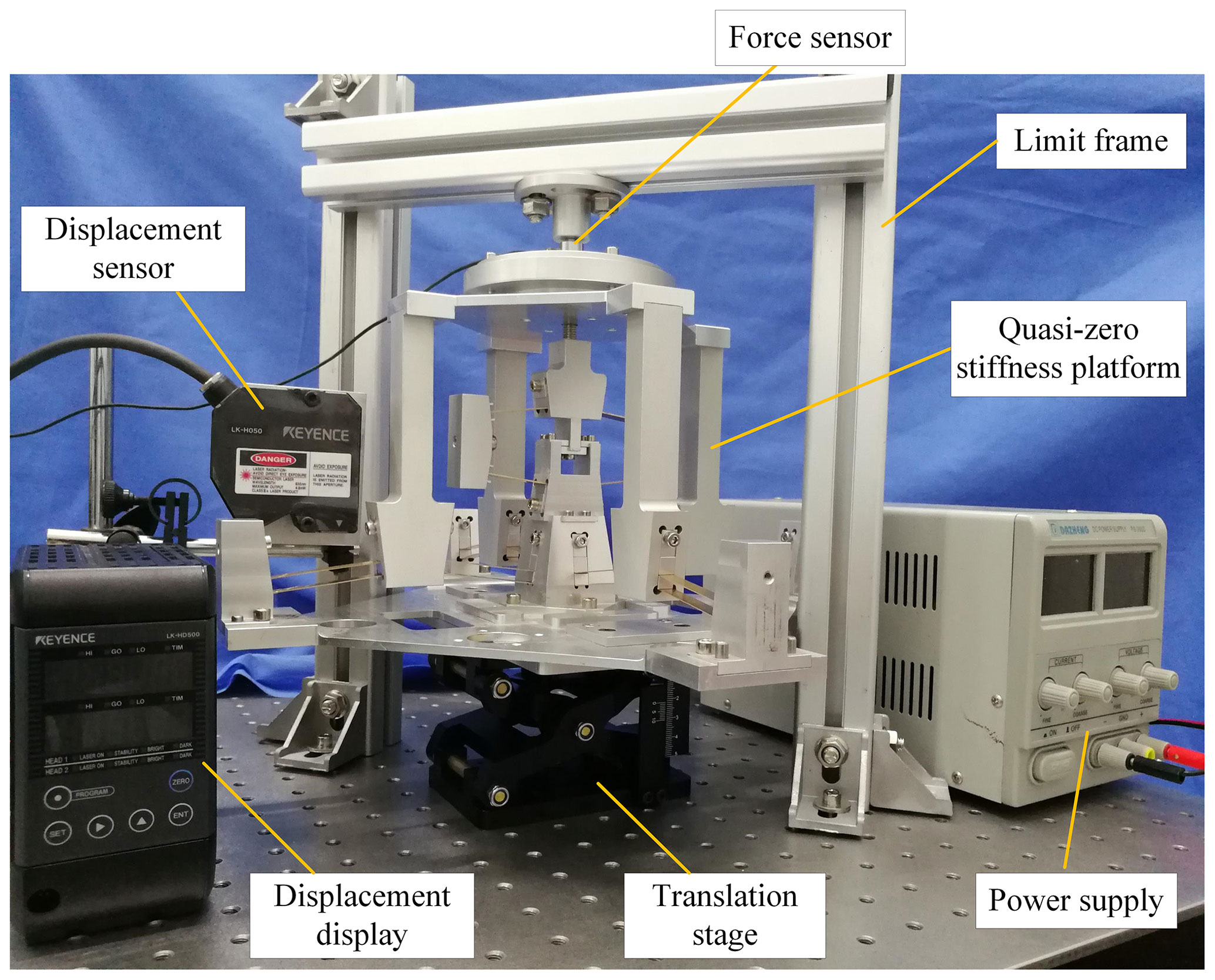
The setup of the first test is shown in Fig. 16. In the first force–displacement test, displacement was applied to the quasi-zero stiffness platform by an actuating translation stage. The driving displacement of the platform is measured with a laser displacement sensor (model: LK-G5000, from Keyence Corp., Osaka, Japan). The output force of the platform is measured by a force sensor (model: T301, from Changzhou Right Measurement & Control System Co., Ltd., Changzhou, China). Using the raw data acquired from position and force sensor, the force–displacement behavior of the prototype platform is obtained, as shown in Fig. 17. For accurate comparison between experiment and theoretical results, the analytical force–displacement curve is also depicted in Fig. 17.
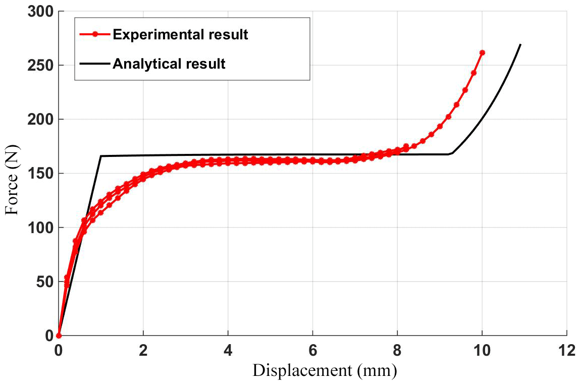
From the Fig. 17, it is obvious that in the zero-stiffness range, the force-displacement curve is close to horizontal and rises slightly slowly, which means quasi-zero stiffness and constant-force property of the prototype platform. The experimental results show that the constant force is 160 N, which very closely marches the analytical result of 168 N with a discrepancy of 4.7 %. However, the force-displacement curve is not completely horizontal and rises slightly slowly. The reason is that the buckling of each fixed-guided beam is not completely the same. Some fixed-guided beams buckle more than others due to errors in assembly and manufacturing of beam members and the slight discrepancy of the constant force output is also caused by the assembling and manufacturing error of the mechanism. Although there are some inconsistencies, the error between the theoretical and the experimental results is within an acceptable range.
5.3 Test 2: vibration isolation experiment of the prototype
The setup of the second test is shown in Fig. 18. In the second test, we will verify the vibration isolation performance of the quasi-zero stiffness mechanism used as vibration isolator. Vibration was exerted to the base of the vibration isolator by a voice coil motor (model: VCAR0113-0089-00A, from Suzhou Unite Precision Technology Co., Ltd., Suzhou, China). The VCM will generate a series of vibration outputs with frequency from 2 to 5 Hz and amplitude of 2 mm. Subsequently, vibration of moving platform was measured with the laser displacement sensor (model: LK-G5000, from Keyence Corp., Osaka, Japan) in the way that the displacement was measured in Test 1.
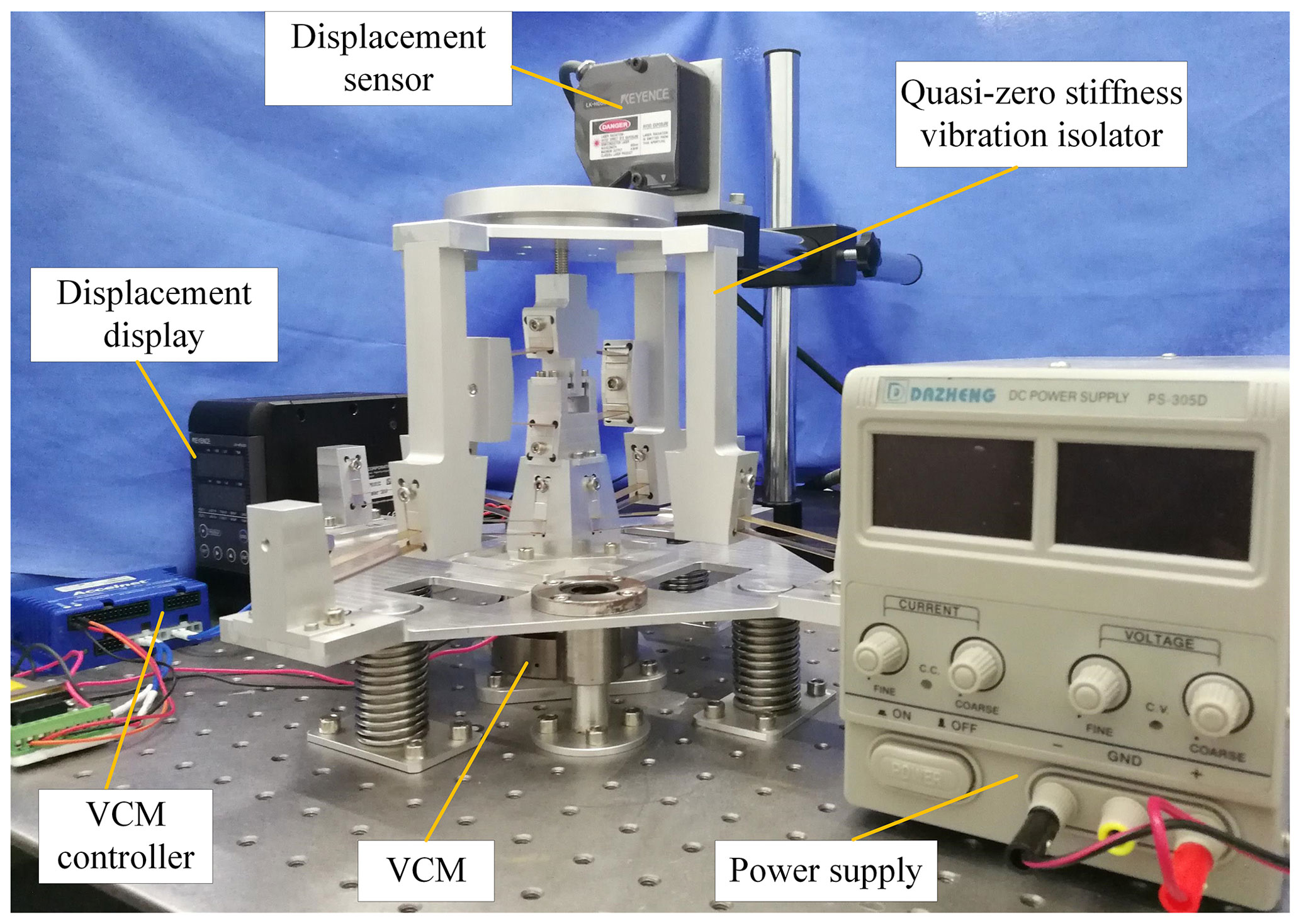
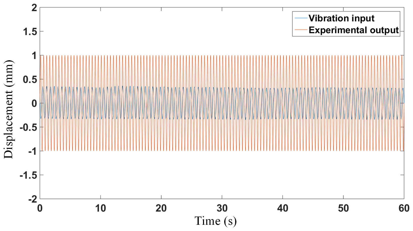
Figure 19 shows the output of an experimental conducted at a vibration frequency of 2 Hz and amplitude of 2 mm. The load of the mechanism reaches 50N, and then the load capacity of the mechanism is adjusted to match it. The experimental results show that the vibration attenuation is about 65 %. In theory, the vibration attenuation of the quasi-zero stiffness mechanism should be 100 %. However, due to assembly and manufacturing errors, the mechanism does not achieve quasi-zero stiffness completely, so the vibration isolation effect is affected. The closer the zero-stiffness curve of the mechanism is to horizontal and linear, the better the vibration isolation effect will be. Overall, although not as perfect as the theoretical vibration isolation effect, the isolation performance is still satisfactory.
In the future work, the application of mechanism in vibration isolation will be further explored and the influence of the exciting frequency on the transmissibility ratio and the isolation region will be investigated in more detail. In the processing of the mechanism, the manufacturing precision should be improved, and the assembly error should be reduced, so that the beams of the mechanism are bent to the same extent. In addition, based on the existing one-dimensional quasi-zero stiffness mechanism, a new bistable mechanism and a new multi-dimensional zero stiffness mechanism will be designed.
A novel bistable linear negative-stiffness mechanism with large in-plane lateral stiffness are first developed in this paper, and then, based on this, a novel quasi-zero stiffness mechanism is proposed by connecting the novel negative-stiffness compliant mechanism in parallel with positive-stiffness mechanism. Both the negative-stiffness mechanism and the quasi-zero stiffness mechanism have good axial guidance capability and in-plane lateral anti-interference capability. At the same time, the proposed quasi-zero stiffness mechanism has extremely low and even zero dynamic stiffness, while it still keeps a high loading capacity, that is, it has a High-Static-Low-Dynamic-Stiffness characteristic. Analytical modeling of bistable mechanism based on a comprehensive elliptic integral solution is derived and the stiffness curve of both traditional and novel bistable mechanism is analyzed. The quasi-zero stiffness mechanism can be used as constant-force mechanism and passive vibration isolation mechanism due to its quasi-zero stiffness characteristic. A prototype of the quasi-zero stiffness mechanism with adjustable constant force output or load-carrying capacity has been designed in detail and fabricated to demonstrate the performance of the proposed design. Experimental results show that the force-displacement curve is close to horizontal and rises slightly slowly, which indicates quasi-zero stiffness and constant-force property. In addition, the isolation performance is satisfactory despite the slight discrepancy between theoretical and experimental results. The slight discrepancy is caused by the assembling and manufacturing error of the platform.
The data that support the findings of this study are available from the corresponding author, Wei Dong, upon reasonable request.
ZZ conceived and designed the study. ZZ and YG performed the experiments. ZZ wrote the paper. LS, WD and ZD reviewed and edited the manuscript. All authors read and approved the manuscript.
The authors declare that they have no conflict of interest.
This research has been supported by National Key Research and Development Plan (grant no. 2017YFB1303101).
This paper was edited by Anders Eriksson and reviewed by two anonymous referees.
Carrella, A., Brennan, M. J., and Waters, T. P.: Static analysis of a passive vibration isolator with quasi-zero-stiffness characteristic, J. Sound. Vib., 301.3–5, 678–689, 2007.
Carrella, A., Brennan, M. J., Waters, T. P., and Shin, K.: On the design of a high-static–low-dynamic stiffness isolator using linear mechanical springs and magnets, J. Sound. Vib., 315.3, 712–720, 2008.
Chase Jr., R. P., Todd, R. H., Howell, L. L., and Magleby, S. P.: A 3-D Chain Algorithm with Pseudo-Rigid-Body Model Elements, Mech. Based Des. Struc., 39.1, 142–156, 2011.
Coulter, B. A. and Miller, R. E.: Numerical Analysis of a Generalized Plane Elastica With Non-Linear Material Behavior, Int. J. Numer. Meth. Eng., 26, 617–630, 1988.
Dong, G., Zhang, X., Xie, S., Yan, B., and Luo, Y.: Simulated and experimental studies on a high-static-low-dynamic stiffness isolator using magnetic negative stiffness spring, Mech. Syst. Signal. Pr., 86, 188–203, 2017.
Dong, G., Zhang, X., Luo, Y., Zhang, Y., and Xie, S.: Analytical study of the low frequency multi-direction isolator with high-static-low-dynamic stiffness struts and spatial pendulum, Mech. Syst. Signal. Pr., 110, 521–539, 2018.
Dunning, A. G., Tolou, N., and Herder, J. L.: A compact low-stiffness six degrees of freedom compliant precision stage, Precis. Eng., 37.2, 380–388, 2013.
Hao, G., Mullins, J., and Cronin, K.: Simplified modelling and development of a bi-directionally adjustable constant-force compliant gripper, P. I. Mech. Eng.-C J. Mec., 231.11, 2110-2123, 2017.
Holst, G. L., Teichert, G. H., and Jensen, B. D.: Modeling and Experiments of Buckling Modes and Deflection of Fixed-Guided Beams in Compliant Mechanisms, J. Mech. Design., 133.5, 051002, https://doi.org/10.1115/1.4003922, 2011.
Howell, L. L.: Compliant mechanisms, John Wiley & Sons, https://doi.org/10.1007/978-1-4471-4510-3_7, 2001.
Huang, X., Liu, X., Sun, J., Zhang, Z., and Hua, H.: Vibration isolation characteristics of a nonlinear isolator using Euler buckled beam as negative stiffness corrector: A theoretical and experimental study, J. Sound. Vib., 333.4, 1132–1148, 2014.
Ibrahim, R. A.: Recent advances in nonlinear passive vibration isolators, J. Sound. Vib., 314.3–5, 371–452, 2008.
Jensen, B. D. and Howell, L. L.: Identification of Compliant Pseudo Rigid-Body Four-Link Mechanism Configurations Resulting in Bistable Behavior, ASME J. Mech. Des., 125, 701–708, 2003.
Kashdan, L., Conner Seepersad, C., Haberman, M., and Wilson, P. S.: Design, fabrication, and evaluation of negative stiffness elements using SLS, Rapid Prototyping J., 18.3, 194–200, 2012.
Kim, C. and Ebenstein, D.: Curve Decomposition for Large Deflection Analysis of Fixed-Guided Beams with Application to Statically Balanced Compliant Mechanisms, J. Mech. Robot., 4.4, 0410094, https://doi.org/10.1115/1.4007488, 2012.
Kovacic, I., Brennan, M. J., and Waters, T. P.: A study of a nonlinear vibration isolator with a quasi-zero stiffness characteristic, J. Sound. Vib., 315.3, 700–711, 2008a.
Kovacic, I., Brennan, M. J., and Lineton, B.: On the resonance response of an asymmetric Duffing oscillator, Int. J. Nonlin. Mech., 43.9, 858–867, 2008b.
Liu, X., Huang, X., and Hua, H.: On the characteristics of a quasi-zero stiffness isolator using Euler buckled beam as negative stiffness corrector, J. Sound. Vib., 332.14, 3359–3376, 2013.
Ma, F. and Chen, G.: Modeling large planar deflections of flexible beams in compliant mechanisms using chained beam-constraint-model, J. Mech. Robot., 8.2, 021018, https://doi.org/10.1115/1.4031028, 2016.
Masters, N. D. and Howell, L. L.: A Self-Retracting Fully Compliant Bistable Micromechanism, J. Microelectromech. S., 12, 273–280, 2003.
Platus, D. L.: Negative-stiffness-mechanism vibration isolation systems, P. Soc. Photo-Opt. Ins., 3786, 98–105, 1999.
Ren, C., Yang, D., and Qin, H.: Mechanical Performance of Multidirectional Buckling-Based Negative Stiffness Metamaterials: An Analytical and Numerical Study, Materials, 11.7, 1078, https://doi.org/10.3390/ma11071078, 2018.
Wang, P. and Xu, Q.: Design of a compact compliant constant-force XY precision positioning stage, 2016 12th IEEE/ASME International Conference on Mechatronic and Embedded Systems and Applications (MESA), IEEE, 29 August 2016, Auckland, New Zealand https://doi.org/10.1109/MESA.2016.7587107, 2016.
Wang, P. and Xu, Q.: Design of a flexure-based constant-force XY precision positioning stage, Mech. Mach. Theory, 108, 1–13, 2017.
Xu, Q.: New Flexure Parallel-Kinematic Micropositioning System with Large Workspace, IEEE T. Robot., 28.2, 478–491, 2012.
Xu, Q.: Design of a Large-Stroke Bistable Mechanism for the Application in Constant-Force Micropositioning Stage, J. Mech. Robot., 9, 011006, https://doi.org/10.1115/1.4035220, 2017a.
Xu, Q.: Design of a Constant-Force Microgripper Mechanism for Biological Micromanipulation, 2017 IEEE 12th International Conference on Nano/Micro Engineered and Molecular Systems (NEMS), IEEE, 9 April 2017, Los Angeles, USA California, USA, 418–421, https://doi.org/10.1109/NEMS.2017.8017055, 2017b.
Zhang, A. and Chen, G.: A Comprehensive Elliptic Integral Solution to the Large Deflection Problems of Thin Beams in Compliant Mechanisms, J. Mech. Robot., 5.2, 021006, https://doi.org/10.1115/1.4023558, 2013.
Zheng, Y., Li, Q., Yan, B., Luo, Y., and Zhang, X.: A Stewart isolator with high-static-low-dynamic stiffness struts based on negative stiffness magnetic springs, J. Sound. Vib., 422, 390–408, 2018.
Zhou, N. and Liu K.: A tunable high-static-low-dynamic stiffness vibration isolator, J. Sound. Vib., 329.9, 1254–1273, 2010.
- Abstract
- Introduction
- Modeling and analysis of conventional bistable compliant mechanisms
- Design of novel bistable compliant mechanism
- Design of quasi-zero stiffness compliant mechanism
- Experimental validation
- Conclusion
- Data availability
- Author contributions
- Competing interests
- Financial support
- Review statement
- References