the Creative Commons Attribution 4.0 License.
the Creative Commons Attribution 4.0 License.
 | 19 Feb 2019
Dynamic Reliability Analysis of Rotary Steering Drilling System
Leilei Huang
Baolin Liu
Chunxu Yang
Ruihe Wang
Laiju Han
Vibration and high shock are major factors in the failure of downhole tools. It is important to study the causes of vibration and shock formation to prevent failure of the drillstring and bottom hole assembly (BHA). At present, it is generally recognized that the vibration of drillstring is the main reason for the failure, especially the lateral vibration. In this paper, the bottom tool of Rotary Steering Drilling System (RSS) calculation model was established based on the secondary development of ABAQUS software. Starting from the initial configuration of drilling tool, considering the contact impact of drilling tool and borehole wall, the dynamic excitation of guide mechanism and the drilling pressure, torque, rotational speed, gravity, buoyancy, drilling fluid damping. The dynamic characteristics of the inherent frequency and dynamic stress of the bottom hole assembly (BHA) were calculated and analyzed, and risk assessment method based on the quantitative vibration intensity was established. The reliability of typical drilling tool is evaluated, which provides a reference for the optimization design of BHA of Rotary Steering Drilling System.
- Article
(4136 KB) -
Supplement
(138 KB) - BibTeX
- EndNote


Drillstring and downhole tool failure usually results from failing to control one or more of the vibration mechanisms. The drillstring motion state is affected by several factors and interaction among them, like drilling load, drillstring itself, drilling fluid, well wall and bottom rock (Wang et al., 2015). The vibration of the drillstring can be divided into three primary modes: axial, lateral (also referred to as transverse, or bending), and torsional modes, with different destructive natures (Ritto et al., 2013; Liao et al., 2012). In the axial mode, the vibration is a longitudinal movement along the drillstring. In the transverse mode, the vibration is a lateral movement that causes bending or bending of the component, resulting in a stress reversal in which one side is in a different tension state than the other side. In the torsional mode, the vibration is resistance to the rotation resulting in twisting as torque is applied to overcome resistance (Nave and Dvorkin, 2015; Ghasemloonia et al., 2014; Ritto et al., 2013).
Wilson and Heisig (2015) found that lateral vibration is more severe than vertical vibration, because the bending stress is high while vertical stress caused by axial vibration is not severe. Lateral vibration is very easy to happen in side tracking, and the lowest resonant frequency depends on properties of drillstring material and drilling fluid. Qu (1995) discussed lateral vibration under the effect of drilling fluid inside and outside by using solid-liquid coupling vibration theory, he concludes that drilling fluid can be equivalent to generalized distributive mass, and the effect of drilling fluid cannot be neglected. Shor et al. (2015) utilizing finite element method get conclusion that mass unbalance has a great influence on lateral vibration, and when the drillstring vibrates at the inherent frequency, the friction between the drillstring and well wall becomes more severe. Drillstring dynamics study are mainly by method of theoretical computation due to the difficulty of experiments. Millheim et al. (1978) lay the foundation of using finite element in dynamics analysis. The finite element computer program to analyze the behavior of bottom-hole assemblies of drill collars, stabilizers and drill bit is discussed. Wilson and Heisig (2015), Schmalhorst and Neubert (2003), Jogi et al. (2002) and Yigit et al. (1996) utilized both differential equation solution and finite element method to analysis the drillstring dynamics, and some of their work has formed commercial software. In most cases analytical models are used to get a fast overview of natural axial and torsional frequencies of drillstrings in straight boreholes. To develop practical and commercial computing software about drillstring dynamics, the model established must take lithology, bit type, drill assembly, damping and contact into consideration, meanwhile through a lot of experiments and experiment data analysis, comparison with theoretical computing results, various parameters or boundary conditions in theoretical calculation can be corrected. Therefore, it takes a lot of hard work to develop software for drillstring dynamics. Based on this situation, secondary development based on commercial finite element software is one feasible technical approach, which reduces large amount of work for calculation method and program verification.
Several studies have been devoted to better understand the full dynamics of the rotary drilling systems (Yigit and Christoforou, 1996, 1998; Khulief and Al-Naser, 2005; Sampaio et al., 2007; Kapitaniak et al., 2015). Gupta and Wahi (2016) developed a global dynamic of the coupled axial-torsional vibrations incorporating the possibility of bit-bounce. Huang et al. (2015) established a generalized quasi-static model of drillstring system, the forward model and inversion model are further combined into a unity. Lian et al. (2015) established a nonlinear dynamics model to investigate the motion behavior of drillstring in gas drilling of horizontal wells, a finite element model was also established and the buckling and contact of drillstring was analyzed. However, none of these studies have reported the dynamical motion state of the bottom hole assembly (BHA) in Rotary Steerable Drilling System (RSS) (Jones et al., 2016), the whole drillstring is rotated from the surface by a hydraulically driven top drive. The RSS has push-the-bit tools (Warren, 1998) which using pads on the outside of the tool which press against the well bore thereby causing the bit to press on the opposite side causing a direction change. The pads of the implementing agencies in RSS constantly pushed against the borehole wall, making bottom hole by a cycle of nonlinear damping force, which is lead to the bottom drilling tool movement of chaos and disorder (Wang et al., 2014; Xue et al., 2015, 2019).
Statistics study (Lin et al., 2016) shows that drillstring failure and cross-over sub failure account for approximately 54 % of drilling tool failures. Among the drillstring thread fracture incidents, 70 % of them occurred at box thread and 30 % occurred at pin thread. The causes for drillstring failure encountered during drilling practice have been systematically analyzed based on the statistical data (Wang et al., 2011; Abdo, 2006; Abdo and Abouelsoud, 2011). Fault tree of drillstring failure has been subsequently constructed (Wang et al., 2011).
In this paper, the bottom tool of RSS calculation model was established based on the secondary development of ABAQUS software. Starting from the initial configuration of drilling tool, considering the contact impact of drilling tool and borehole wall, the dynamic excitation of guide mechanism and the drilling pressure, torque, rotational speed, gravity, buoyancy, drilling fluid damping. The dynamic characteristics of the inherent frequency and dynamic stress of the BHA were calculated and analyzed, and risk assessment method based on the quantitative vibration intensity was established. The reliability of typical drilling tool is evaluated, which provides a reference for the optimization design of drilling tools.
Drillstring actual working condition is very complex, and it's hard to simulate and analyze the actual working condition precisely. Due to the complexity of the drilling operation, the mathematical calculation model cannot effectively explain the fatigue failure of the drillstring caused by the cyclic stress due to vibration and high shock. Since the dynamics of the drillstring involve wide vibration profiles including axial, lateral and torsional modes, the mathematical modeling of such long rotating components is highly nonlinearity.
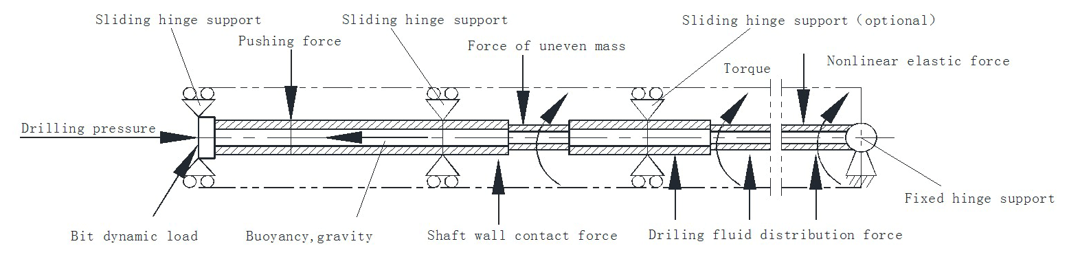
Therefore, secondary development based on commercial finite element software is a feasible technical solution. In this paper, the drillstring be simplified by basic assumptions when establish a vibration analysis model in ABAQUS software. The BHA calculation model of the RSS is shown in Fig. 1, making the following assumptions in the calculation process of the entire dynamic system.
-
The borehole section is circular and the well wall is rigid;
-
The axis of drillstring is at the same line with well axis before drillstring moves, and the drillstring node has three-dimensional freedom;
-
The bottom drillstring is considered as a beam, whose one end is hinging support and the other end is movable hinge support. The drill bit and the stabilizer are movable hinge support, push contact is one-way movable support;
-
The drillstring is considered as homogeneous, small deformation and elastic beam, the joint is neglected, and drillstring displacement is restrained by wellbore;
-
The drilling fluid influence on drillstring vibration characteristics is considered.
Dynamic equilibrium equation of drilling dynamics system can be expressed as:
wherein U is generalized displacement, is generalized velocity, is generalized acceleration, P is external force, M is mass matrix, K is stiffness matrix, C is damping matrix.
Considering that the inside of the drill is filled with liquid and the outer annulus also has drilling fluid, the unit of drillstring could have the ability to withstand greater stress and deflection. The stiffness matrix of the unit is shown in Eq. (2) (the equation details can be found in the Supplement).
wherein, A is cross-sectional area, E is Young's modulus, L is unit length, G is shear modulus, J is torsional moment of inertia, if Ix=0, then define Jx, if Ix≠0, then define Ii, where Ix is input torsional moment of inertia about the x axis, Iy is moment of inertia about y axis, Iz is moment of inertia about z axis; is polar moment of inertia. Then we can define , , , , …, , , the following equations can be obtained.
wherein Ii is the normal moment of inertia in the i direction, is the shear area perpendicular to the direction i, where , is the shear coefficient. Then we can get the torque TT as following:
wherein, the standard option for torque is 0, and the twisted pair for torque imbalance is ; GT is the twisted pair tensile stiffness constant; Di is the in-tube diameter, its value is equal to Do−2tw; tw is the wall thickness, mm; Do is the outer diameter, mm.
The mass matrix of the unit is shown in Eq. (10) (the equation details can be found in the Supplement), and its mass matrix is similar to the mass matrix of ordinary beam elements. Only some elements need to be revised, multiplied by the coefficient Ma∕Mt.
wherein,
wherein, mw is the mass of the drillstring per unit length; mint is the mass of the internal fluid per unit length; mins is the quality of the external additional layer, set mins=0; madd is the additional mass of external fluid; ρ is the density of drillstring; CM is the additional mass factor for external fluid; ρf is fluid density.
Then we can define , , , … , , radius of rotation , and . Detailed calculation expression is as follows:
The natural frequency (Jogi et al., 2002) can be obtained by analyzing the dynamic response of the structure when the external load is zero (in the dynamic equilibrium equation P=0). In Abaqus software, the vibration mode is calculated for the undamped system. In this case, the equation of motion can be expressed as:
wherein ω is the natural frequency of the drillstring system.
The n-order natural frequency and the n-order natural mode of the drillstring can be obtained by the Eq. (21), and calculation of the natural frequency and the natural mode is mathematically a problem of calculate all the eigenvalues of the matrix. For the vibration damage caused by the general engineering structure, it usually only occurs in the lower frequency range, so only a few lower order natural frequencies will be obtained.
However, most engineering problems still involve damping, although the damping may be small. The relationship of natural frequency between the damped and the undamped is:
wherein, ωd is the natural frequency of the system when damping, ξ is the damping ratio.
Based on the above analysis and Hamilton's principle, the dynamic model of the drillstring system can be derived as follows:
Where, u is node displacement or rotation, rad; M is the mass matrix; FF is drilling fluid distributive force, kN m−1; Fw is well bore contact force, kN; FG is nonlinear elastic force, kN; R is static force (gravity, buoyancy, WOB, etc.), kN; FE is exciting force (uneven quality force, axial bit load, lateral bit load), kN. The load form and load condition need to be selected and specialized. Due to working characteristics of RSS, all external forces, such as push force, well wall contact force, drilling fluid distributive force, nonlinear elastic force, are taken into consideration besides bit load, gravity and buoyancy.
3.1 Risk assessment method based on quantitative vibration intensity
The drillstring failure and cross-over sub failure account for approximately 54 % of drilling tool failures. Drillstring and downhole tool failure usually results from failing to control one or more of the vibration mechanisms. We established a risk assessment method based on quantitative vibration intensity, the evaluation process is shown in Fig. 2.
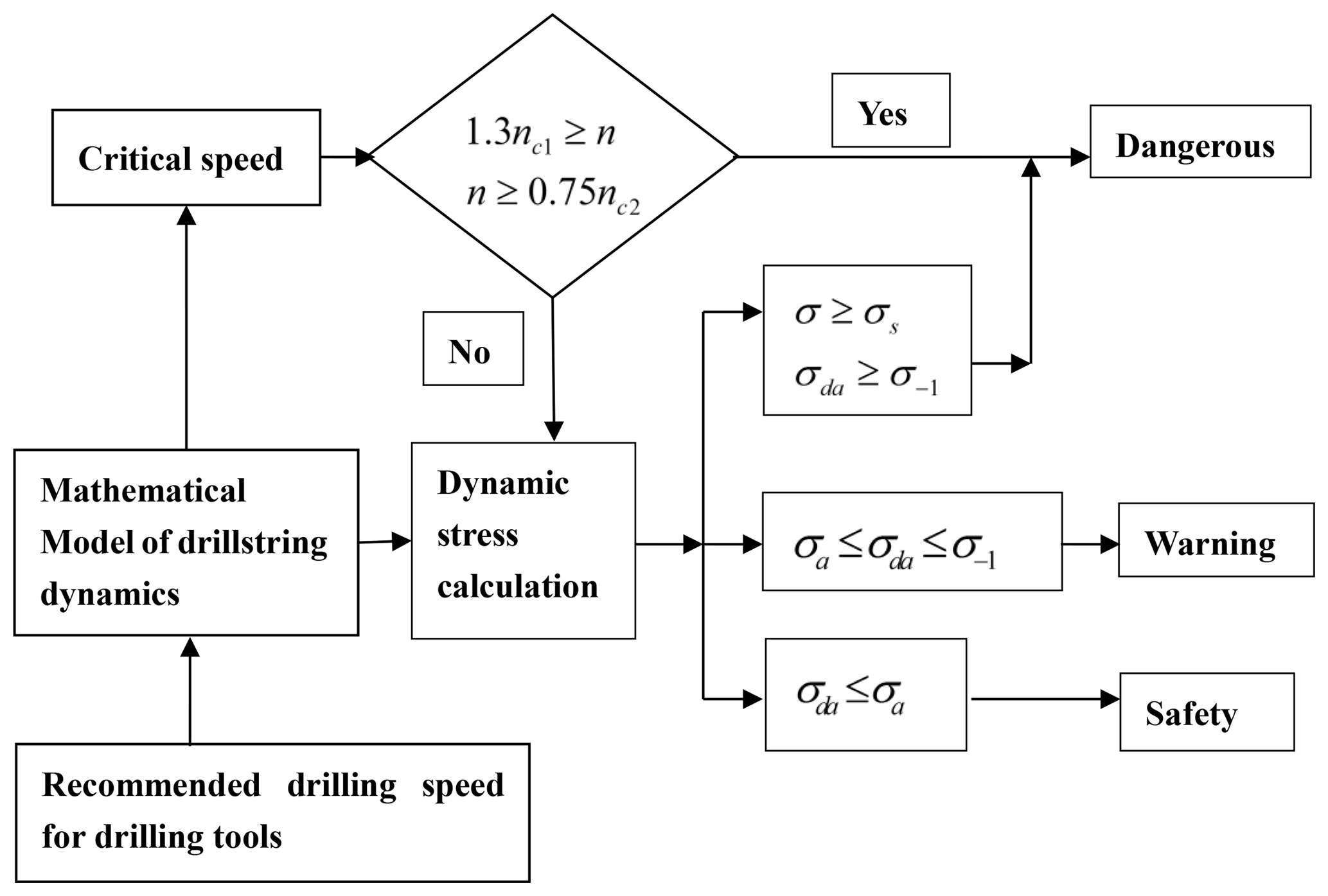
As show in Fig. 2, according to the initial designed speed and drilling tool combination, the calculation model is established. Firstly, the critical speed is calculated, and the range of relevant frequencies is taken to determine the danger control point. The drilling tool is not allowed to be attached to the critical speed. For a specific speed, it may be between the two critical speeds, the low critical speeds are expressed as nc1, and the high critical speeds are expressed as nc2, if the design speed is satisfied , no resonance will occur and the point control requirements will be satisfied. If the above conditions are not satisfied, the recommended speed value is given as the intermediate value of the two-stage critical speed, that is .
From the calculation results above, the length of drillstring is large, the natural frequency is small, and sometimes the recommended value is difficult to stay away from the resonance speed. Of course, because of the existence of the wellbore, even if the drillstring speed is close to the critical speed, there will be no infinite amplitude, but the collision between the drillstring and the wellbore will be intensified. When the rotating speed is close to the natural frequency, under the action of periodic excitation load, the drillstring is usually in some violent vibration state, and the drillstring has a certain dynamic stress level. Further stress level judgment is needed to determine the reliability of the recommended speed.
The mechanical properties of the drillstring need to be determined when determine stress intensity, that include the tensile strength σb, yield limit σs, symmetrical cyclic fatigue limit σ−1 and allowable stress amplitude σa which considering the effects of mean stress. According to the dynamic model, the vibration stress will be obtained, and the time series of the equivalent stress will be obtained, so the transient stress σ, the equivalent stress amplitude σda and the equivalent average stress σdn can be obtained. And by contrasting allowable stress amplitude σa, the fatigue limit σ−1, and yield limit σs, the condition is defined as “safety” when equivalent stress amplitude σda is low, less than the revised allowable fatigue stress amplitude σa; The condition is defined as “warning” when equivalent stress amplitude σda exceeds revised allowable fatigue stress amplitude σa, but less than the fatigue limit σ−1, and should be handled carefully, it is not allowed to occur that the equivalent stress amplitude exceeds the fatigue limit σ−1 or the instantaneous stress σ exceeds the yield strength σs. Therefore, it is necessary for the construction personnel to make quick treatment and control the vibration intensity.
3.2 Calculation method and judgment principle
3.2.1 Calculation of equivalent stress amplitude and equivalent average stress
When the fatigue strength check with known three-way stress, the multi-direction stress is often converted into equivalent stress in engineering, and then the fatigue check is carried out according to the stress state. According to a large number of experiments, the deformation energy intensity theory combines the multidirectional stress state with the unidirectional stress state, which is more in line with the practical theory. According to the deformation energy intensity theory, the multidirectional stress will transform into a unidirectional force.
Then the equivalent stress amplitude σda can be defined:
The equivalent mean stress σdm will be defined as:
wherein σa1, σa2 and σa3 are the main stress amplitude, MPa; σm1, σm2 and σm3 are the average magnitude of principal stress, MPa.
If the time series of equivalent stress is obtained by measurement, its equivalent stress σda amplitude and equivalent average stress σdn can be obtained.
where equivalent stress amplitude expressed as:
Equivalent mean stress expressed as:
3.2.2 Calculation of mechanical performance parameters
To simplified the calculation model, combined with the fatigue endurance limit test of drillstring, the approximate calculation formula of the cycle endurance limit of drillstring under the condition of underground corrosion was adopted. The fatigue limit σ−1 under symmetrical circulation is shown in Eq. (28).
wherein σs is the yield strength, MPa, σb is tensile limit, MPa.
The fatigue allowable stress amplitude formula for under symmetrical circulation expressed as:
wherein, σ−1 is the allowable stress amplitude, MPa; β is surface mass coefficient; Kσ is effective stress concentration factor; εσ is size coefficient; σ−1 is fatigue limit under symmetric circulation, MPa; S is the safety factor. According to the actual situation of drillstring, we set Kσ=1, εσ=0.74, β=0.9, S=2.
It is necessary to modify the allowable fatigue stress value when considering the effect of average stress according to the previous calculation. Goodman line is often used for modification in engineering, which is relatively simple and the calculation results tend to be safe, so it is widely used (Budynas and Nisbett, 2014). The Goodman's line calculation formula can be expressed as:
wherein, σa is allowable stress amplitude considering the effects of mean stress, σD is the allowable stress amplitude under symmetrical circulation, equal to σ−1, MPa; σm is equivalent mean stress, MPa; σb is tensile strength, MPa.
3.2.3 Principle of judgment
The judgment principle of vibration stress intensity is defined in this paper as following:
-
σda≤σa, drillstring vibration intensity is small, can be identified as safely.
-
, the vibration intensity of drillstring is large, can be identified as warning.
-
σ≥σs or , the vibration intensity of drillstring is too high, can be identified as dangerous.
3.3 Secondary development software
In this paper, we established calculation program of the RSS based on the secondary development of Abaqus software. The modeling starts from the drill bit, input the length, outer diameter and inner diameter of each section in sequence according to the different cross-sections of drilling tool combination. In the column of material properties, the elastic modulus, Poisson's ratio, and density of materials are respectively input, where the unit of elastic modulus is MPa and the unit of density is t mm−3.
Load column input weight on bit, rotary torque, slap backup force and impact force, according to the actual situation input weight on bit, rotary table torque, slap pushing and collision force, the naming principles of section number is the number under push position. At the same time input the drillstring rotary speed in the working process, the unit is r min−1, and then meshing, at last in the task volume input file name and the number of CPU, and then click OK, begin to automatically calculate the dynamic stress of drillstring assembly. In the column of material mechanics parameters, input material yield strength and tensile strength, in the column of calculation results, input maximum instantaneous stress, the maximum and the minimum fluctuation stress, and then click OK, appear evaluation results of assembly dynamic stress.
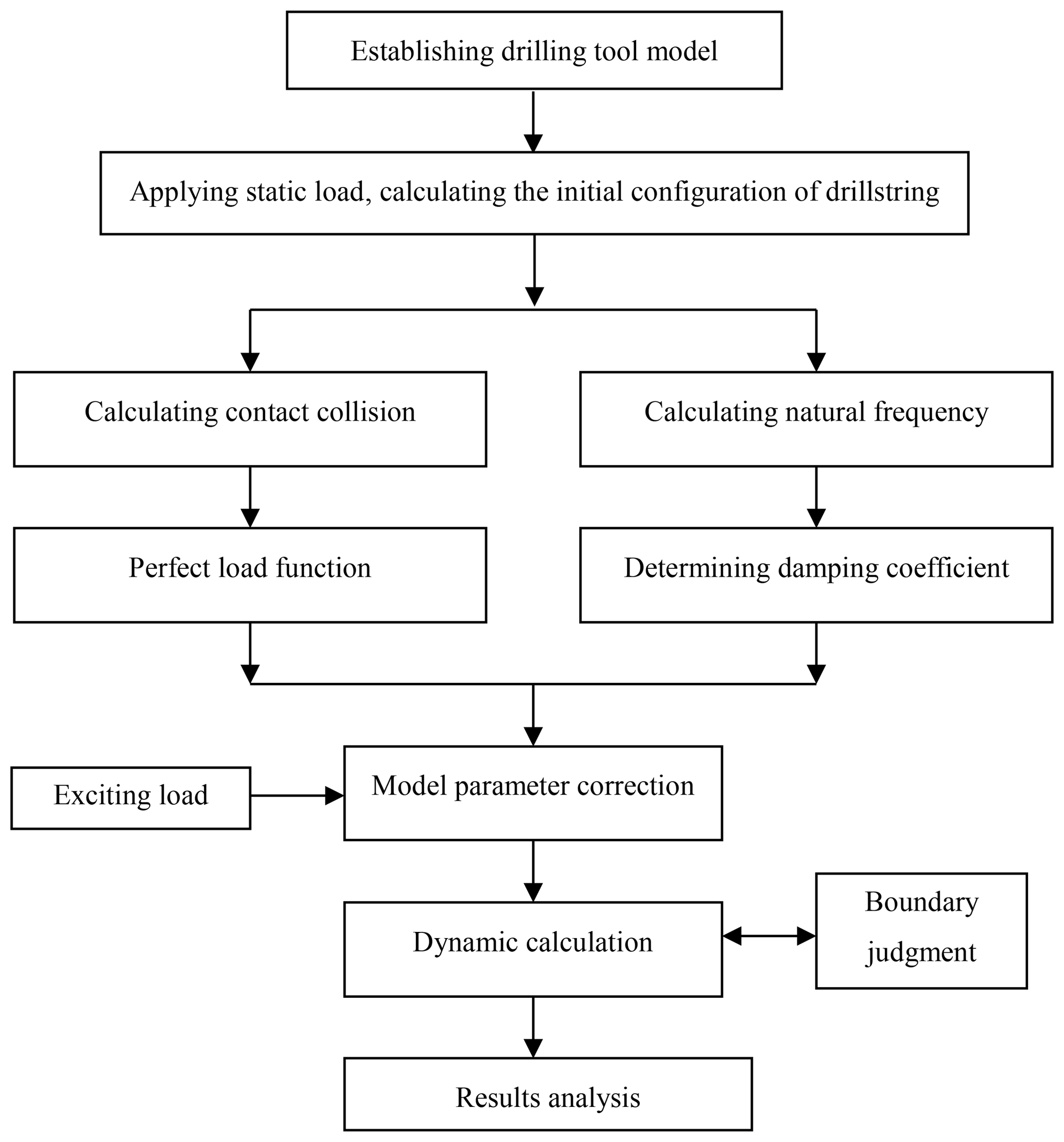
Calculation process in the software is shown as in Fig. 3. Firstly, by using Abaqus model input, establish drillstring dynamics model, set analysis steps, define contact and impose static load, and simulate quasi-static deformation process of the contract model between drillstring and wellbore which is under axial pressure, and obtain drillstring initial configuration. Analyze the buckling results, the initial displacement is obtained and the deformation model is imported for further dynamic analysis. On the one hand, the collision calculation is carried out to obtain the collision contact force function. On the other hand, the natural frequency of the model is calculated to determine the damping coefficient of the system. The calculated collision contact force function and damping coefficient are introduced into the model, and other load functions such as speed, torque, gravity, buoyancy and pushing force are applied. Submit the work for dynamic calculation. During the calculation, the boundary changes are monitored in real time, and the boundary corrections are made in case of collision. The time history of dynamic stress under various excitation loads and the deformation, velocity and acceleration of drillstring are obtained.
4.1 Initial conditions for calculation
BHA design parameters: Drill bit (φ215.9 mm), rotary steerable tool (φ197 mm), drillstring (φ127 mm), undersized centralizer (φ210 mm), flexible sub (φ172 mm), drill collar (φ172 mm, length 6 m), non-magnetic drill pipe (φ127).
The elastic modulus of drill assembly is 206 GPa, Poisson's ratio is 0.3, drillstring material density is 7850 kg m−3, and drilling fluid density is 1150 kg m−3. Well bore diameter is 216 mm. The rotary table torque applied to the drillstring is 10 kN m, weight on bit is 80 kN, and excitation load is applied to the pushing block. The whole drillstring is affected by gravity, buoyancy and damping force of drilling fluid.
When different angular velocity is applied to the drillstring, the corresponding period will be changed. The drill assembly has one end hinge branch, the other end movable hinge, the centralizer movable hinge, the shaft wall solid branch.
4.2 Dynamic Stress Calculation
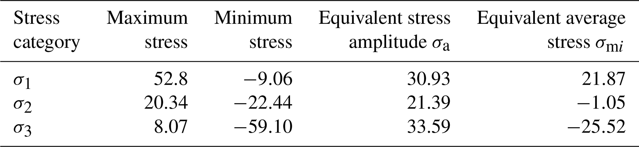
The principal stresses in three directions are shown in Fig. 4. The principal stress time series curve satisfies the condition of periodic cycle, but there is error in symmetry.
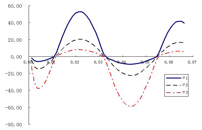
For the first principal stress, the maximum stress (MPa), and the minimum stress (MPa), so the main stress amplitude will be calculated as follows.
The average stress in the direction of the principal stress amplitude can be calculated:
Similarly, the same formula is used to calculate the second and third principal stress, as shown in Table 1. The equivalent stress amplitude σda is calculated:
equivalent mean stress calculated:
Relative to drillstring materials, σb=827 (MPa), σs=758 (MPa), other coefficients are selected in accordance with Sect. 4.1. We can obtain,
wherein, σs is yield strength, MPa; σb is tensile strength, MPa.
Then the allowable stress under symmetric circulation is,
According to the above calculation data, the allowable stress amplitude σa considering the influence of average stress is,
Then, σ is obviously less than σs, and σda<σa, therefore, meets the fatigue strength requirement.
4.3 Natural vibration characteristic
Firstly, the model of drillstring combination is established. Apply boundary conditions to the model, drillstring has one end hinge branch, the other end movable hinge, the centralizer movable hinge. Take the previous order eigenvalues, the natural frequency of the BHA will be obtained as shown in Table 2.
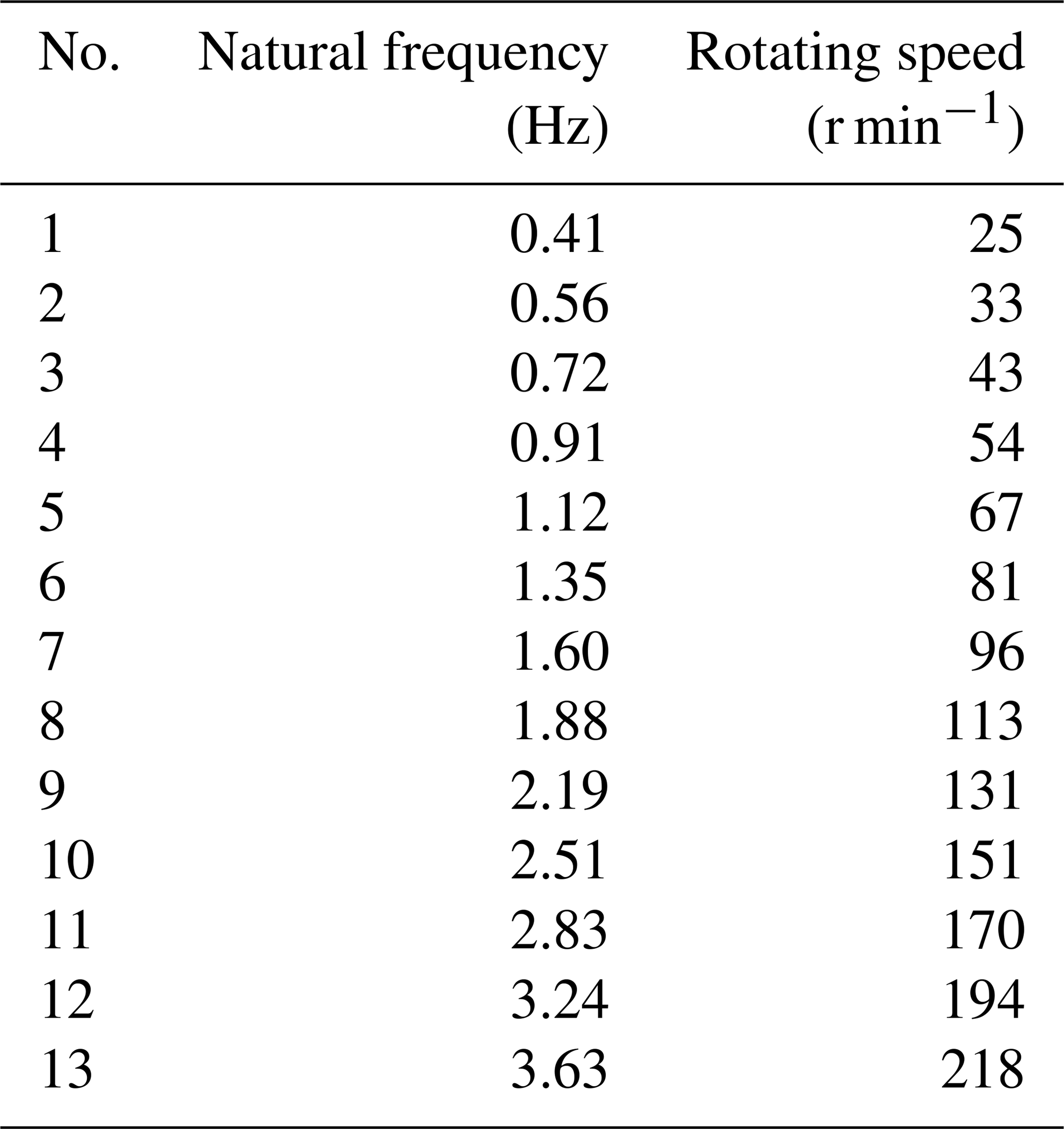
As shown in Table 2, for a drillstring with a large length, the natural frequency or critical speed is relatively dense, and it is difficult to completely avoid the critical speed. At this time, it is necessary to avoid the critical speed as much as possible, for example, the intermediate value of the two-step critical speed can be taken. In the actual drilling process, the drilling tool speed should be far away from the critical speed. The assembly dangerous speed for natural frequency of 1, 2, 3 and 4 order are corresponding to the rotational speed, i.e. 30, 73, 128 and 196 r min−1. In the work under the rotational speed of drilling tools, resonance is inclined to be caused, and then lead to drilling tool failure fracture. In drilling process, rotary speed needs to stay away from these dangerous values.
4.4 Dynamic analysis
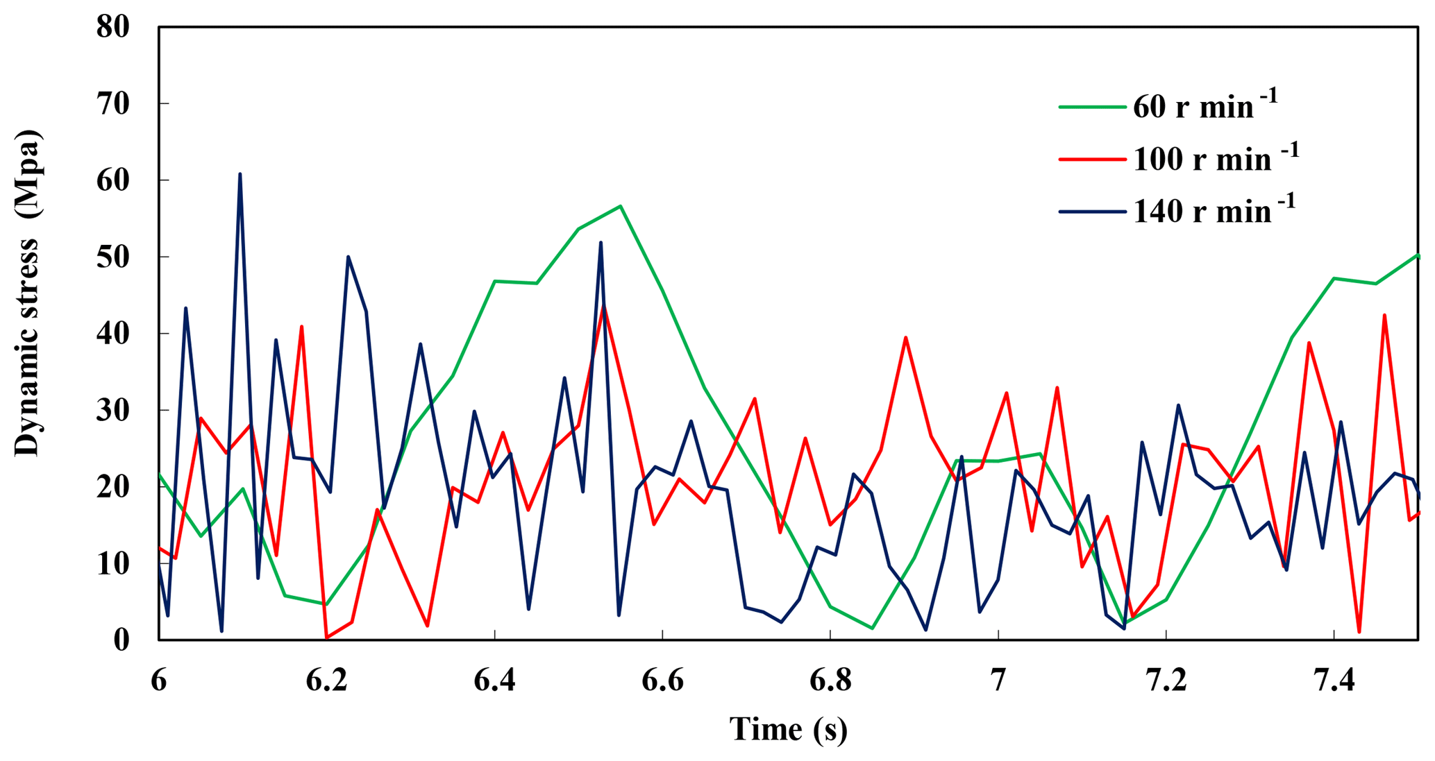
When the speed is 60, 100 and 140 r min−1 respectively, the changes of the maximum stress point in different cycles are shown in Fig. 5. Stress changing period and maximum stress differ with different rotating speed. When the speed is 140 r min−1, the stress peak is the largest, up to 60 MPa. When the speed is 100 r min−1, the stress peak is the minimum.
Additionally, when the rotating speed is 60, 100 and 140 r min−1 respectively, the drill bit lateral force changes in different periods are shown in Fig. 6. When the speed is 140 r min−1, the lateral force reaches a maximum of 40 kN at 6.95 s. At different speeds, the lateral forces tend to stabilize with time. When the rotating speed is 140 r min−1, displacement of assembly at various points in a cycle is shown in Fig. 7a, due to the constraints on both ends of the assembly, there is no displacement in X and Z directions, the other drillstring point has larger displacement changes. When the speed is 140 r min−1, as shown in Fig. 7b, the stress at each node of the drillstring constantly changes within a period. The node with maximum stress is in the middle of the drillstring as indicated by the arrow. The maximum stress reached about 78 MPa at 5.863 s.
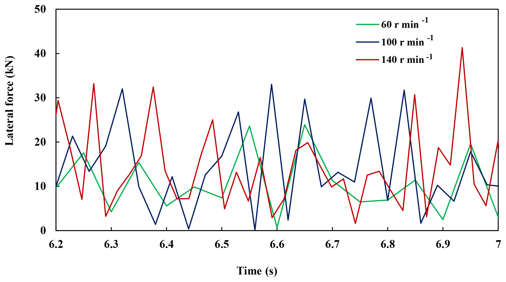
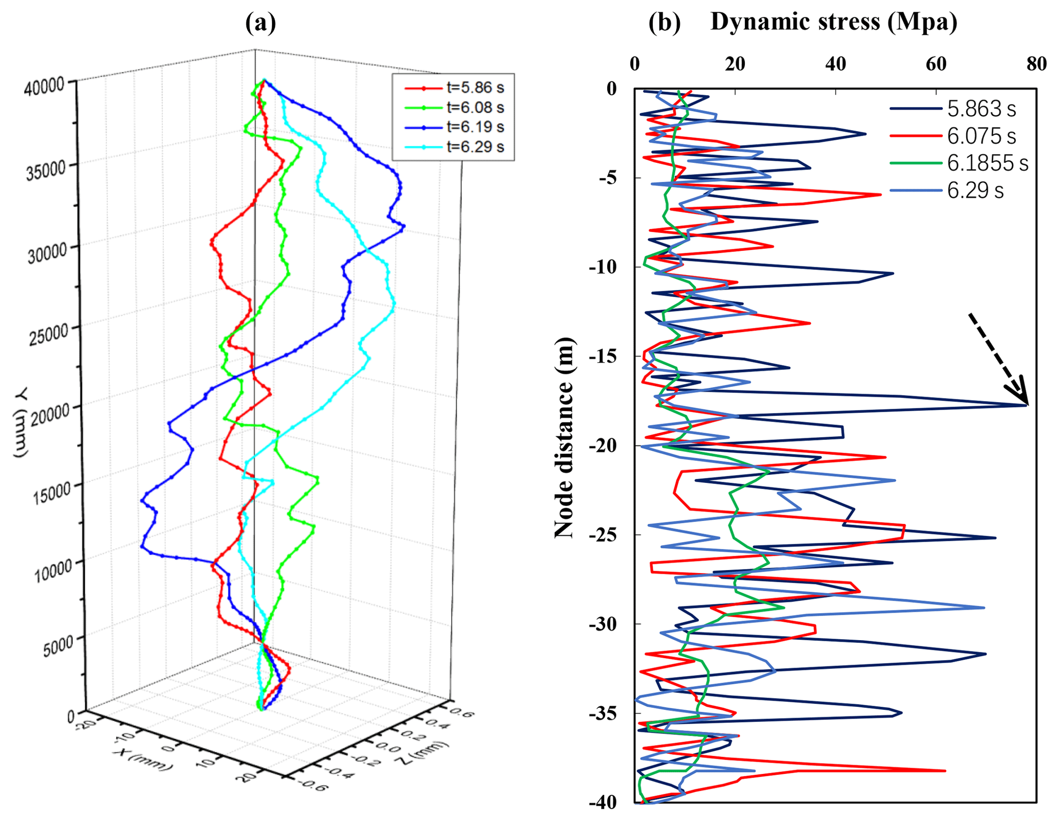
Figure 7The variation of the displacement and the stress of each node in the drill assembly with time.
4.5 Safety evaluation
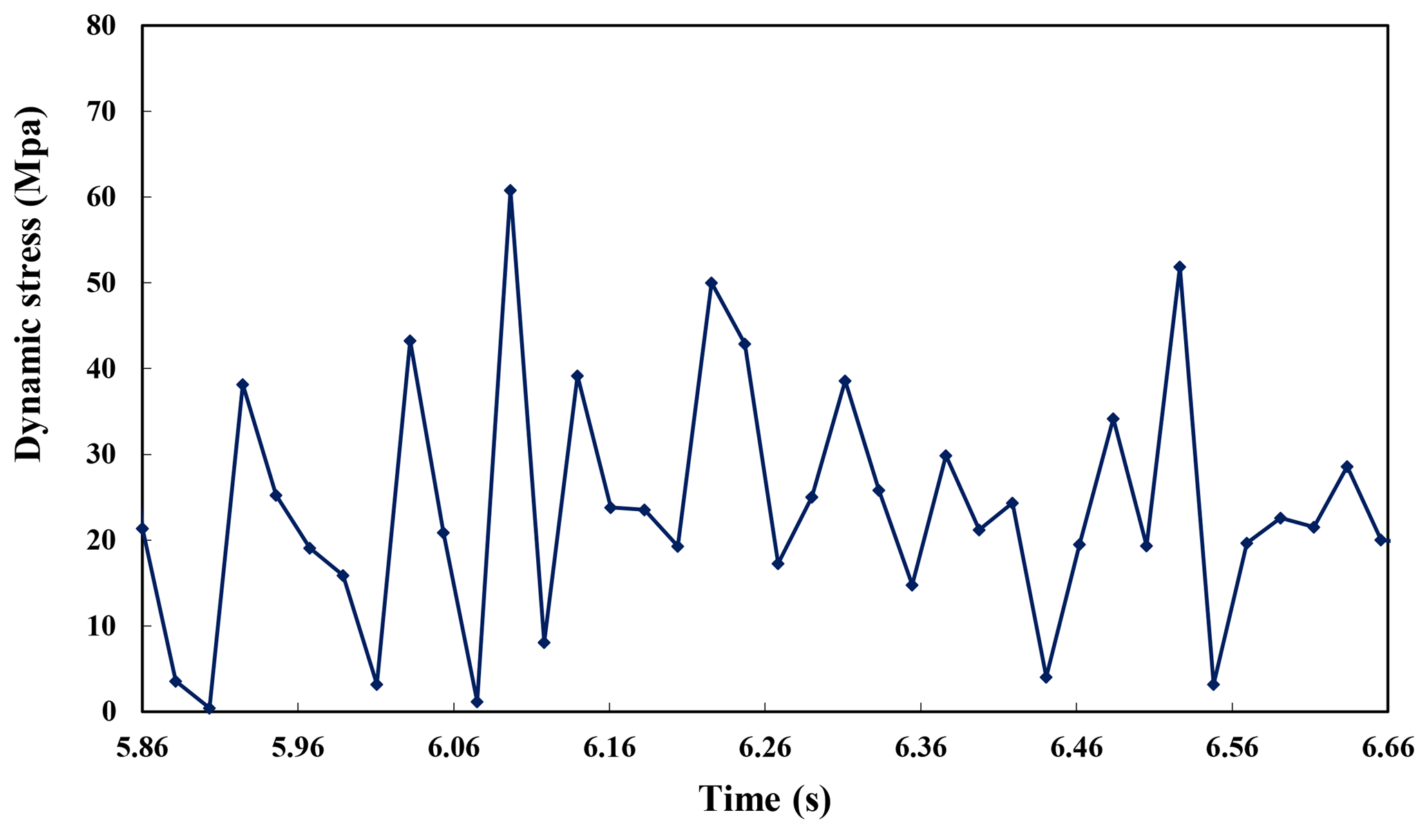
When the rotary speed is 140 r min−1, the dangerous stress point is 14.62 m away from the bottom of the drillstring. The change of stress over time is shown in Fig. 8.
As shown in the Fig. 8, the maximum stress MPa, the minimum stress MPa, and equivalent stress amplitude is (MPa). Since the σ is obviously less than σs and σda<σa, it meets the fatigue strength requirement.
4.6 Experimental vibration data analysis
Direct measurement of stress values is difficult, besides the theoretical research, the measurements of drillstring vibration in in field were carried out by drilling engineer. To understand the intensity of drillstring vibration, Alley and Sutherland (1991) and Tian (2016) used Measurement While Drilling (MWD) to measure vibration parameters, the results show that the drillstring vibrates violently while drilling. The latest measurements were measured by the micro vibration logging tool, which was directly mounted on the drill bit to avoid interference of other downhole tools, so the vibration characteristics of drillstring and the fluctuation of WOB will be truly reflected by the measurements.
The rotary steerable system (RSS) with push-the-bit mode is installed near the bit for directional drilling, the whole drillstring of the drilling system is rotated from the surface by a top drive, which is typically a hydraulically driven mechanism. During directional drilling using RSS, specialized downhole equipment is employed to replace conventional directional tools such as mud motors. For RSS using push-the-bit mode, its push pads in implementing agency alternately in turn pushed against the borehole wall, making the bottom hole constantly under a cycle of nonlinear damping force, by which the movement of the RSS would be transformed to chaos and disorder. Thus, it is necessary and urgent for us to do some thorough research about the dynamic state of RSS. High-sample-rate downhole dynamics sensors were placed at 0.46 m above the bit in the BHA.
We develop a strap-down measurement while drilling (MWD) surveying system that incorporates three-axis magnetometers and three-axis accelerometers arranged in three mutually orthogonal directions (Russel and Russel, 1979). The sensors are installed inside nonmagnetic drill collar that can avoid the external magnetic interferences (Rehm and Garcia, 1989). ax, ay, az are defined as survey signals of triaxial accelerometers on the x, y, z axis respectively. mx, my, mz are defined as survey signals of triaxial magnetometers on the x, y, z axis respectively, the sampling frequency fs is 1 kHz. Assume that the Earth's magnetic field strength as M. Obviously, . Under certain sample frequency, measuring signal is time series and can be expressed as time function. We can use define the lateral vibration of the BHA and use az express the longitudinal vibration.
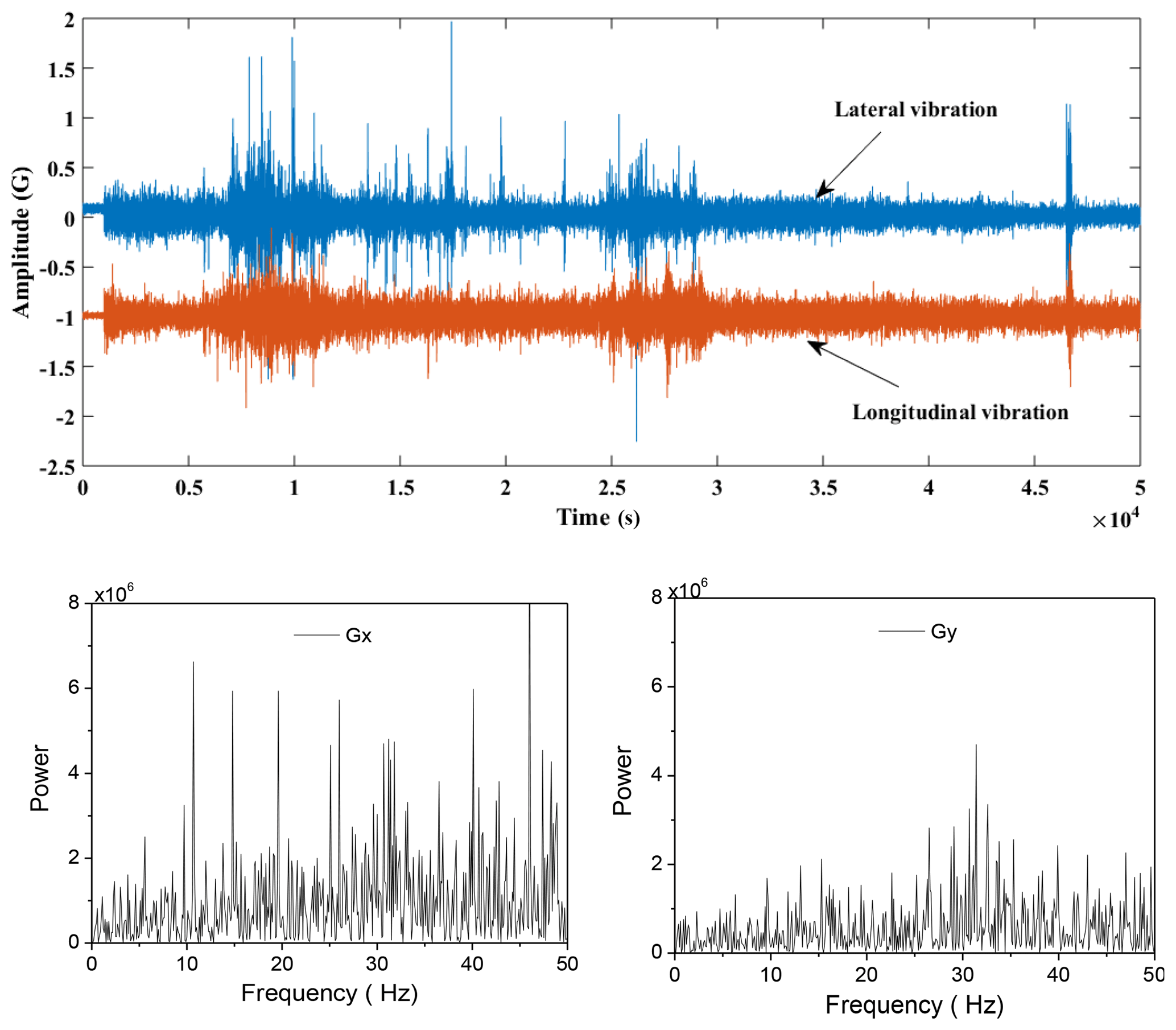
Figure 9The time series of drillstring vibration and the spectrogram of x and y signals of accelerometers, in the case of safety drilling.
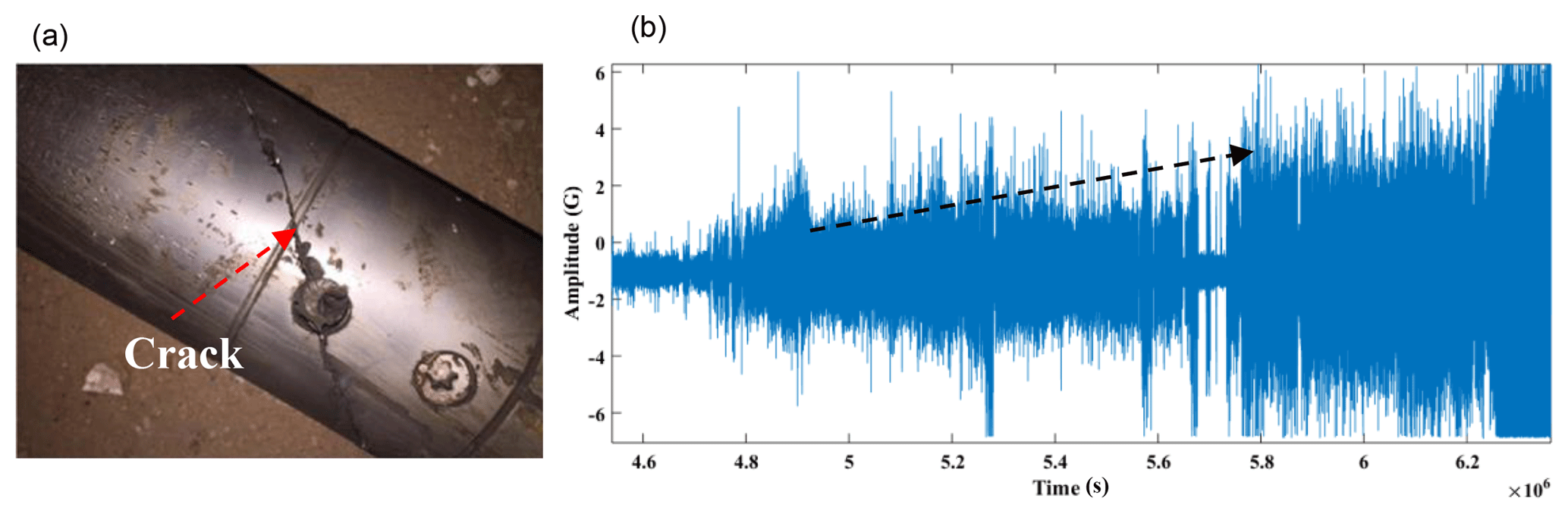
Figure 10The actual photo of the drillstring damage (a) and the vibration signal measured in the early stage of the drillstring damage (b).
As shown in the Fig. 9, the time series of lateral vibration and longitudinal vibration of drillstring were illustrated, and the spectrogram of x and y signals of accelerometers were illustrated subsequently. The vibration data is measured in the case of safety drilling. In the secondary development software as mentioned above, the σ is less than σs and σda<σa, indicates that the working condition is safe. In the other case, if the vibration state of the drillstring is unsafe, the measured vibration signals level will increase, as shown in the Fig. 10, the vibration signal gradually increases until the drillstring is damaged. Simultaneously, we can calculate by the software we developed in this paper, σ≥σs or , reveal the vibration intensity of drillstring is too high to safe.
The vibrations induced in the drillstring are the main reasons for the drillstring failure. To develop practical and commercial computing software about drillstring dynamics is difficult, the model established must take lithology, bit type, drill assembly, damping and contact into consideration, meanwhile through a lot of experiments and experiment data analysis. In this paper, we developed a secondary development software based on commercial finite element software, which reduces large amount of work for calculation method and program verification. The dynamic characteristics of the inherent frequency and dynamic stress of the bottom hole assembly (BHA) were calculated and analyzed, and risk assessment method based on the quantitative vibration intensity was established. Considering the contact and collision between drillstring and borehole wall, taking the whole drillstring assembly system as the research object, the dynamic equation is solved by explicit central difference method in Abaqus, and the dynamic response of drillstring system is obtained. Then a risk assessment method based on quantitative vibration intensity was established and dynamic characteristics and safety of typical drillstring were analyzed. Using the secondary development function of Abaqus to develop specific graphical user interface and command flow to simplify, it is simpler and more effective to analyze specific engineering problems.
The “danger assessment method based on quantitative vibration intensity” established in this paper firstly requires avoiding the critical speed and selecting the ideal recommended speed; if it is not fully realized, the dynamic stress is evaluated, and the vibration intensity is determined according to the fatigue allowable stress and the yield limit of the drillstring. Divided into three grades to assess the reliability of the drill assembly with dynamic stress levels. This method combines the point control to avoid the resonance speed and the interval control based on the dynamic stress level, and forms the quantitative evaluation principle of the vibration risk of the drillstring.
The vibration and internal stress of the drillstring have a positive correlation, downhole measurement can only get the vibration signals and cannot get the magnitude of the stress value, simultaneously, internal stress is easily obtained by theoretical calculation. In this paper we developed a software for secondary development that can quickly get stress values. The combination of the two methods, ability to provide an optimal solution for the safety assessment of drilling tools. In addition, the effectiveness of our reliability assessment method is also proved by experimental vibration data.
The data used to support the findings of this study are included within the article.
The supplement related to this article is available online at: https://doi.org/10.5194/ms-10-79-2019-supplement.
QX, LaH, BL and CY analyzed the data and developed the model; QX and LeH performed the experiments; QX, RW and LeH prepared the figures. QX, LeH and CY wrote and edited the manuscript.
The authors declare that they have no conflict of interest.
The author(s) disclosed receipt of the following financial support for the
research, authorship, and/or publication of this article: This work was
supported by National Key R&D Program of China (2016YFE0202200) and
Natural Science Foundation of China (51704264).
Edited by: Guimin Chen
Reviewed by: three
anonymous referees
Abdo, J.: Modelling of Frictional Contact Parameters of a Mechanical Systems, Int. J. Appl. Mech. Eng., 11, 449–465, 2006.
Abdo, J. and Abouelsoud, A. A.: Analytical approach to estimate amplitude of stick-slip oscillations, J. Theor. Appl. Mech., 49, 971–986, 2011.
Alley, S. D. and Sutherland, G. B.: The Use of Real-Time Downhole Shock Measurements to Improve BHA Component Reliability, in: SPE Annual Technical Conference and Exhibition, 6–9 October 1991, Dallas, Texas, 1991.
Budynas, R. and Nisbett, J.: Shigley's Mechanical Engineering Design, 10th Edn., McGraw-Hill Education, https://doi.org/10.1017/CBO9781107415324.004, New York City, 2014.
Ghasemloonia, A., Rideout, D. G., and Butt, S. D.: Analysis of multi-mode nonlinear coupled axial-transverse drillstring vibration in vibration assisted rotary drilling, J. Petrol Sci. Eng., 116, 36–49, https://doi.org/10.1016/j.petrol.2014.02.014, 2014.
Gupta, S. K. and Wahi, P.: Global axial–torsional dynamics during rotary drilling, J. Sound Vib., 375, 332–352, https://doi.org/10.1016/j.jsv.2016.04.021, 2016.
Huang, W., Gao, D., Wei, S., and Li, X.: A generalized quasi-static model of drill string system, J. Nat. Gas Sci. Eng., 23, 208–220, https://doi.org/10.1016/j.jngse.2015.01.038, 2015.
Jogi, P. N., Macpherson, J. D., and Neubert, M.: Field verification of model-derived natural frequencies of a drill string, J. Energ. Resour.-ASME, 124, 154–162, https://doi.org/10.1115/1.1486018, 2002.
Jones, S., Feddema, C., Castro, J., and Sugiura, J.: Fully Mechanical Vertical Drilling System Delivers RSS Performance in Vertical Drilling Applications While Providing an Economical Alternative to Conventional Rotary Steerable Systems Set-Up for Vertical Hold Mode, in: IADC/SPE Drilling Conference and Exhibition, 1–3 March 2016, Worth, Texas, USA, 2016.
Kapitaniak, M., Hamaneh, V. V., Chávez, J. P., Nandakumar, K., and Wiercigroch, M.: Unveiling complexity of drill–string vibrations: Experiments and modelling, Int. J. Mech. Sci., 101, 324–337, https://doi.org/10.1016/j.ijmecsci.2015.07.008, 2015.
Khulief, Y. A. and Al-Naser, H.: Finite element dynamic analysis of drillstrings, Finite Elem. Anal. Des., 41, 1270–1288, https://doi.org/10.1016/j.finel.2005.02.003, 2005.
Lian, Z., Zhang, Q., Lin, T., and Wang, F.: Experimental and numerical study of drill string dynamics in gas drilling of horizontal wells, J. Nat. Gas Sci. Eng., 27, 1412–1420, https://doi.org/10.1016/j.jngse.2015.10.005, 2015.
Liao, C. M., Vlajic, N., Karki, H., and Balachandran, B.: Parametric studies on drill-string motions, Int. J. Mech. Sci., 54, 260–268, https://doi.org/10.1016/j.ijmecsci.2011.11.005, 2012.
Lin, T., Zhang, Q., Lian, Z., Liu, Y., Zhang, Y., and Chen, Y.: Multi-axial fatigue life prediction of drill collar thread in gas drilling, Eng. Fail. Anal., 59, 151–160, https://doi.org/10.1016/j.engfailanal.2015.09.012, 2016.
Millheim, K., Jordan, S., and Ritter, C. J.: Bottom-hole assembly analysis using the finite-element method, J. Petrol Technol., 30, 265–274, https://doi.org/10.2118/6057-PA, 1978.
Nave, E. D. and Dvorkin, E. N.: On the modeling of oil well drilling processes, Int. J. Comput. Aided Eng., 32, 387–405, https://doi.org/10.1108/EC-03-2013-0093, 2015.
Qu, Z.: Lateral vibration of drillstring under Joint action of inside and outside drill fluid flow, China Petro. Mach., 23, 40–43, 1995.
Rehm, W. A. and Garcia, A.: Horizontal drilling in mature oil fields, in: SPE/IADC Drilling Conference, 28 February–3 March 1989, New Orleans, Louisiana, 1989.
Ritto, T. G., Escalante, M. R., Sampaio, R., and Rosales, M. B.: Drill-string horizontal dynamics with uncertainty on the frictional force, J. Sound Vib., 332, 145–153, https://doi.org/10.1016/j.jsv.2012.08.007, 2013.
Russel, M. K. and Russel, A. W.: Surveying of boreholes, United States Patent US4163324, 1979.
Sampaio, R., Piovan, M. T., and Lozano, G. V.: Coupled axial/torsional vibrations of drill-strings by means of non-linear model, Mech. Res. Commun., 34, 497–502, https://doi.org/10.1016/j.mechrescom.2007.03.005, 2007.
Schmalhorst, B. and Neubert, M.: Dynamic Modeling Software, in: AADE Technical Conference, 1–3 April 2003, Houston, Texas, 2003.
Shor, R. J., Dykstra, M. W., Hoffmann, O. J., and Coming, M.: For Better or Worse: Applications of the Transfer Matrix Approach for Analyzing Axial and Torsional Vibration, in: SPE/IADC Drilling Conference and Exhibition, 17–19 March 2015, London, UK, 2015.
Tian, J., Wu, C., Yang, L., Yang, Z., Liu, G., and Yuan, C.: Mathematical modeling and analysis of drill string longitudinal vibration with lateral inertia effect, Shock Vib., 2016, 6281264, https://doi.org/10.1155/2016/6281264, 2016.
Wang, R., Zang, Y., Zhang, R., Bu, Y., and Li, H.: Drillstring failure analysis and its prevention in northeast Sichuan, China, Eng. Fail. Anal., 18, 1233–1241, https://doi.org/10.1016/j.engfailanal.2011.03.005, 2011.
Wang, R., Xue, Q., Han, L., Sun, F., and Yue, W.: Torsional vibration analysis of push-the-bit rotary steerable drilling system, Meccanica, 49, 1601–1615, https://doi.org/10.1007/s11012-014-9942-9, 2014.
Wang, Z., Wang, R., Wang, F., Qiu, H., and Li, T.: Experiment study of pore structure effects on velocities in synthetic carbonate rocks, Geophysics, 80, D207–D219, https://doi.org/10.1190/geo2014-0366.1, 2015.
Warren, T.: Rotary steerable technology conclusion: implementation issues concern operators, Oil Gas J., 96, 23–24, 1998.
Wilson, J. K. and Heisig, G.: Investigating the Benefits of Induced Vibrations in Unconventional Horizontals via Nonlinear Drill String Dynamics Modeling, in: SPE/IADC Drilling Conference and Exhibition, 17–19 March 2015, London, UK, 2015.
Xue, Q., Leung, H., Wang, R., Liu, B., Huang, L., and Guo, S.: The chaotic dynamics of drilling, Nonlinear Dynam., 83, 1–16, https://doi.org/10.1007/s11071-015-2461-y, 2015.
Xue, Q., Leung, H., Huang, L., Zhang, R., Liu, B., Wang, J., and Li, L.: Modeling of torsional oscillation of drillstring dynamics, Nonlinear Dynam., 1–17, https://doi.org/10.1007/s11071-019-04789-x, 2019.
Yigit, A., Al-Ansary, M., and Khalid, M.: Finite Element Modeling of Drillstrings, Math. Comput. Appl., 1, 158–163, https://doi.org/10.3390/mca1020158, 1996.
Yigit, A. S. and Christoforou, A. P.: Coupled axial and transverse vibrations of oilwell drillstrings, J. Sound Vib., 195, 617-627, https://doi.org/10.1006/jsvi.1996.0450, 1996.
Yigit, A. S. and Christoforou, A. P.: Coupled torsional and bending vibrations of drillstrings subject to impact with friction, J. Sound Vib., 215, 167–181, https://doi.org/10.1006/jsvi.1998.1617, 1998.