the Creative Commons Attribution 4.0 License.
the Creative Commons Attribution 4.0 License.
 | 13 Dec 2019
Kinematic analysis and evaluation of a hybrid mechanism for computer assisted bone reduction surgery
Sinh Nguyen Phu
Terence Essomba
Irwansyah Idram
Jiing-Yi Lai
In severe fracture cases, a bone can be separated into two fragments and it is mandatory to reposition the bone fragments together. This type of surgery is called “bone reduction surgery”. Originally, the operation consisted in manipulating the bones fragments by hand in open surgery. The most advanced technique relies on robotic manipulators providing higher precision and stability. A new mechanical architecture is proposed based on a 3-RPS tripod parallel mechanism combined with a Double Triangular Planar parallel mechanism. Its kinematic and velocity models are calculated and the parasitic motion generated by the tripod mechanism is considered in the final result. The workspace it can generate is compared to the Stewart manipulator, which is a classical mechanism for the targeted application. The use of a robotic manipulator is due to be part of an entire surgical procedure involving a pre-operative simulation software dedicated to pre-planning reduction surgery, namely PhysiGuide. It is used to measure the kinematic associated with bone fragments manipulation and transfer it to the robot during the intra-operative phase. Simulations are then performed based on a real patient's fracture images showing the suitability of the present mechanism with bone reduction surgery.


In Human anatomy, limb bones are more exposed to potential fractures due to their location and due to their longitudinal geometry. According to medical data history, the thigh bone, namely the femur, is the bone that has the highest involvement rate in fracture incidences with around 37 per 100 000 people per year (Arneson et al., 1998; Zlowodzki et al., 2006). Some cases of broken bones require a specific type of surgery before recovering: the bone reduction surgery. In most critical cases indeed, the bone is not only fractured but its two pieces can be separated by a certain distance. The bone reduction surgery consists in relocating the different pieces of the same bone in their original position. During this surgical procedure, the patient's anatomy must be “opened” to allow a physical access to the bone pieces. Once accessible, the surgeons can displace the bones to their original configuration. Because of the natural recall force applied by the patient's anatomy (muscular tissues and tendons), the surgeons have to use a considerable amount of physical strength to relocate to bones.
Later, in order to suppress the risk associated with the “open” type surgery (bleeding, infection, etc.), a minimally invasive version of bone reduction surgery has been developed, which is a general tendency in surgery. The reduction is performed by inserting nails into the bone pieces. These nails are then manipulated to reposition the bone pieces. Although this technique represents less risk for the patient, it also requires a higher level of dexterity from the surgeon since there is no direct vision of the broken bone. During the operation, their position are consequently monitored by intra-operative image. The surgeon in charge of the reduction procedure will then adjust the position of the bone pieces based on the real time images received. But minimally invasive reduction surgeries are still performed using a high strength to reposition the bones. And when surgical implants are required, the bones must be maintained in position the time the implant is fixed. In addition, due to the stress generated by the muscular tissues, there is always a residual motion of the bones parts when they are released. This can cause a misalignment between the bones and the implant after its installation. Another problem is the hazard environment of the image guided surgery. Unlike patients, surgeons will suffer from repeated exposures to the radiation generated by the medical imaging system.
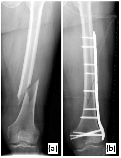
Figure 1Fracture of a patient's femur (a). Result of reduction surgery and implant installation (b).
To solve the problems associated with manual bone reduction surgery (both opened and minimally invasive), a technique based on the use of specialized mechanism has been developed. The concept consists in fixing the mechanism base to one bone piece and the mechanism end effector to another bone piece. By operating the mechanism joints, a motion is generated between its base and its end effector. By extension, a motion is then performed between one bone piece and the other, based on the mechanism kinematics. To perform a complete bone reduction, it is required to manipulate one of the bone fragments by moving it along three linear direction and rotating it around three different axes. Therefore, a total of six Degrees of Freedom (DoF) is required: three linear DoF and three angular DoF. Also, in order to improve the fracture surface matching between the two fragments, it is advantageous to provide a rotation about the bone longitudinal axis. Several research works can be found in the literature as listed in the three coming sub-Sections. However, this particular type of robotic assisted surgery does not seem to attract as much attention as other topics such as laparoscopy or orthopedic surgery for example. One explanation is that the earliest application of this kind has been reported in 1999. This makes it a relatively young topic compared to neurosurgery, which is about two times older (1985). If the focus is given on mechanism concepts, the literature review of robotic bone reduction surgery can be divided into several categories.
1.1 Embedded parallel architectures
The first bone reduction surgical robot has been reported in 1999 (Seide et al., 1999). It is composed of two cylindrical modules that are connected by a hexapod mechanism of 6 legs and 12 spherical joints. These cylindrical modules are called Ilizarov fixators and are commercially available. That mechanical architecture is able to displace one cylinder with 6 DoF from the other. Each fixator is mounted on one piece of a longitudinal bone by surrounding the patient's limb. So the hexapod mechanism can reposition the bone pieces together. This device has been tested on 16 patients presenting deformities or fractures of the tibia.
Since then, the concept of fully embedded hexapod architecture has been often used for the robotically assisted reduction surgery of longitudinal bones. In 2004, another hexapod has been used for bone reduction surgery (Seide et al., 2004). A manually adjusted hexapod has been designed to manipulate two arc fixators attached to one piece of the bone each. A specific software was developed to allow the individual control of 6 DoF. The prototype has successfully performed the fracture reduction of four patients. The Taylor Spatial Frame is a hexapod mechanism dedicated to the bone reduction (Taylor, 2008). In 2006, a study has been reported about the use of the device on 10 pediatric patients from 8 to 15 years (Al-Sayyad, 2006). The same mechanical architecture has been used for the implementation of a computer-assisted orthopaedic procedure based on 3-D CT-Scan image in 2012 (Tang et al., 2012). It was tested on the fracture reduction of 10 bovine femurs.
1.2 Embedded serial architectures
Back in 2000, another kind of architecture has been tried for this application. Although the mechanism is still full embedded into the patient's anatomy, a serial architecture is used (Moorroft et al., 2000). The concept relies on a proximal and a distal clamp that are attached to one bone piece each. Both clamps are connected together by a serial mechanism of two linkages. There are one sagittal prismatic joint between the proximal clamp and a linkage, one transversal and one longitudinal prismatic joint between the distal clamp and a linkage and one spherical joint between the two linkages. These 6 DoF are manually adjustable individually by the mean of translation screws. The device has been tested on 22 tibial fractures. The kinematic analysis of two other devices sharing the same concept have been reported in 2002. Dynafix and Orthofix fixators are embedded mechanism for fracture reduction and bone deformity (Kim et al., 2002). Both of them are commercially available. The Dynafix is composed of two telescopic pin clamps, a central universal joint and two sets of revolute joints. The Orthofix is made of two straight pin clamps with a central body that provides an axial adjustment. Both sides have a ball-and-socket joint. The results of simulation experiments using the Dynafix have been later reported in 2006 (Koo et al., 2006). While the Dynafix and Orthofix are fully mechanical devices, another new prototype instrumented with rotary sensors has been designed for a better accuracy in 2007 (Koo and Mak, 2007).
1.3 Deported mechanisms
The bone reduction surgery can be performed using another concept of mechanism that here is referred to as “deported” mechanism. By “deported” mechanism, it is understood that while the mechanism end effector is still fixed with the patient's anatomy (bone piece), its base is attached to an external reference. The earliest instance of such system was reported in 2004. The system RepoRobo was an industrial robotic manipulator, namely Stäubli RX130, reprogrammed for bone reduction surgery (Füchtmeier et al., 2004). A software has been programmed in order to control the robotic manipulator in motion or in force. A force sensor is integrated in the robot end effector for the force feedback. In 2008, another industrial robotic manipulator has been reprogrammed for this application. This time, a Stäubli RX90 was used as part of a tele-operated system for bone reduction surgery (Westphal et al., 2008). The operator manually controls the manipulator using a standard joystick. The manual navigation is guided by intra-operative fluoroscopy. A high precision robot with a particular architecture has been designed in 2008 for hip fracture reduction. It has been combined with a navigation system based on fluoroscopy (Joung et al., 2008). The mechanical architecture is composed of three successive revolute joints along three different directions, followed by three prismatic joints. The end effector is a ring that surrounds the patient's anatomy. The same year, a robot based on a hexapod architecture has been designed for the reduction of femur fracture (Graham et al., 2008). The robot is placed horizontally and its end effector is attached to the patient's foot using an adapted holster. The manipulator is manually controlled by the mean of discrete point trajectories. In 2015, another hexapod architecture has been developed for a similar concept (Du et al., 2015). However this time, the mechanism is placed vertically below the patient's leg and its end effector is attached to the patient's bone directly. The whole hexapod is mounted on a vertically adjustable platform.
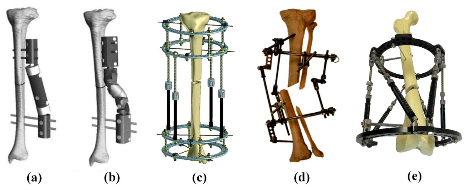
Figure 2Examples of bone reduction mechanism. (a) Orthofix fixator (Kim et al., 2002); (b) Dynafix fixator (Kim et al., 2002); (c) Ilizarov apparatus (Zamani and Oyadiji, 2009); (d) Ortho-SUV Frame (Solomin, 2013); (e) Taylor Spatial Frame (Mackie Orthopaedics, 2016).
According to the literature review of mechanisms and robotic systems for bone reduction surgery, several conclusions can be made about this topic:
-
This specific medical robotic application is quite recent compared with robotic orthopedic in general. So the state of the art in this domain is relatively limited.
-
Existing bone reduction robotic systems are also limited in diversity. Although they can be regrouped in three conceptual categories, only three types of mechanical architectures can be reported.
Parallel mechanical architectures seem more promising as they offer higher stiffness, higher accuracy, higher payload and low inertia in comparison to serial architectures. But they provide smaller workspace while it is an important aspect in bone reduction surgery. For this reason, some scholars tried to design new types of hybrid architectures by combining the advantage of several structures. In 1995, Etemadi-Zanganeh and Angeles (1995) classified the general hybrid parallel manipulator into 3 groups: hybrid system of serial chains, hybrid series-parallel chain and hybrid parallel-serial chains. According to their definition, hybrid parallel-serial chains have a series of parallel manipulators connected in series. For instance, in 1998, Romdhane (1999) presented a new 6-DoF hybrid robot (HS-PM) that is composed of two 3-DOF spatial parallel mechanisms. One 3-DoF spatial robot provides 3 rotation movements and one 3-DoF spatial robot provides 3 linear movements. The advantage of this mechanism is that the orientation workspace separated from the position workspace. Zheng et al. (2004) presented a new kind of 6-DoF hybrid robot by serially connecting two 3-UPU spatial parallel mechanisms. Because 3-UPU parallel manipulators could offer pure translation or rotation depending on specific mounting and legs geometric conditions, it is easy to decouple the robot motion into pure translations and pure rotations. In 2015, Hu and Yu (2015) presented a method to solve inverse kinematic and dynamic problem of a novel 6-DoF hybrid manipulator constructed by one spatial UPR +RPS + UPS parallel robot and one 3-UPS/UP parallel robot. The UPR + RPS + UPS parallel robot has one transitional and two rotational DoF and the 3-UPS/UP parallel robot has one translation and two rotation DoF. In 2009, Lu et al. (2009) also presented a kinematic and workspace analysis of another 6-DoF hybrid parallel-serial robot. It has two spatial SP + SPR + SPU manipulators connected in series. Recently, in 2018, Nayak et al. (2018) developed a kinematic model of a 3-RPS-3-SPR serial-parallel mechanism. It is constructed by one proximal 3-RPS parallel mechanism and on distal 3-SPR parallel mechanism. In this study, the proposed hybrid 6-DoF parallel robot is constructed by a 3-DoF planar parallel robot and a 3-DoF spatial parallel robot. The planar manipulator provides two linear and one rotation motions (x, y and yaw) and the spatial manipulator provides one linear and two rotation motions (z, roll and pitch).
A 3-DoF planar manipulator consists of a moving platform connected to a fixed base by three identical limbs. There are several different serial chain architectures that categorized it into seven different sub-types, namely, RRR, RPR, PRR, RRP, RPP, PRP and PPR (excluding PPP) by Merlet (1999). And many other configurations have been introduced and studied. Arakelian et al. (2011) introduced a novel 3-DoF planar parallel manipulator with larger rotation capability. Zarkandi (2011) proposed a novel planar Star Triangle (ST) parallel manipulator with two platforms, one fixed Triangle platform and one Star mobile platform. They are connected via three legs that are made of PRP joints. Seo et al. (2009) designed a new planar 3-DoF parallel mechanism with continuous 360∘ rotational capability. This robot has two circle platforms, one fixed circular guide and one circular mobile platform, connected by three PPR legs.
Similar to the 3-DoF planar, a 3-DoF spatial manipulator is composed of a moving platform connected to a fixed base by three identical limbs. They may provide only pure relative rotations of the moving platform about a fixed point, pure relative translations of the moving platform and the base or two translations and one rotation (2T1R). For instance, Carretero et al. (2000) developed a 3-DoF parallel manipulator based on the 3-PRS architecture but his proposed mechanism has three active prismatic joints lie on a common plane. Xie et al. (2012) proposed a decoupled 3-DoF parallel mechanism for tool head. The advantage of this mechanism is that it has no parasitic motion between the moving platform and the base. Li et al. (2016) introduced an over-constrained 3-DoF parallel manipulator with 2-RPU & SPR type. The base platform is connected to the moving platform by two identical RPU limbs and one SPR limb. Recently, in 2018, Zhang et al. (2018) introduced a novel 3-DOF 2R1T parallel manipulator with two UPU and one SP identical chains structure for machining applications.
The objective of the present study is to propose a manipulator dedicated to bone reduction surgery, based on a new mechanical architecture. Indeed, all the systems quoted above use very standard architecture (hexapod, Stäubli, etc.) which may not be fully optimized for the application. A new mechanical architecture is defined based on the kinematic associated with bone reduction surgery. The system will be dedicated to reduction of broken femurs, which is the most exposed bone to fracture incidences. The robotic system is combined with a software dedicated to pre-operative bone reduction planning that has been programmed locally. The present work is organized as followed: the next Section will introduce the new mechanical architecture for the manipulation of bone fragments, including kinematic studies and singularities. In the third Section, a workspace comparison with a standard mechanism for bone reduction is provided. The fourth Section describes the bone reduction surgery procedure that involved a medical simulation software and the mechanism. The results of a simulation using the proposed mechanism on that procedure based on the case of a real patient's broken femur is shown. The conclusion of the present study is provided in Sect 5.
A mechanism based on a hybrid mechanical architecture has been defined to perform motion required to manipulate the bone fragments in the reduction surgery. Its kinematic and velocity models are provided in this Section and its singular configuration are identified.
2.1 Mechanical Architecture Concept
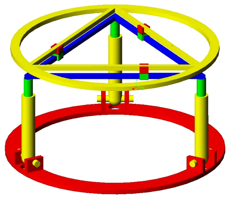
External ring fixators are widely used in orthopedics for fracture fixation, bone lengthening, and deformation correction purposes. The clinician typically brings the bone fragments to an anatomically desired position by changing the length of the rods connecting the fixator rings. This task is accomplished by the clinician based on the experience and expertise. As an alternative, the commercial system exists where the same task is automated with the help of an accompanying software that is implemented with the mathematical model of the fixator. The Stewart platform was selected considering its analogy with widely used Ilizarov's external fixation device. The Stewart platform has several advantageous characteristics to act as a robotic fracture reducer, including high stiffness and precision, acceptable repeatability, 6 DoF (3 angular and 3 linear) and high load to weight ratio. But the workspace of this architecture appears to be limited. Indeed, the range of angular motion rapidly decreases as soon as the end effector moves away from the workspace center. Also, the possibility of rotating the bone around its longitudinal axis is very limited, while it is an important feature for bone reduction in order to guaranty the surface correspondence of bone fragments. It is proposed to use a double triangle planar parallel manipulator with an equilateral triangular fixed and moving platforms respectively fixed to the proximal and distal fragments of the fracture bone, using pins or wires. This double triangle structure is composed of one 3 DoF parallel manipulator using 3 Revolute–Prismatic–Spherical (RPS) introduced by Hunt (1983) and one Triangular planar parallel robot using 3 PRP arms suggested by Daniali et al. (1993). The concept of this novel robot is shown in Fig. 4. The arms of the 3-RPS mechanism consist in connecting the base by the first joint (R) to the moving platform by the last joint (S-joint). The planar manipulator is a special symmetrical closed-loop mechanism that is composed of a pair of triangles: one base and one platform. The platform triangle is placed on the top of the base triangle and is moved by 3 PRP arms fixed to the edges. The first prismatic joint of each arm allows them to slide along each edge of the base triangle. A planar parallel mechanism has the specific performance, whereas the links are moving in the planar motions. The RPS manipulator has 2∘ of orientation freedom and one degree of translation freedom. One advantage of the present architecture compared to the Stewart mechanism is that the double triangular structure can provide a much larger range of longitudinal rotation of the bone fragment for most angular position of the end effector given by the tripod mechanism.
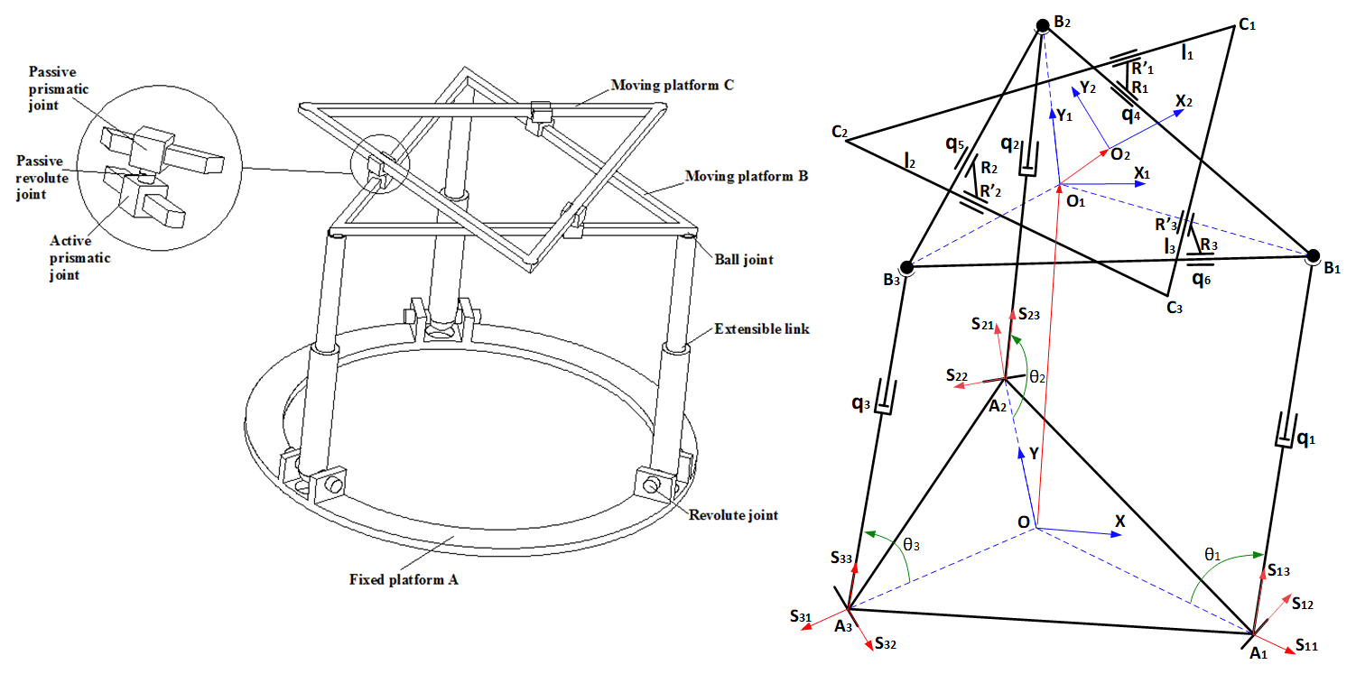
Figure 3Schematic of the basic concept and kinematic representation of the mechanical architecture.
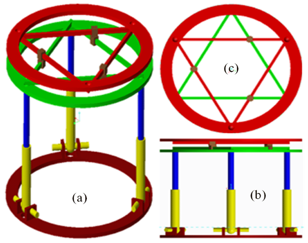
Figure 4Schematic of the basic concept and kinematic representation of the mechanical architecture.
2.2 Kinematic Analysis of the Mechanism
In order to determine the kinematic model of the present mechanism, several reference frames are attached with different items of the mechanism. The reference frame is attached with the fixed base A with O, the center of the equilateral triangle A1A2A3 that orthogonal to the z-axis. The frames and are respectively attached with the moving platforms B and C. They are represented by the equilateral triangles B1B2B3 and C1C2C3 and they are respectively orthogonal to axis z1 and z2. The moving platform B is connected with the spatial 3-RPS parallel mechanism by three passive spherical joints located at the triangle corners B1, B2, and B3. The fixed base has three passive revolute joints at the corners of the equilateral triangle A1A2A3. The moving platform B is put in motion in the reference frame by the mean of three active prismatic joints, each located between the revolute and spherical joints of each RPS linkage.
It is assumed that the mechanism end-effector is located by the point O2 of the moving platform C. Its linear position in the coordinate system is described by x, y and z variables. The orientation of the end-effector is given by the three angles α, β and γ. The general coordinates of the ith joints are given by the length qi ().
The position of the revolute joints A1, A2 and A3 in are given by the vectors below:
With ra, the radius of the circumcircle of center O passing by A1, A2, and A3. The position of the spherical joints in the coordinate system of the moving platform B are written as below:
With rb, the radius of the circumcircle of center O1 passing by B1, B2, and B3.
And the corners C1, C2, and C3 of the moving platform C in are located as followed:
The position of spherical joints Bk () given in in Eq. (2) can be expressed in as followed:
Where qk (with ) is the prismatic joint variable directed by the vector sk3 as seen in Fig. 3. And where OO1 gives the coordinates [x1 y1 z1] of the center of the moving platform B, expressed in and R is the orientation matrix of frame with respect to with α, β, and φ being the Roll-Pitch-Yaw and written as:
Where c∗ and s∗ correspond to cos (∗) and sin (∗), respectively.
Similarly, the original position of the center of the moving platform C in the frame is given by:
With d, the distance between the moving platform B and the moving platform C.
The 3-RPS parallel mechanism is one of the lower-mobility parallel mechanism which has an important kinematic feature is parasitic motion (Carretero et al., 2000; Li et al., 2011). The 3-RPS parallel mechanism generates three parasitic motions: two translations along axis x, y and one rotation about the z-axis with respect to the fixed frame. In other words, the moving platform B has a small parasitic motion of the fixed base (x1, y1, φ). These unwanted parasitic translations (x1, y1) are compensated by the linear motion of the 2nd moving platform.
Hence, the position vector of the end effector O2 expressed in the fixed frame is given by:
Considering the constraints applied by the revolute joints at points A1, A2 and A3, the parasitic motions of the moving platform B are calculated.
Where sk2 (with k=1, 2, 3) gives the direction of the axis of rotation for the angle θk as seen in Fig. 3. From Eq. (9), it can be found that:
The actuating lengths of the links for a prescribed position and orientation of the moving platform B are obtained by taking the Euclidean norm of the Eq. (4) as bellow:
By solving the Eqs. (4) and (5), the rotation angle θ1, θ2 and θ3 of the kth legs can be written as:
The position vector of the active prismatic joints R1, R2, and R3 expressed in frame .
And assuming , the distance between the corner Ck moving platform C and the closest passive prismatic joint , namely , and respectively, the position of expressed relative to O2:
In the frame , the position the passive prismatic joints are calculated as followed:
Where γ is the rotation angle of the moving platform C around z1-axis and Rz(γ) is the rotation matrix around z1-axis of angle γ.
The coordinate constraints of the revolute joints between two prismatic joints Rk and can be defined as followed:
By solving Eq. (20), the length of the active prismatic joints q4, q5, q6 are determined as followed:
2.3 Velocity Model and Singular Configurations of the Mechanism
In order to identify the mechanism singular configurations that could result trajectory problems, its velocity model is studied to isolate the Jacobian matrices. The velocity model of the mechanical architecture can be obtained by differentiating Eq. (8) with respect to time. In order to simplify the calculation, it is possible to separate this mechanism architecture into two parallel mechanisms: one is the velocity model of the 3-RPS parallel mechanism and another is the velocity model of the 3-PRP parallel mechanism. The velocity model of the 3-RPS mechanical architecture is calculated by reformulating Eq. (4) as followed:
Where sk3 is the unit vector directing the three legs qk (Fig. 3). Equation (5) is then substituted and differentiated to obtain:
Where ϑk is the angular velocity of leg kth and ω is the angular velocity of the moving platform B expressed in the fixed platform. This yields:
The parasitic motion given in Eqs. (10) to (12) is differentiated with respect to time to obtain:
Where .
By setting up Eqs. (26) to (29):
Where
The velocity model of the double triangular mechanical architecture is obtained by directly differentiating Eqs. (21) to (23) and arranging as followed:
Where
For the RPS tripod mechanism, the forward singular configuration is determined by using the Jacobean matric JB to solve the following equation:
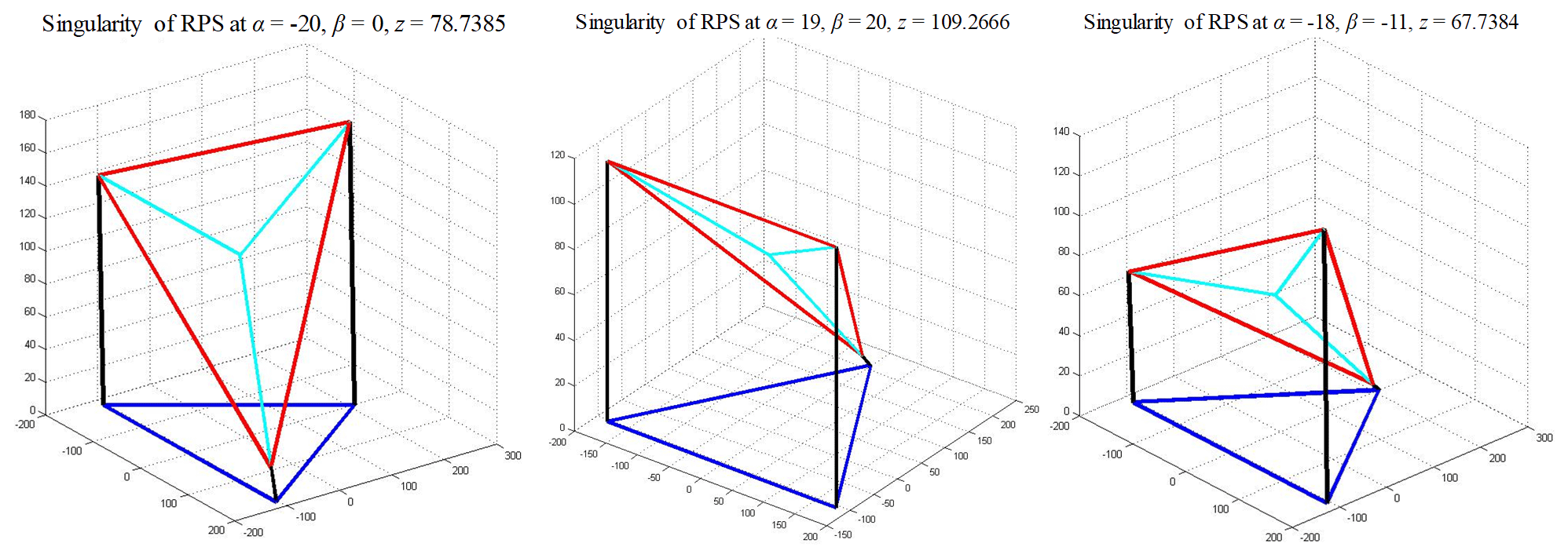
In this specific application, the singularity loci happened in the range of workspace will be considered. Figure 5 shows the singularity distribution of RPS mechanism in range of workspace −20∘ < α < 20∘, −20∘ < β < 20∘. According to the present simulations, there is a risk for the tripod mechanism to reach a singularity when the z coordinate goes from 0 to 111.8 mm. Several points in Fig. 5 are selected as examples to present the singularity configurations in Fig. 6. These configurations are similar to RO-type singularity that classified in Zlatanov et al. (2002) and Li et al. (2015).
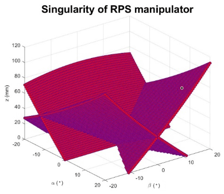
Figure 5Singularity distribution of RPS mechanism in range of workspace −20∘ < α < 20∘, −20∘ < β < 20∘.
For the double triangular mechanism, the inverse singularity is identified by using the Jacobian matric JC to solve the following equation:
By solving this equation, the first singularity condition will be:
In this configuration, the moving platform B of the double triangular mechanism will be at the same position as moving platform A. The forward singularity is found by using the same method with the Jacobian matrix JD. This yields the following equation:
By substituting Eqs. (21) to (23) into Eq. (51):
Assuming , the solution is written as:
The inverse singularity conditions given by Eqs. (48) and (52) lead to the same configuration illustrated in Fig. 7.
The mechanism introduced and studied in the previous sub-Section is made of two different architectures. The first one, a 3-RPS parallel mechanism performs two angular DoF and one linear DoF. The second one, a 3-PRP parallel mechanism provides one angular DoF and one linear planar motion of 2 DoF. The objective of this Section is to compare the presented mechanism in terms of workspace performance to the Stewart manipulator that is widely used in bone reduction surgery.
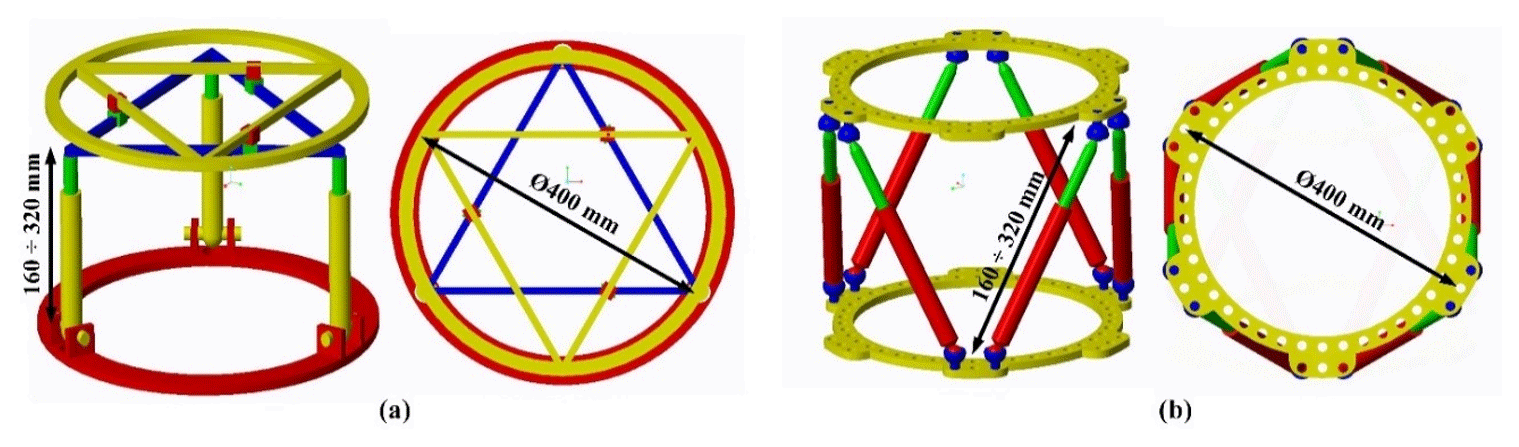
Figure 8General dimensions of the proposed hybrid mechanism (a) and the Stewart manipulator (b).
The workspace of the proposed mechanism is presented and compared with the Stewart manipulator. The mechanism workspace is shown in two different coordinate systems: (x, y, z) and (α, β, γ). A range of translational motion (x, y, z) and the orientation angles (α, β, γ) are discretized into sampling points with a desired resolution. For each point of the workspace, the corresponding mechanism input variables (q1, …, q6) are calculated using the inverse kinematics model given in Sect. 2.2 to verify if the point is reachable. Then, the qi values are checked to insure they are within the stroke range limits given by .
In order to estimate the contribution of the proposed mechanism, its workspace is compared to the Stewart platform which is the most commonly used architecture in the medical application. And to ensure a fair comparison, the Stewart platform and the hybrid mechanism are set with the same general dimensions as illustrated in Fig. 8. Their input variables range of motion are also adjusted similarly. Their upper and lower rings are set to 400 mm diameter. The allowed range of motion of the input prismatic joints is from 160 to 320 mm for the tripod part of the hybrid mechanism and for all the Stewart manipulator joints. The range of motion of the double triangular part of the hybrid mechanism is from 120 to 325 mm. This range is directly imposed by the size of the ring. The available angular motion of the spherical joints is fixed at the range of −20 to 20∘.
For each mechanism, the workspaces in the (x, y, z) coordinate system are respectively displayed in Fig. 9. It reveals that the maximum ranges of motion are measured at 155 mm along x axis, 150 mm along y axis and 165 mm along z axis. But the available range of motion on the (xy) plane rapidly decreases when the z coordinate exceeds a certain range that is measured to 90 mm. Therefore, the maximum ranges along x and y are only available for a range of 90 mm along z axis. On the other hand, the proposed hybrid mechanism seems to offer a much larger workspace on the (xy) plane: 197 mm along x and 194 mm along y axis, which represents an improvement of 27 % along x and 29 % along y. The range of motion along the z axis appears 3 % shorter than for the Stewart manipulator. However, the range of motion in the (xy) plane does not suffer from the deterioration observed in the Stewart manipulator. Indeed, the horizontal planar workspace remains stable for all available positions along the z coordinate.
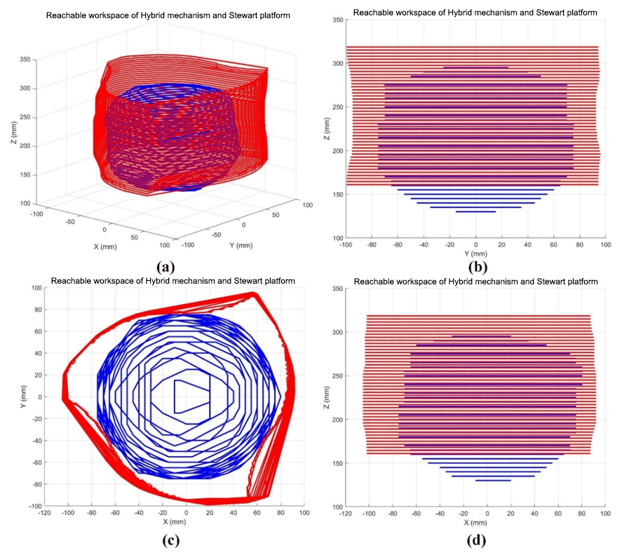
Figure 9Linear workspace representation of the hybrid mechanism (red) and the Stewart platform (blue) in the (x, y, z) coordinate system.
Although one mechanism can reach a certain linear position, it is necessary for bone reduction surgery to maintain an angular workspace large enough to perform the appropriate bone rotations. The proposed hybrid mechanism is also compared to the Stewart manipulator in terms of angular workspace. Obviously, their respective available range of angular motion will vary with the linear position of their end effector. In order to compare them, their angular workspaces are displayed in an (α, β, γ) coordinate system for two different linear positions. The angular workspace is first calculated for both mechanisms homing position and shown in Fig. 10a. A second linear position has been chosen as the final position of a bone reduction trajectory simulation from a real clinical case that will be presented in Sect. 4.2. The angular workspace has been calculated for this position and displayed in Fig. 10b to investigate the suitability of both mechanisms for bone reduction surgery. All data related to both mechanisms angular workspace are shown in Table 2.
Table 1Ranges of angular motions at homing and bone reduction target positions of the hybrid mechanism and Stewart manipulator.
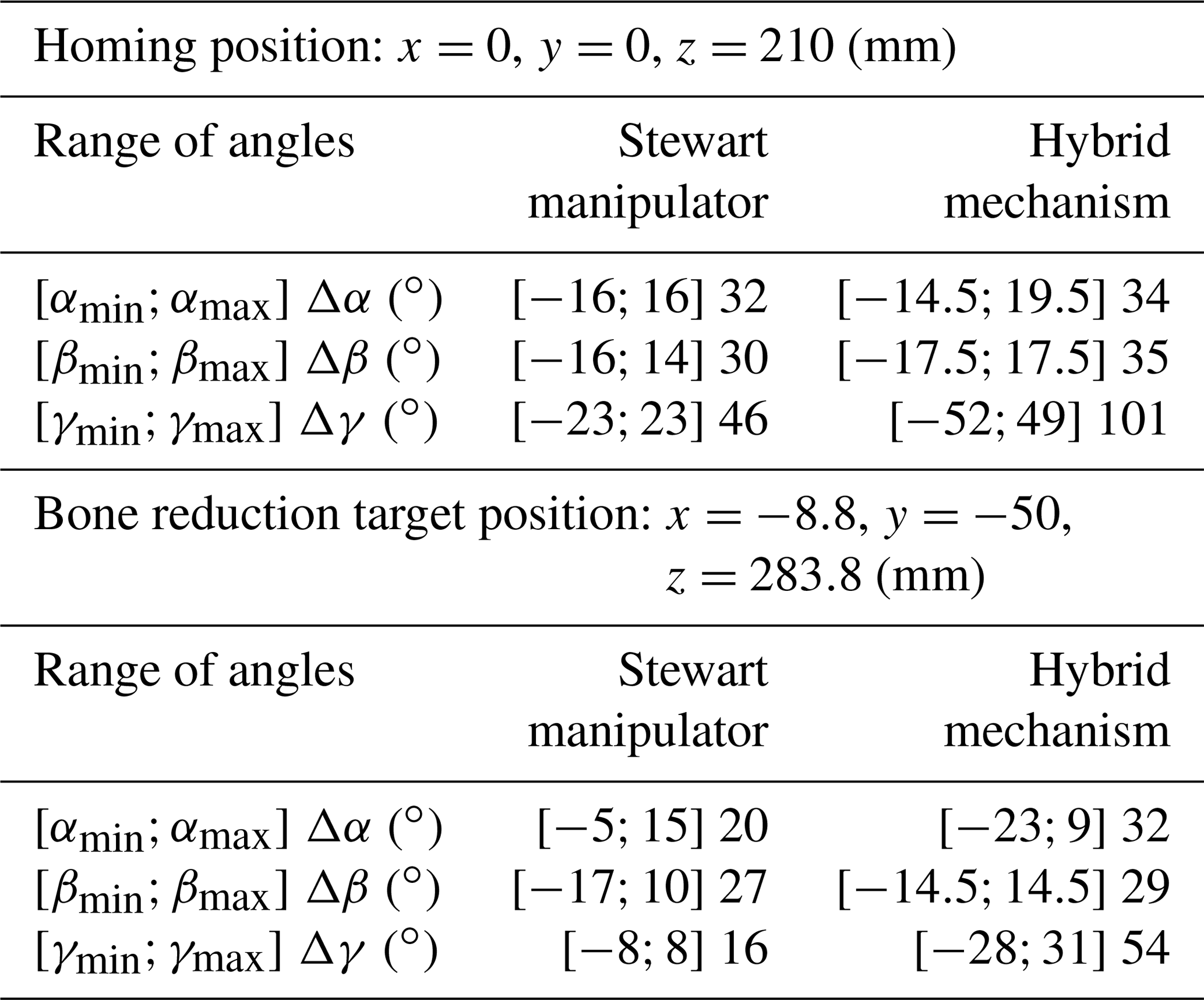
It reveals that the hybrid mechanism has a slightly larger orientation workspace for the angular variables α (+6.2 %) and β (16.7 %). For the angular variable γ, the available range of motion is much higher than the Stewart manipulator (+128 %). And the other hand, that range of motion on that angle is stable and does not vary with the other angles α and β. At bone reduction target position, the ranges of angular motion show a decrease of both mechanisms' workspace. This time, only the hybrid mechanism has a slightly larger workspace for the β angle only (+7.4 %) and it shows a much larger range of angles α (+60 %) and γ (+237.5 %). This demonstrates that the hybrid mechanism has better capacity of maintaining a large and stable orientation workspace. These results confirm the predictive assumptions stated in Sect. 2.1 and validate the contribution of the proposed mechanical architecture for bone reduction surgery. On the other hand, it is noted that all the singular configurations identified in Sect. 2.3 remain outside of the mechanism workspace.
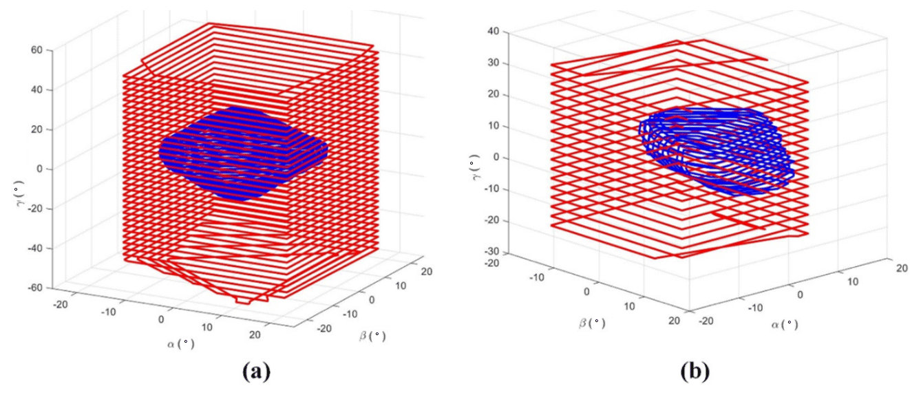
Figure 10Angular workspace representation of the hybrid mechanism (red) and the Stewart platform (blue) in the (α, β, γ) coordinate system at homing position (a) and at bone reduction target position (b).
The feasibility of computer-assisted bone reduction surgery using the presented mechanism is now tested. Prior to operating the robotic manipulator, an entire pre-operative procedure involving a simulation software must be completed. This procedure is described below.
4.1 Pre-operative Simulation Method
The task of the mechanism studied above is to perform the required motions to manipulate bone fragments in bone reduction surgeries. While the base of the mechanism is attached to one fragment, the moving platform 2 is attached to the other one. But the operating this mechanism is only the last phase of a whole surgery that also includes pre-operative planning. Indeed, it is planned that the mechanism will automatically generate the bone reduction, i.e. the repositioning of the bone. The motions that the mechanism will have to perform is determined during the pre-operative phase by the use of a specific software, named PhysiGuide. It has been developed by the Bio-images and Clinical Assistant Laboratory of the National Central University (NCU) to carry out simulation and to provide surgical planning for bone reduction (Lee et al., 2014). In the present study, this software is used to perform the bone reduction simulation and to determine the corresponding motion. The entire procedure of bone reduction surgery is illustrated in Fig. 11. The clinical imaging phase consists in collecting the patient's CT-scan images. Based on these successive section views, a 3-D model of the patient's broken bones is reconstructed. The software PhysiGuide is then used to perform the segmentation of the different bone fragments. After this operation, these fragments can be interpreted as independent solids that can be manipulated separated. The second phase is also performed by PhysiGuide and provides the simulated bone reduction to reposition and re-assemble the bone fragments. At the same time, the software measures the relative linear and angular motions of one bone fragment from the other. These motions correspond to the mechanism moving platform. The last step is the actual intra-operative surgery where the mechanism is attached with the patient bone fragments. Based on the bone fragment motions measured by PhysiGuide, the implemented inverse kinematic model can determine the mechanism input variable necessary to perform the bone reduction. Indeed, the kinematic parameters of the bone fragments are defined to be matched with those used by the mechanism, i.e. x, y, z, α, β and γ.
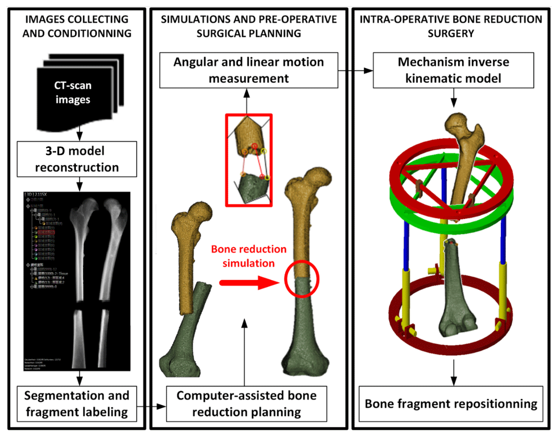
Figure 11Robotic-assisted bone reduction procedure. From pre-operative to intra-operative surgery.
4.2 Results and discussion on the Bone Reduction Surgery Simulation
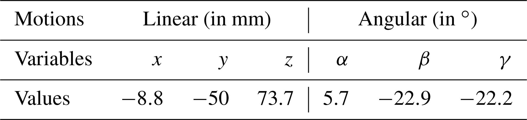
To verify the feasibility of performing the fractured bone reduction using the mechanism introduced in Sect. 2, a simulation has been conducted based on real CT-scan images from a patient showing a fracture of the femur. The images have been provided by the Orthopaedic Department of the Show Chwan Memorial Hospital. After being fully reconstructed in a 3-D environment, the PhysiGuide software has been used to perform a simulated bone reduction. As the femur fragment has been repositioned, the parameters x, y, z, α, β and γ have been numerically measured directly using the software functionalities and they are shown in Table 3.
Table 2Motion variables measured for the repositioning of femur fragments.
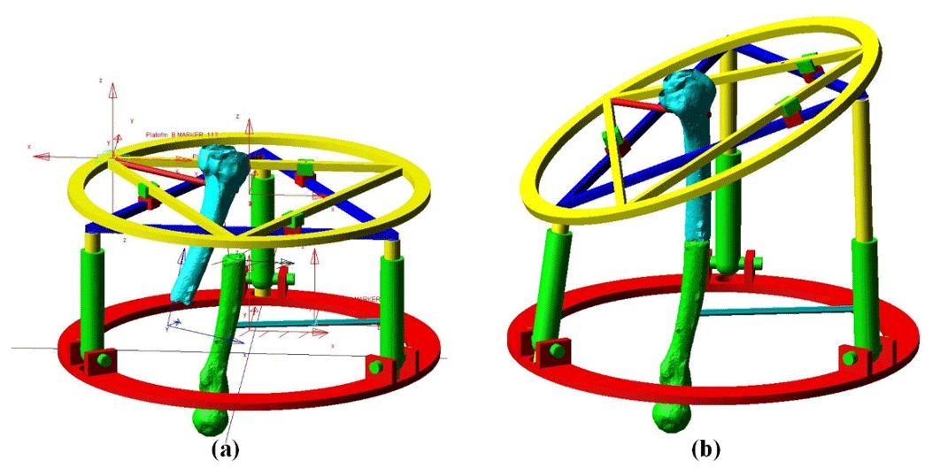
The graphic models of the two bone fragments have been imported in the Adams model of the hybrid mechanism. Their respective positions have been set exactly as measured by PhysiGuide software. One fragment has been attached to the base of the mechanism and the other to its end effector. During the pre-operative planning of a classical bone reduction, the surgeon will estimate the position of the bone fragments. A trajectory will be then roughly defined to move one bone fragment to the other while avoiding collisions. So the robot trajectory in the present case between the initial and final positions illustrated in Fig. 12 cannot be simply defined as a straight line. Several steps must be taken between these initial and final positions. There is no specific method to establish a trajectory. The main concern is to avoid collision between the structures of the bone fragments before the final fracture surface matching, which can be visually performed based on the medical images. Although the surgeon has no concern about numerical coordinates, the use of the kinematic data measured from PhysiGuide allows to verify the suitability of the proposed mechanism for bone reduction surgery.
In the present case, the trajectory has been defined so the initial and final positions of the bone correspond to the position measured by PhyisiGuide before and after the simulated bone reduction. In order to avoid collisions, the different trajectory steps have been set as followed: first, the top moving platform is rotated −22.2∘ about the z axis. The moving platform is then translated along x, y and z axes of with mm, mm, z=43.8 mm. It is then rotated about x axis of α=2.7∘ and about y axis of ∘. After that, a linear translation of the top moving platform in z=30 mm. Finally, rotating the moving platform 1 about x axis with α=3∘ and about y axis with ∘. These motions are represented in Fig. 13. On the other hand, the mechanism input variables that correspond to this trajectory have been calculated and they are displayed in Fig. 14.
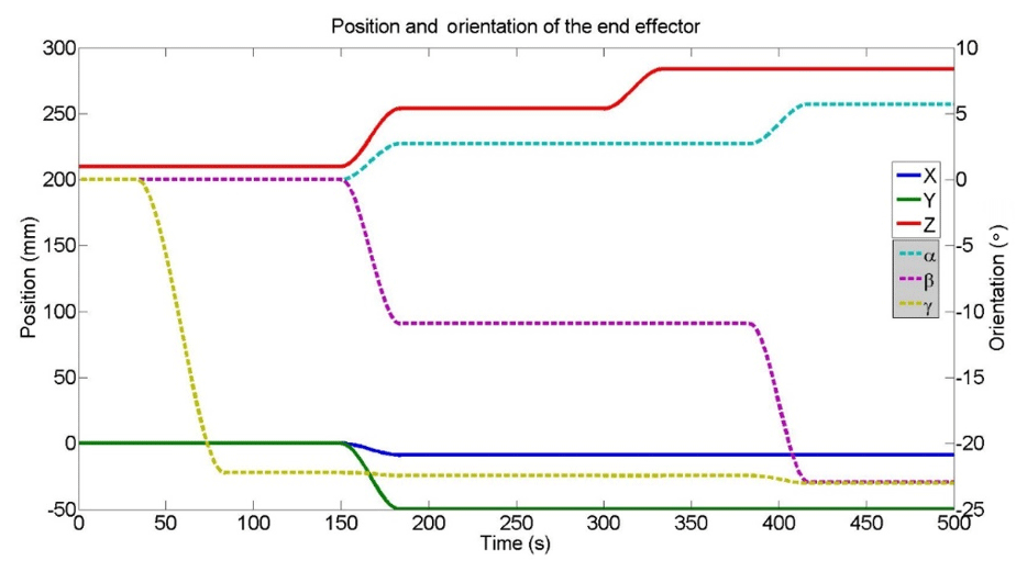
Figure 13Evolution of the end effector coordinated during the simulated bone reduction trajectory.
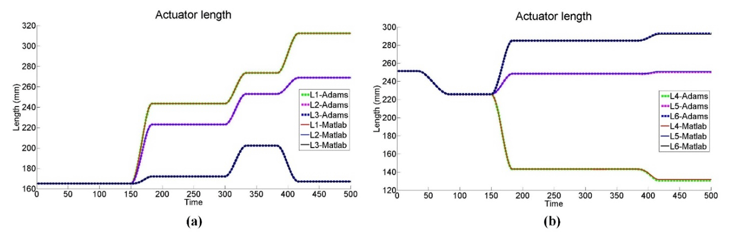
Figure 14Evolution of the mechanism input variables during the simulated bone reduction trajectory.
The different mechanism configurations corresponding to the present case of bone reduction trajectory are illustrated in Fig. 15a to e in xz plane view.
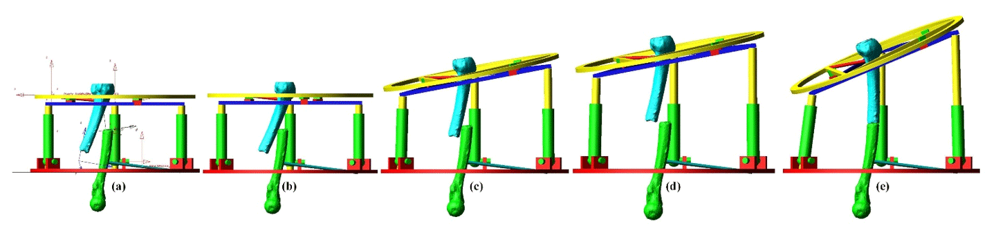
Figure 15Adams view of the mechanism configuration for each step of the bone reduction trajectory in xz plane view (a–e).
In a real intra-operative robotic assisted surgery, the bone fragments would be attached by the means of orthopaedic pins or wires. The mechanism prismatic joints would be actuated until the final configuration is reached and then locked. A prototype can be designed to allow motors to be removed from the robot. The architecture would be secured by the use of irreversible prismatic joints and the remaining frames would act as an external fixation device until the fracture heals. The actual robotic operation can be performed automatically under the supervision of the orthopaedic surgeon who would be able to adjust the manipulation speed or to interrupt the process. Although the robot motion will be performed automatically, the supervising surgeon's control over the system could be offered by a Graphic User Interface that would provide manual minor adjustment on the bone reduction. Such interventions can be enforced by the mean of intra-operative imagery of the patient. As demonstrated above, the proposed hybrid mechanism is capable of providing a complete reduction trajectory as the ranges of motion of all its input variables are respected. On the other hand, it is also noted for this same clinical case, the Stewart manipulator would be in difficulties to perform the bone reduction. Indeed, at the final linear coordinates (, , z=283.7), its angular workspace is insufficient to reach the required angles β and γ and to reposition the bone fragment in the appropriate configuration. This problem could be solved by determining an accurate initial position of the manipulator which would ensure that complete trajectory remain within its workspace. However, there is no guaranty such a position actually exists since its workspace is limited. Also, in the case it would exist, this would require an accurate and delicate registration of the manipulator with the bone fragments. This explains the importance of proposing a mechanism with a workspace and a more adapted kinematic. On the other hand, it can be anticipated that the hybrid mechanism may have smaller stiffness than the Stewart robot. Also, dynamic issues can be predicted due to the presence of floating motors (on the triangular device). But the registration aspects will be far less of a concern since its workspace shows significant improvement.
In the present study, a specific mechanism dedicated to bone reduction surgery has been developed. It is based on a novel mechanical architecture that is adapted to the reduction (i.e. repositioning) of longitudinal broken bones such as femurs. Its kinematics and velocity models have been calculated by taking account of the parasitic motion. Its singularities have been identified and simulation showed that they remain outside for the operation workspace. The mechanism workspace has been compared to the Stewart platform which is considered as a standard in bone reduction surgery. The results show a significant improvement in this aspect. In the surgical procedure, it is planned to obtain its trajectory data from a pre-operative simulation software. Surgical simulations have been performed using medical images of a patient presenting a femur fracture. Using the simulation software, the required trajectory for the bone reduction of the real medical case has been identified and implemented to the mechanism for simulation. It is demonstrated that the manipulator is capable of generating this trajectory and consequently, performing the bone reduction surgery, while the Stewart platform may experience difficulties.
All data used in this paper can be obtained on request from the corresponding author.
SNP and TE worked on the kinematic analysis and simulations of the mechanism and wrote the paper. II and JYL worked on the medical software and provided the kinematic data for the mechanism trajectory.
The authors declare that they have no conflict of interest.
The robotic-assisted bone reduction simulations presented in Sect. 4.2 has been permitted by the use of CT-Scan images of real patients. These materials have been generously provided by the Orthopaedic Department of the Show Chwan Memorial Hospital.
This paper was edited by Anders Eriksson and reviewed by two anonymous referees.
Al-Sayyad, M. J.: Taylor spatial frame in the treatment of pediatric and adolescent tibial shaft fractures, J. Pediatr. Orthoped., 26, 164–170, 2006.
Arakelian, V., Briot, S., Yatsun, S., and Yatsun, A.: A New 3-DoF Planar Parallel Manipulator with Unlimited Rotation Capability, 13th World Congress in Mechanism and Machine Science, 19–25 June 2011, Guanajuato, México, 2011.
Arneson, T. L., Melton, L. J., Lewallen, D. G., and O'Fallon, W. N.: Epidemiology of diaphyseal and distal femoral fractures in Rochester, Minnesota, 1965–1984, Clin. Orthop. Relat. R., 234, 188–194, 1998.
Carretero, J. A., Podhorodeski, R. P., Nahon, M. A., and Gosselin, C. M.: Kinematic Analysis and Optimization of a New Three Degree-of-Freedom Spatial Parallel Manipulator, J. Mech. Design, 122, 17–24, 2000.
Daniali, M., Zsombor-Murray, H. P., and Angeles, P. J.: The kinematics of 3-DoF planar and spherical double-triangular parallel manipulators, Computational Kinematics – Solid Mechanics and Its Applications, 28, 153–164, 1993.
Du, H., Hu, L., Li, C., Wang, T., Zhao, L., Li, Y., Mao, Z., Liu, D., Zhang, L., He, C., Zhang, L., Hou, H., Zhang, L., and Tamg, P.: Advancing computer-assisted orthopaedic surgery using a hexapod device for closed diaphyseal fracture reduction, Int. J. Med. Robot. Comp., 11, 348–359, 2015.
Etemadi-Zanganeh, K. and Angeles, J.: Instantaneous Kinematics of General Hybrid Parallel Manipulators, J. Mech. Design, 117, 581–588, 1995.
Füchtmeier, B., Egersdoerfer, S., Mai, R., Hente, R., Dragoi, D., Monkman, G., and Nerlich, M.: Reduction of femoral shaft fractures in vitro by a new developed reduction robot system “RepoRobo”, Injury, 35, 113–119, 2004.
Graham, A. E., Xie, S. Q., Aw, K. C., Xu, W. L., and Mukherjee, S.: Robotic long bone fracture reduction, in: Medical Robotics, IntechOpen, Vanja Bozovic, p. 526, 2008.
Hu, B. and Yu, J.: Unified solving inverse dynamics of 6-DOF serial–parallel manipulators, Appl. Math. Model., 39, 4715–4732, 2015.
Hunt, K. H.: Structural kinematics of in-parallel-actuated robot-arms, J. Mech. Transm.-T. ASME, 105, 705–712, 1983.
Joung, S., Kamon, H., Liao, H., Iwaki, J., Nakazawa, T., Mitsuishi, M., Nakajima, Y., Koyama, T., Sugano, N., Maeda, Y., Bessho, M., Ohshi, S., Matsumoto, T., Ohinshi, I., and Sakuma, I.: A robot assisted hip fracture reduction with a navigation system, Lect. Notes Comput. SC, 5242, 501–508, 2008.
Kim, Y. H., Inoue, N., and Chao, E. Y.: Kinematic simulation of fracture reduction and bone deformity correction under unilateral external fixation, J. Biomech., 35, 1047–1058, 2002.
Koo, T. K. K. and Mak, A. F. T.: A knowledge-based computer-aided system for closed diaphyseal fracture reduction, Clin. Biomech., 22, 884–893, 2007.
Koo, T. K. K., Chao, E. Y. S., and Mak, A. F. T.: Development and validation of a new approach for computer-aided long bone fracture reduction using unilateral external fixator, J. Biomech., 39, 2104–2112, 2006.
Lee, P. Y., Lai, J. Y., Huang, C. Y., Hu, Y. S., and Feng, C. L.: Computer Assisted Fracture Reduction and Fixation Simulation for Pelvic Fractures, J. Med. Biol. Eng., 34, 368–376, 2014.
Li, B., Li, Y., and Zhao, X.: Kinematics analysis of a novel over-constrained three degree-of-freedom spatial parallel manipulator, Mech. Mach. Theory, 104, 222–233, 2016.
Li, Q., Chen, Z., Chen, Q., Wu, C., and Hu, X.: Parasitic Motion Comparison of 3-PRS Parallel Mechanism with Different Limb Arrangements, Robot. CIM-Int. Manuf., 27, 389–396, 2011.
Li, Q., Xiang, J., Chai, X., and Wu, C.: Singularity of a 3-RPS Parallel Manipulator Using Geometric Algebra, Chin. J. Mech. Eng., 28, 1204–1212, 2015.
Lu, Y., Hu, B., and Yu, J.: Analysis of kinematics/statics and workspace of a 2(SP + SPR + SPU) serial–parallel manipulator, Multibody Syst. Dyn., 18, 619–636, 2009.
Mackie Orthopaedics: Bone Deformity Corection, available at: https://mackie.net.au/procedures/bone-deformity-correction (last access: 9 December 2019), 2016.
Merlet, J. P.: Direct kinematics of planar parallel manipulators, Minneapolis, Minnesota, IEEE Int. Conf. Robot., 4, 3744–3749, 1999.
Moorroft, C. I., Thomas, P. B. M., Ogrodnick, P. J., and Verborg, S. A.: A device for improved reduction of tibial fractures treated with external fixation, P. I. Mech. Eng. H, 214, 449–457, 2000.
Nayak, A., Caro, S., and Wenger, P.: Kinematic analysis of the 3-RPS-3-SPR series–parallel manipulator, Robotica, 37, 1–27, 2018.
Romdhane, L.: Design and analysis of a hybrid serial-parallel manipulator, Mech. Mach. Theory, 34, 1037–1055, 1999.
Seide, K., Wolter, D., and Kortmann, H.-R.: Fracture reduction and deformity correction with the hexapod Ilizarov fixator, Clin. Orthop. R. Res., 363, 186–195, 1999.
Seide, K., Faschingbauer, M., Wenzl, M. E., Weinrich, N., and Juergens, C.: A hexapod robot external fixator for computer assisted fracture reduction and deformity correction, Int. J. Med. Robot. Comp., 1, 64–69, 2004.
Seo, T. W., In, W., and Kim, J.: A new planar 3-DOF parallel mechanism with continuous 360-degree rotational capability, J. Mech. Sci. Technol., 23, 3088–3094, 2009.
Solomin, L. N. (Ed.): The Basic Principles of External Skeletal Fixation Using the Ilizarov and Other Devices, Springer Science & Business Media, Switzerland, 705–803, 2013.
Tang, P., Hu, L., Du, H., Gong, M., and Zhang, L.: Novel 3D hexapod computer-assisted orthopaedic surgery system for closed diaphyseal fracture reduction, Int. J. Med. Robo. Comp., 8, 17–24, 2012.
Taylor, J. C.: Perioperative planning for two- and three-plane deformities, Foot Ankle Clin., 13, 69–121, 2008.
Westphal, R., Gösling, T., Oszwald, M., Bredow, J., Klepzig, D., Winkelbach, S., Hüfner, T., Krettek, C., and Wahl, F.: Robot assisted fracture reduction, Experimental Robotics, 39, 153–163, 2008.
Xie, F., Liu, X. J., and Wang, J.: A 3-DOF parallel manufacturing module and its kinematic optimization, Robot. CIM-Int. Manuf., 28, 334–343, 2012.
Zamani, A. R. and Oyadiji, S. O.: Analytical modelling of Kirschner wires in Ilizarov circular external fixator as pretensioned slender beams, Journal Royal Society Interface, 6, 243–256, 2009.
Zarkandi, S.: Kinematics of a star-triangle planar parallel manipulator, J. Mech. Sci. Technol., 25, 3223–3230, 2011.
Zhang, D., Xu, Y., Ya, J., and Zhao, Y.: Design of a novel 5-DOF hybrid serial-parallel manipulator and theoretical analysis of its parallel part, Robot. CIM-Int. Manuf., 53, 228–239, 2018.
Zheng, X. Z., Bin, H. Z., and Luo, Y. G.: Kinematic analysis of a hybrid serial-parallel manipulator, Int. J. Adv. Manuf. Tech., 23, 925–930, 2004.
Zlatanov, D., Bonev, I. A., and Gosselin, C.: Constraint Singularities of Parallel Mechanisms, Proceeding of the 2002 IEEE International Conference on Robotic and Automation, 1, 496–502, 2002.
Zlowodzki, M., Bhandari, M., Marek, D. J., Cole, P. A., and Kregor, P. J.: Operative treatment of acute distal femur fractures: systematic review of 2 comparative studies and 45 case series (1989 to 2005), J. Orthop. Trauma, 20, 366–371, 2006.