the Creative Commons Attribution 4.0 License.
the Creative Commons Attribution 4.0 License.
 | 04 Dec 2019
Rapid attitude maneuver of the space tether net capture system using active disturbance rejection control
Cheng Wei
Hao Liu
Chunlin Tan
Yongjian Liu
Yang Zhao
The space tether net capture system is a spacecraft system with a mounting tether net for capturing targets. It has the advantages of reusability and the adaptability to capture varying targets with different geometries or flying-motion statuses. However, due to its flexible tether net, the system shows strong nonlinearity, which makes it difficult to achieve the desired control performance for rapid and accurate maneuvering; moreover, this limits the ability of the tether net system to capture fast-moving targets. This paper focused on the maneuver controller design of the space capture system with a large flexible tether net. Firstly, based on the absolute node coordinate method, the dynamic model of the space tether net system is established, which can accurately describe the geometric and material nonlinearities of the space tether net. Then, a two-loop active disturbance rejection control is proposed for the rapid and high-precision maneuvering of the flexible system; meanwhile the second-order extended state observer is designed to estimate and compensate for the tether net vibration disturbance. The simulation validated the proposed control, which could complete the rapid and accurate maneuvering and also compensate for the disturbance caused by the vibration of the flexible tether net.


The increasing amount of space debris poses a great hidden danger to human space activities. Since space junk is mostly non-cooperative, moving or rotating fast and with various shapes, a robotic manipulator employing the rigid contact capture method has difficulty in grasping an unknown target with a fast rotating speed and unknown geometry. For this reason the space tether net capture system has been developed. Shan et al. (2016) reviewed and compared the existing technologies on active space debris capture and removal.
The research on removing debris using tethers is emerging. Williams et al. (2003) presented a new concept for the application of space tethers in planetary exploration and payload transfer. Kawamoto et al. (2006) presented precise numerical simulations for available electric currents, orbital changes, tether stability and deployment dynamics. Tethers are modeled as lumped masses to take into account tether flexibility, and environment models (changes in the plasma density and geomagnetic field and so on) are also considered. Modi et al. (1992) analyzed the performance of the thruster control, tension control and offset control strategies during retrieval of the tether. Misra (2008) researched the dynamics and control of two-body and n-body tethered satellites and various control schemes to stabilize the dynamics during retrieval of the sub-satellite are described. Zhang et al. (2017) developed a brand-new space robot system called the maneuverable tethered space net robot. In addition to the advantages inherited from the tethered space net, extra maneuverability in the tethered space net robot allows for further possibilities for debris capture. Shan et al. (2017) investigated the deployment dynamics of the tether nets, and they found four deployment parameters are critical to the deployment. These are the maximum net area, deployment time, traveling distance and effective period. They modeled the tethered net based on the absolute nodal coordinates formulation (ANCF) to describe the precise dynamics of the tether. Zhai et al. (2009) modeled the tether net system in the orbital frame by applying Lagrange equations, and an integrated control scheme was proposed introducing the thrusters which was effective for in-plane libration damping and enabled the capture net to track an expected trajectory.
The space ejecting flying tether net (Shan et al., 2017) could deploy the flying tether net driven by ejecting mass connected to the corner of the tether net on orbit. Then the net will fly to the target uncontrolled and on its own. It cannot be reused and cannot maintain the configuration during flying, so the flying tether net requires a precise ejecting direction and velocity to capture the target. On the other hand, the space maneuvering flying net (Zhang et al., 2017) could control the tether net configuration by the maneuvering the sub-satellite at the edge corner of the tether net. Although it can maintain or change the net configuration during flight, it can not be reused; moreover, the cost of sub-satellites is high, and the control schema for the whole system consists of a flexible tether net, and multi-satellites are complicated.
The Space-Inflated Tether Net Capture System (SITNCS) could be deployed to an umbrella-like capture structure by inflating the inflatable rods, and then the target could be wrapped and captured by tightening the edge cables. After transferring the target to the desired orbit, SITNCS could loosen the edge cables and deflate the inflatable rods to release the target. SITNCS is controllable, stable and reusable, which makes it also more applicable.
SITNCS operates in four stages shown in Fig. 1: inflation deployment, motorized wrapping, chasing and capturing, and transferring to another orbit. After deployment, the space tether net system has to rapidly approach to the target; the approaching procedure is seriously affected by the large amplitude and low frequency vibration of the inflatable flexible rods and tether net.
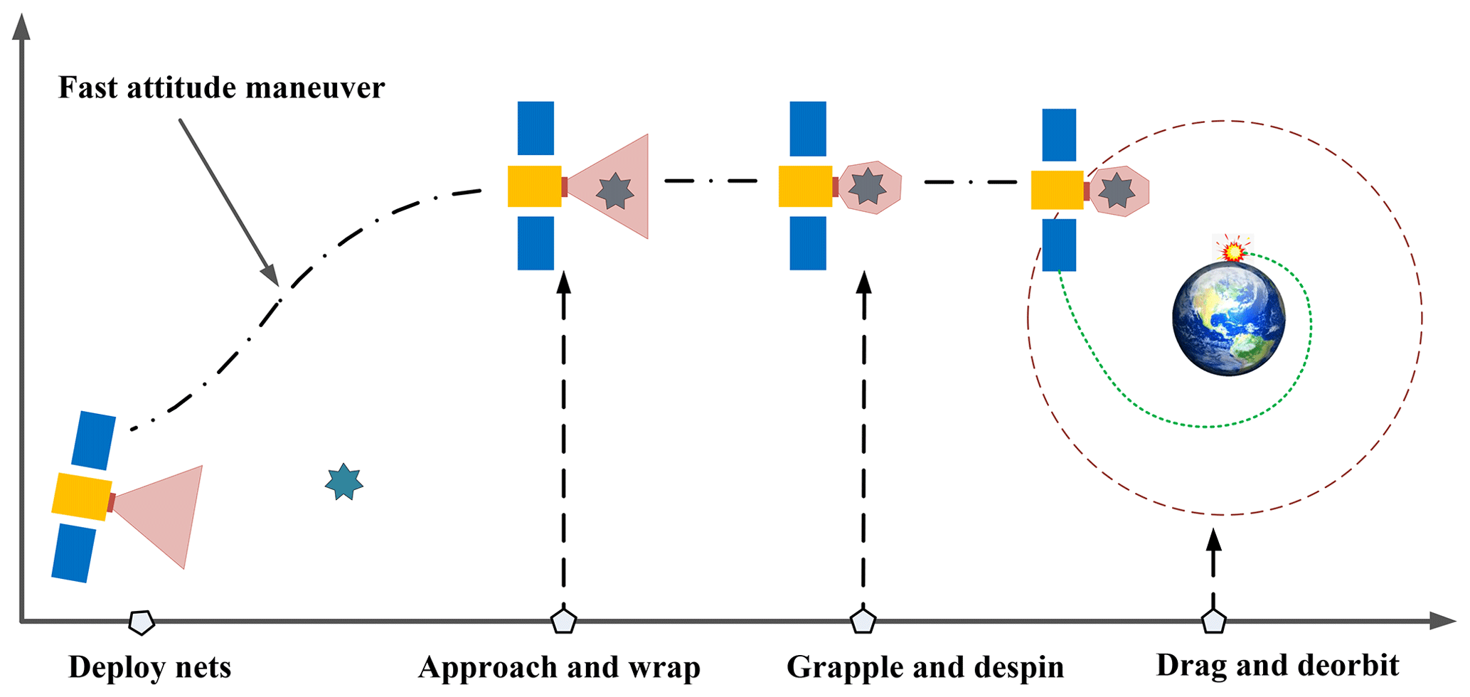
Figure 1The workflow of SITNCS.
At present, the studies on SITNCS are mostly conceptual, such as RETICULAR (Ceruti et al., 2015), REDCROC (Zinner et al., 2011), ROGER (Bischof, 2003) and RemoveDebris (Forshaw et al., 2016). Zinner et al. (2011) presented “Junk Hunter” which could autonomously rendezvous, capture and de-orbit orbital debris, and this system utilizes a deployable, inflatable boom structure supporting a mesh netting. The theoretical research on space flexible-tethered-net capture system is generally about the basic theory of the constructing components rather than the whole system. The inflatable rods is the supporting structure for SITNCS, which is a thin inflatable film structure with a high compression ratio and could maintain stiffness after inflation. Comer and Levy (1963) analyzed the bending stiffness of the inflated beam based on the thin membrane theory, and George (1962) analyzed the supporting rods from shell theory.
The capture tether net is an important part of the space-inflated tether net capture system. At present, the flexible-tether dynamic modeling methods are mainly in two types: a mass-spring model (MS) (Benvenuto et al., 2015) and the absolute nodal coordinate formulation (Gerstmayr and Shabana, 2006). The advantage of the mass-spring method is that it is simple to model and computationally efficient. However, its disadvantage is that the simulation accuracy is low. The ANCF employs the spatial absolute coordinates and its gradient as the generalized coordinates, which is no longer limited as the conventional finite element with the assumption of small deformation and small strains, but it can more effectively describe the large deformation and large rotation of the tethers.
The space-inflated net capture system contains the large-sized inflatable beams and flexible rope nets, and the system exhibits strong nonlinearity and uncertainty. During the attitude maneuvering process, the flexible capturing mechanism vibration makes it difficult for the capture system to achieve fast and accurate attitude maneuver control, thereby limiting the system's ability to capture the target. The traditional PID (proportional–integral–derivative) controller cannot meet the requirements due to its inability to compensate for the disturbances. The active disturbance rejection control (ADRC) could estimate the external disturbance from the vibration of the tether net and compensates for the disturbance in the meantime, which is suitable for high-precision attitude control of the space-inflation rope capture system.
The control for SITNCS makes the spacecraft chase the target since the tether net has large deformable cables which would disturb the attitude of the spacecraft and may cause the spacecraft to fail to capture the fast-moving target. Meanwhile SITNCS will unavoidably undergo the uncertainties and disturbance of the vibrating tether net during capture which would significantly limit the ability of the chasing spacecraft; the traditional PID controller cannot meet the requirements due to its inability to compensate for the disturbances. However, the active disturbance rejection control, which could handle the unknown and time-varying uncertainties and disturbances, is a potential method. The ADRC includes three components, the tracking differentiator (TD), extended state observer (ESO) and nonlinear state error feedback (NLSEF), and has been widely used in industrial applications (Przybyła et al., 2012; Ruan and Li, 2007), which significantly improves the control performance with a good robustness and adaptability. Zhong et al. (2015) proposed a fuzzy ADRC controller for satellite attitude control. Research has been done to solve the attitude control of the spacecraft; Li (2009) and Li et al. (2009) used active disturbance rejection control to get high pointing accuracy and rotation speed for spacecraft with flexible appendages with a small deformation. The control of a large deformable tether net still lacks sufficient research.
Based on the active disturbance rejection control, this paper focuses on the rapid maneuvering of SITNCS with a large deformable tether net. The main contributions are as follows:
-
Based on the absolute node coordinate formulation, the precise dynamic model of SITNCS consists of a spacecraft, inflated boom and flexible tether net, which can accurately present the nonlinear characteristics of the space tether net capture system (Sect. 2).
-
A double-loop active disturbance rejection controller is proposed for the rapid maneuvering of SITNCS, while a transition process is arranged by the TD1 to reduce the vibration of the flexible-tether-net capture system. A second-order divergence observer is employed to estimate and compensate for the disturbance of the space tether system during rapid maneuvering (Sect. 3).
-
Good performance of the proposed method is achieved and validated by simulation, which could control SITNCS for fast and high-precision maneuvering; meanwhile, the vibration disturbance could be effectively suppressed (Sect. 4).
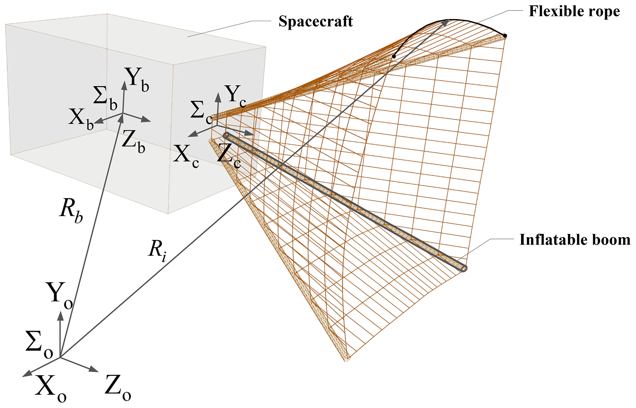
SITNCS consists of a service spacecraft and a capture mechanism with four inflatable rods supporting the trapezoidal prism tether net (Fig. 2). We make the following assumptions to simplify the analysis:
- Assumption 1.
-
The service spacecraft is simplified as a single rigid body, regardless of other appendages other than the flexible-tether-net capture mechanism.
- Assumption 2.
-
The inflatable beam has been inflated and is able to maintain the internal pressure, which could support the tether net forming a capable capturing configuration.
- Assumption 3.
-
There is only a focus on the attitude control of SITNCS, and there is a disregard for the coupling with orbital dynamics.
The reference coordinate system is shown in Fig. 2, where ∑o is the global inertial coordinate system, ∑b is the service spacecraft coordinate system located at the center of the spacecraft, ∑c is the capture mechanism coordinate system and Ri is the vector of material point i in the flexible tether. The following is a dynamic modeling and analysis of SITNCS, which consists of three parts: the inflatable beam, the tether capturing system and the whole system of SITNCS.
2.1 Equivalent model of the inflatable rod
The analysis of conventional inflatable structures is mostly based on the finite element model, but this cannot be easily and efficiently employed for a rigid-flexible-control coupling model of the spacecraft with a large flexible-tether-net system. Therefore, this paper conducts an equivalent modeling analysis based on the ideal-pressure charging theory for inflatable structures.
The bending failure process of the inflatable rod is divided into two parts: the linear load-bearing phase and the buckling failure phase. In the linear load-bearing stage, the deformation of the inflatable beam is small; no wrinkles are formed on the pipe wall; and the inflatable beam exhibits overall buckling. In the buckling failure stage, the inflated beam undergoes large deflection deformation, and the inflatable beam will produce wrinkles in some parts; that is, local buckling and the wrinkle area will no longer participate in the bearing. When the pleated area extends over the entire circumference of the inflatable beam section, the inflatable beam loses its load-carrying capacity (Comer and Levy, 1963).
In this paper, the case is where the inflatable rod is completely inflated and the deformation is small, so the inflatable beam is in the linear load-bearing stage, and the bending stiffness is approximately constant under the allowable air pressure. At this time, the inflatable beam can be equivalent to the Euler–Bernoulli beam.
The bending stiffness of the equivalent beam could be modeled and depends on the section and material properties of the inflated beam. Considering that the bending stiffness of the inflatable beam EiIi and the equivalent beam EeIe are equal, the elastic modulus Ee of the equivalent beam is
where D and d represent the outer diameter and inner diameter of the inflatable beam, respectively, and Ei is the elastic modulus of the inflatable-beam material.
It can be found that the factors affecting the bending behavior of the inflatable beam in the linear load-bearing stage are mainly the material itself and the shape of the section, and the overall buckling is independent of the inflation pressure.
2.2 Dynamic modeling of the tether net using the ANCF
In this section, the dynamic model of the tether has been established based on the ANCF (Gerstmayr and Shabana, 2006), which can describe the large flexibility and large deformation of the space tether net. The configuration and node numbering of the tether net are shown in Fig. 3.
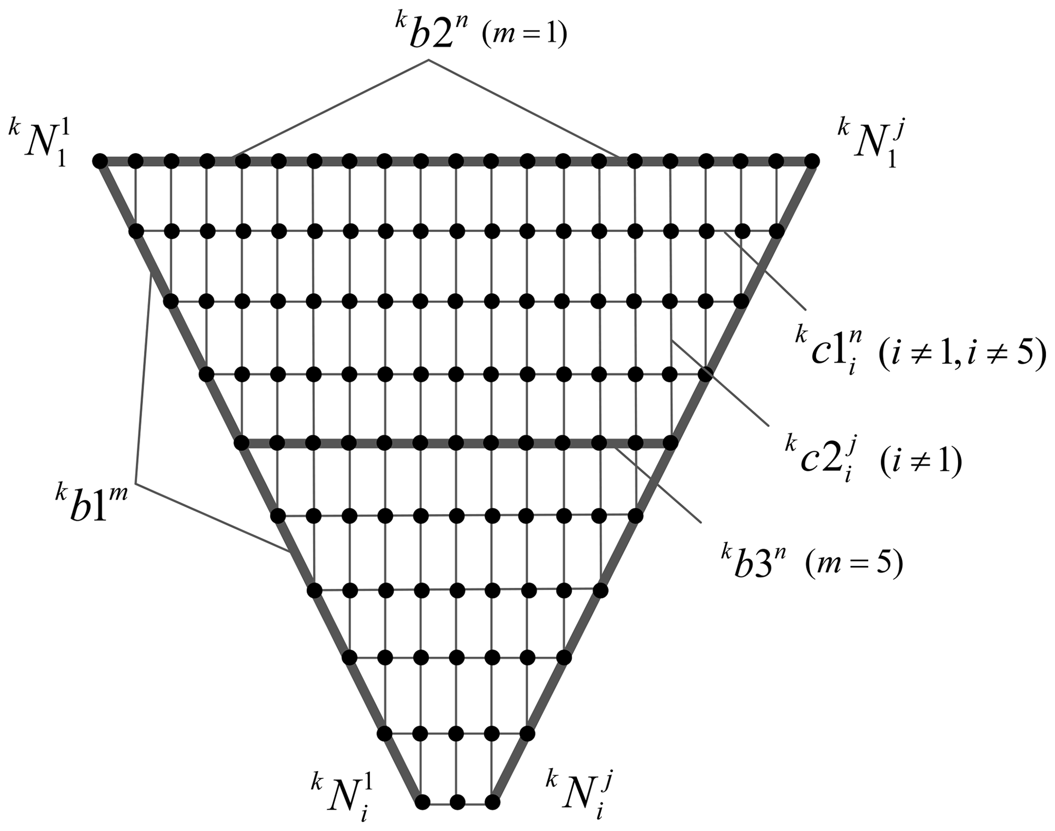
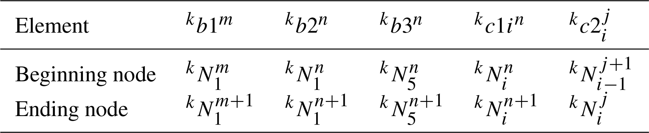
The numbering rule of one side surface is shown in Fig. 4 and Table 1; the nodes are , , , where k is the surface index, i is the row index of kth surface, j is the row index of kth surface and p is the row number (e.g., p=10 in Fig. 4).
The rods consists of the supporting rods and warping rods, where the supporting rods are and the warping rods are kb2n(m=1) and kb3n(m=5), . The horizontal tethers are , where the vertical tethers are .
A flexible cable element considering the axial and bending deformation is obtained on the basis of the theoretical hypothesis of a Euler–Bernoulli beam. Figure 5 shows the undeformed and deformed configurations of the three-dimensional cable element using two nodes.
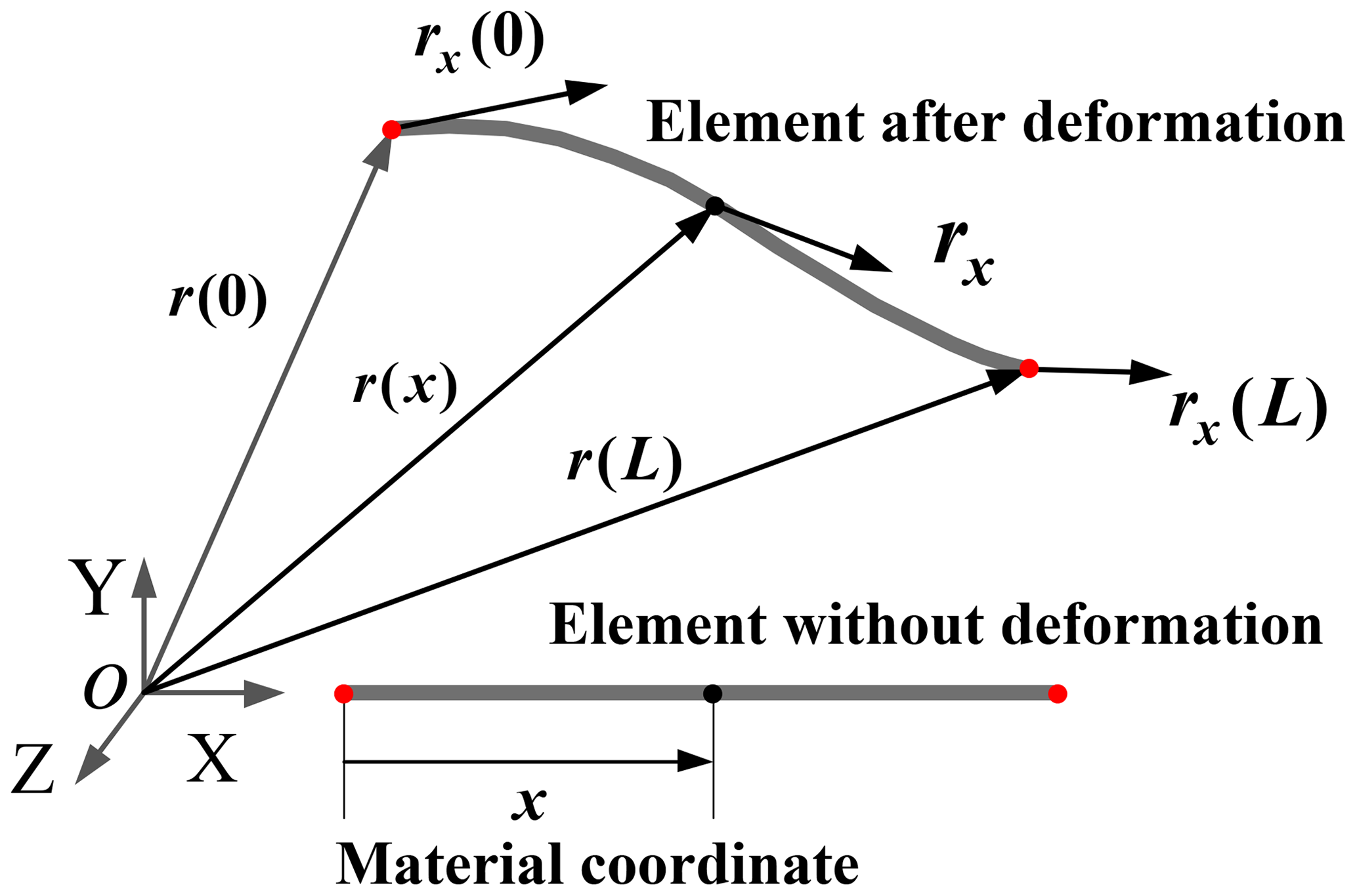
Set the length of the element as L and the generalized coordinates of the cable element to be
where jr and jrx represent the position vector and gradient vector at the end point, respectively.
The position vector of the cable element at a point on the axis of the cable element can be expressed in generalized coordinates as
where S(x) is the shape function of the three-dimensional flexible ANCF cable element.
The kinetic energy of the flexible element can be written as follows:
where ρ and A are the density and cross-sectional area of the cable element, respectively, and is the constant mass matrix of the ANCF cable element.
The elastic energy of the flexible cable element is
where E is the modulus of elasticity, Jκ is the moment of inertia of the flexible cable section, is the axial strain and is the curvature.
The total kinetic energy and strain energy of the system can be written as follows:
Since the dynamics of the element are described by generalized coordinates varying with time, the dynamic equations of the rigid body and flexible body are as follows:
where Qe is the generalized force vector, λ is the Lagrange multiplier, C is the constraint equation, and q and λ are both unknown quantities.
It is derived from the expressions of kinetic energy and strain energy.
The dynamic equation of the flexible cable system can be written as follows:
In this section, a double-loop controller based on the active disturbance rejection control is proposed for SITNCS.
3.1 Spacecraft dynamics
The space-inflated unwinding tether net capture system consists of large-scale flexible inflatable beams and a tether net. The relationship between beam nodes makes the dynamic model very complex and computationally inefficient, which also cannot be directly applied to the design of the control system. The attitude dynamics model considering the rigid-flexible coupling used for controller design (Di Gennaro, 2003) would be expressed as
where J is the moment of the inertia matrix, u is the control torque, d is the external disturbance, δ is the coupling matrix between the spacecraft and the flexible mechanism, η is the flexible modal coordinates, C is the damping matrix, and K is the stiffness matrix. While J0 is the nominal inertia and ΔJ is the unknown inertia, the equation could be derived as
This yields
where .
The attitude dynamic equation of satellite is given by
where θ=[γ ψ ϕ]T is the attitude angle of the satellite, γ is the roll angle, ψ is the pitch angle and ϕ is the yaw angle. R is given by
so the satellite dynamic equation is
3.2 Design of the proposed ADRC control
From the system dynamics in Eq. (15), it is shown that the system is a typical cascade system. Considering that the angular velocity ω and attitude angle θ of spacecraft are measurable, a double-loop controller based on active disturbance rejection control for the spacecraft attitude is proposed.
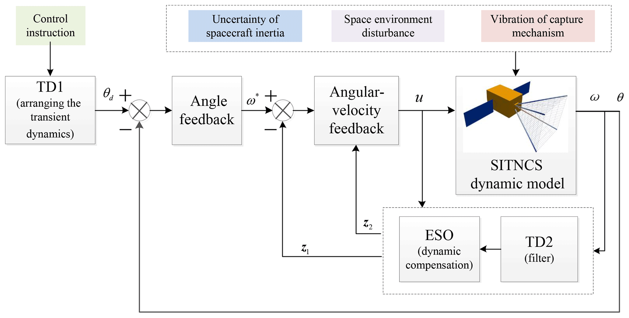
In Fig. 6 the transient procedure is first arranged by the tracking differentiator and then the external-loop feedback controller output virtual angular speed ω∗. Internal-loop feedback is designed by the ADRC. System uncertainties and disturbances are estimated by the extended state observer and compensated for during each sampling period, with the result of achieving a good tracking effect for the angular velocity ω∗. The controller consists of an arrangement of the transient procedure, angle feedback law of the outer loop and disturbance compensation.
3.2.1 Arrangement of the transient procedure
The purpose of arranging the transition process is to reduce the initial control impact in the beginning stage caused by initial errors, which effectively handles the dilemma between overshoot and rapidity. The TD1 is as follows
where v(t) is the input signal, x1 is the estimated value of v, x2 is the derivative of v, h is a simulation step, r is the speed factor and h0 is the filtering factor.
The fhan is defined as follows:
where .
- Remark 1.
-
The two-order steepest nonlinear tracking differentiator is used to avoid the vibration of the tether net system. If h0>h, the TD enables the filtering function.
3.2.2 Angle feedback law of the outer loop
The feedback control law of the outer loop is designed for the angular error of the spacecraft, resulting in the virtual control volume ω∗ in the inner loop. The outer-loop angle feedback control law is
where is a gain matrix for adjusting the speed of tracking the desired value of attitude angle. The function fal is a nonlinear function, and its form is as follows:
where e is the state error , 0<δ.
- Remark 2.
-
Because R(θ) could be calculated, the virtual control variable ω∗ could be compensated for by this ascertained function. Then Eq. (13) could transform into . The nonlinear feedback control law is adopted so that θ will track θd.
3.2.3 Extended state observer design
By using the input and output data of the spacecraft, the ESO could estimate the angular velocity ω and the internal and external disturbances of the system in real time. By expanding the first-order system of Eq. (12) into a two-order system, we can get
A discrete two-order expansion observer is designed as follows:
- Remark 3.
-
The observer states z1 and z2 converge to the state variables ω and d′, respectively. β1 and β2 are observer gains. Because of the limited estimation capability of the ESO, the known part of the nominal model is used in the design process, which could reduce the burden of the ESO and improve its performance and accuracy.
- Remark 4.
-
The resulting observer estimation error system for errors and takes the following form:
If , the errors ξ1 and ξ2 converge to the zeros. The ESO would achieve good performance, which means z1→ω and .
In practical systems, the signals measured by the sensors are unavoidably noisy, which will bring unpredictable disturbances to the controller. The filters need to be designed to extract or restore the original signals from noisy signals. The filter is established by the tracking differentiator.
- Remark 5.
-
The TD2 is used for noise filtering because of its simplicity and ease of use. The original values would not be delayed in predicting the differential signal v2 and prediction step k0.
So the ESO when the system output is polluted by the noise is designed as follows:
3.2.4 Disturbance rejection and compensation
The ESO can estimate the total disturbance value z2 in real time, and then the active disturbance rejection function can be achieved by compensation in the control law. The inner-loop angular velocity feedback control law is
where is the gain matrix.
Considering the above design procedure, the ADRC law for the spacecraft is obtained as follows:
While SITNCS is approaching a fast-moving target, there are many factors which may lead to the system failing to complete the operation. In this section, the PID controller (Wie et al., 1989) is addressed for comparison, and the performance of the ADRC is validated, which could meet the requirements for a rapid attitude maneuver.
4.1 Simulation parameters
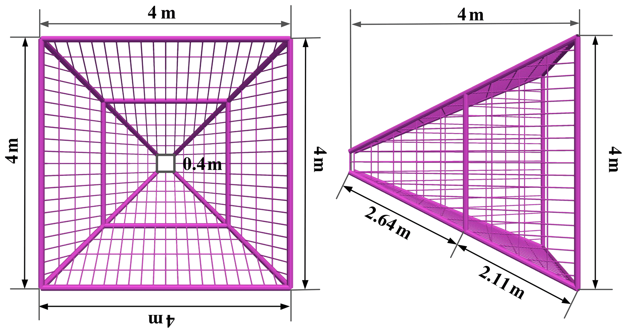
The service spacecraft is assumed to be a single rigid body which is represented by a cuboid with dimensions of 2.5 m × 2.5 m × 4 m. For the capture mechanism, the length of its short side is ld=0.4 m; the length of its long side is lu=4 m; and its height is h=4 m. The constraint between the inflatable rods and tether net is a spherical joint. The constraint between the inflatable booms and the satellite is fixed.
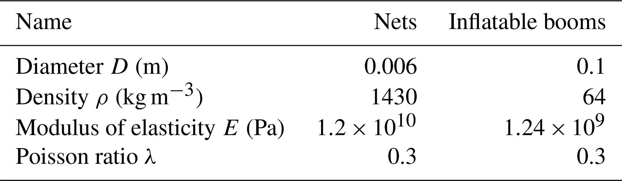
Based on the special requirement of the space environment, the polyimide material is used for the inflatable rods, and the aramid fiber material is chosen for the net. The equivalent parameters of the system with an internal pressure of 25 KPa are listed in Table 2.
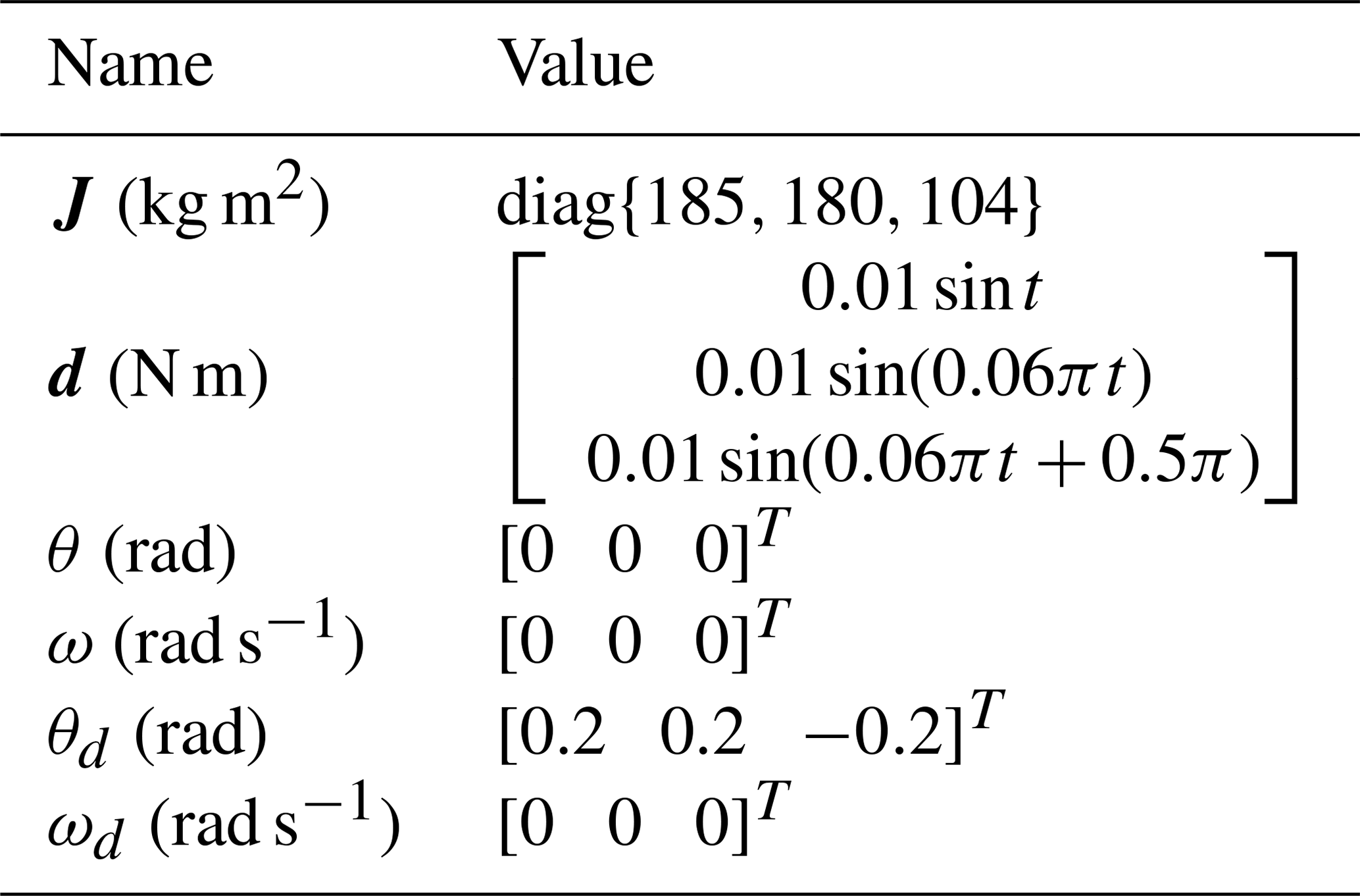
Assuming the moment of inertia of the capture mechanism is unknown, the main parameters of the spacecraft are listed in Table 3, which are the moment of inertia of the spacecraft J, environmental disturbance torque d, initial attitude angle θ, initial angular velocity ω, expected attitude angle θd and expected angular velocity ωd.
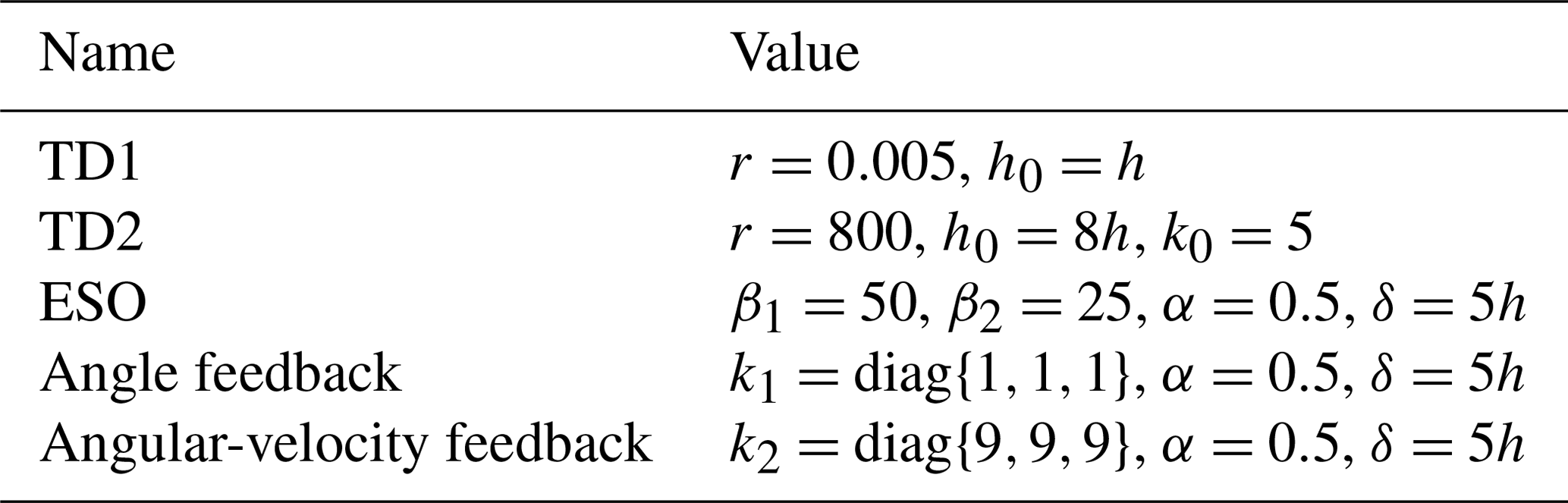
It is reasonable to assume that the signal of the sensor is disturbed by white noise with a peak value of 0.1 % as its the output. The sampling period is h=1 ms. The parameters of the PID controller are and . The parameters of the ADRC are listed in Table 4.
4.2 Attitude control of the spacecraft based on the ADRC
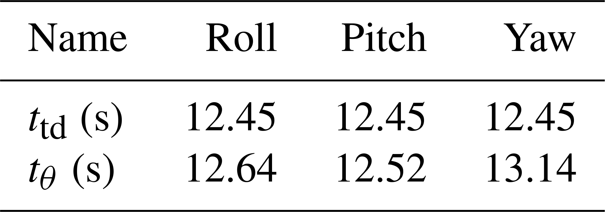
It is assumed that the moment of inertia of the satellite can be accurately obtained and that of the capture mechanism is unknown. ttd is the transition time arranged by the TD1. tθ is defined as the transition time when the attitude error is stable and is between and 10−4 rad s−1. The simulation time is 20 s.
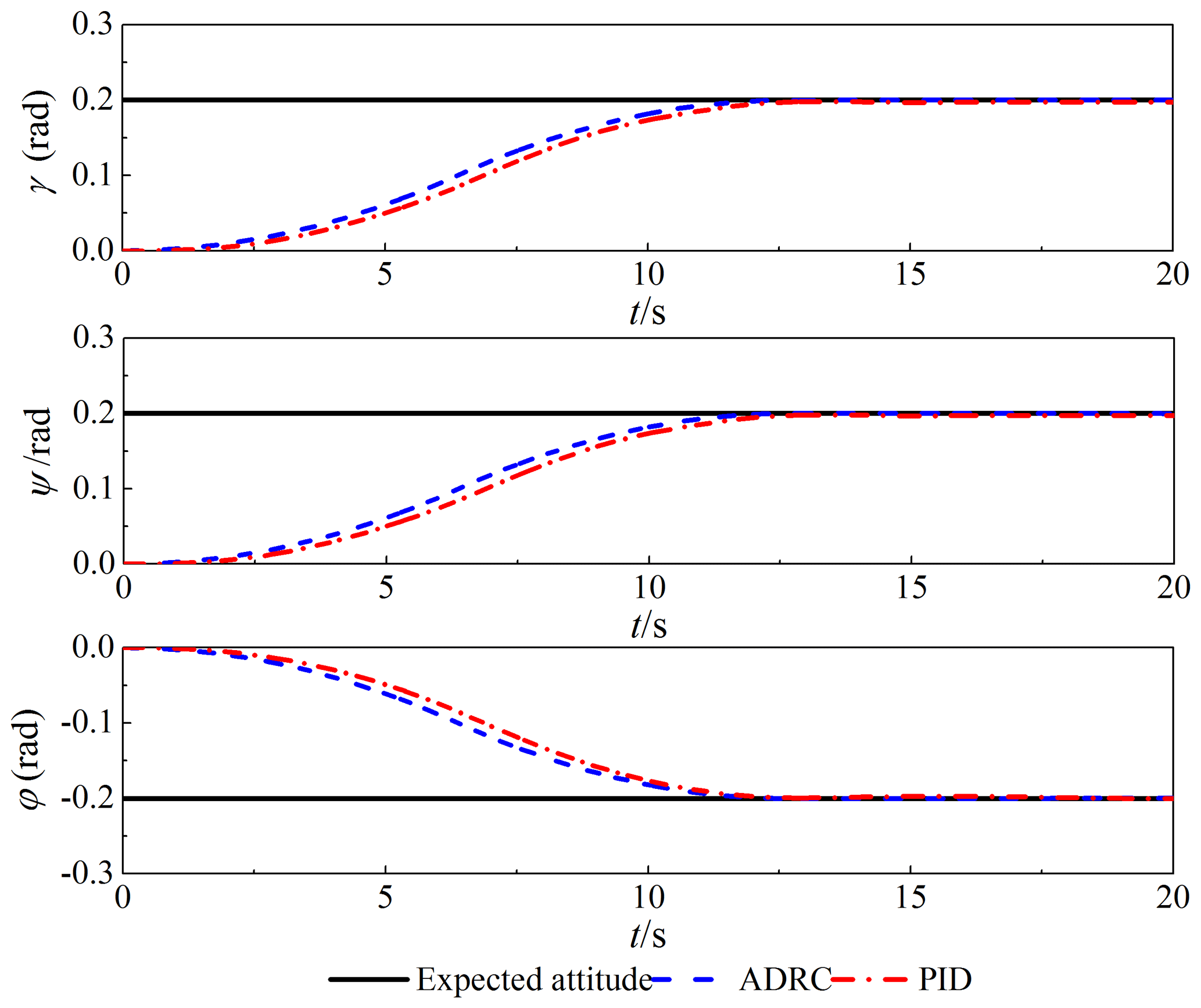
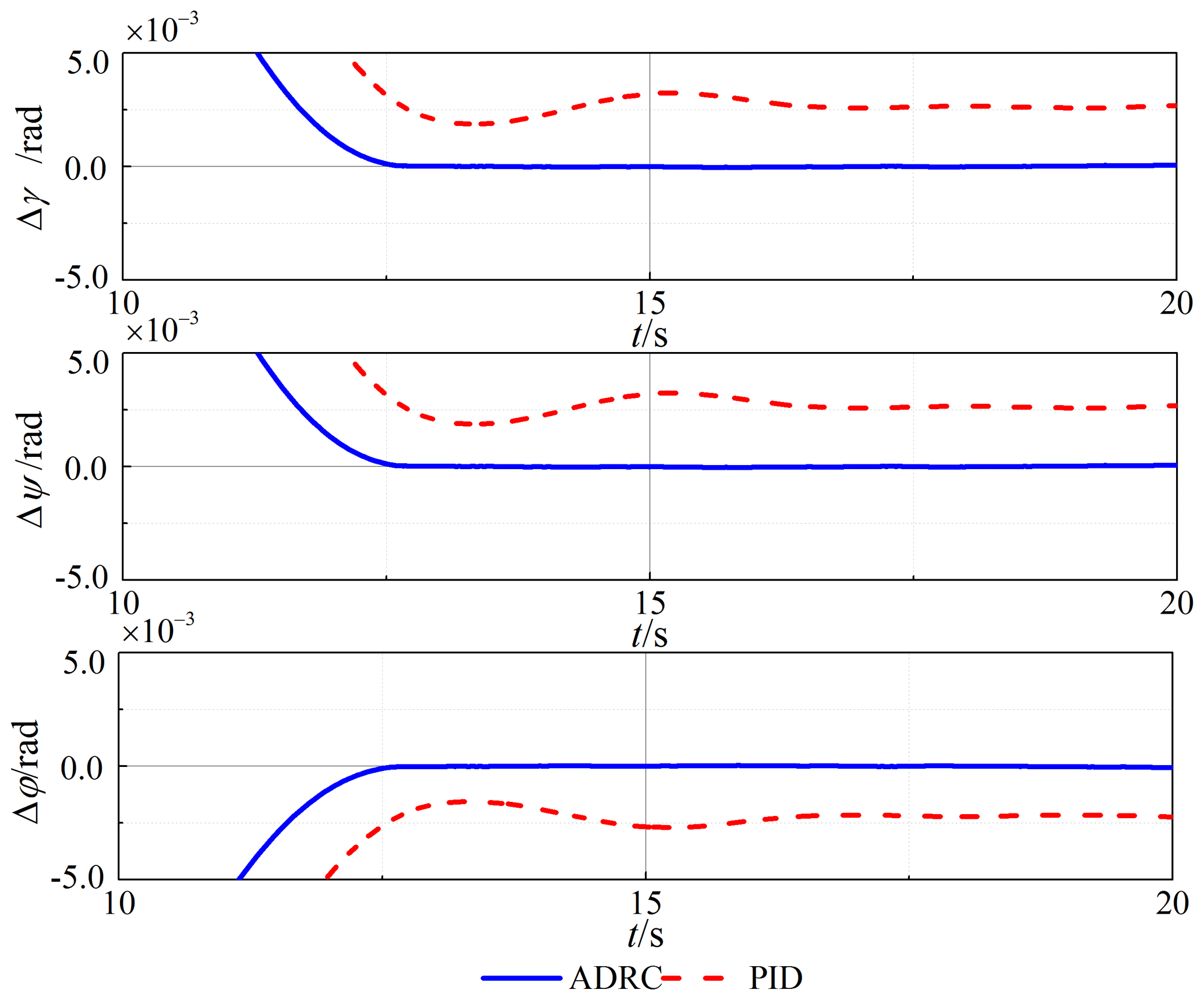
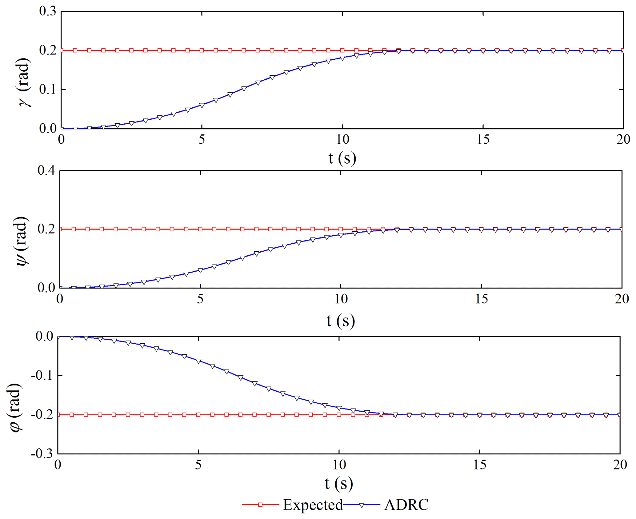
Comparing the two control schemes, the simulation results of the attitude tracking and steady-state error of the spacecraft are shown in Figs. 7 and 8. The ADRC has excellent dynamic and steady-state performance with an error of less than 10−4 rad. The PID controller is greatly affected by the vibration of the flexible tether net; the dynamic tracking has an obvious delay; and the steady-state error is larger; all of this cannot meet the high-precision control requirements. Table 5 shows that the spacecraft can track the desired signal in the transition time arranged by the TD1. The ADRC has high attitude accuracy and robust stability, which are to meet the critical requirements.
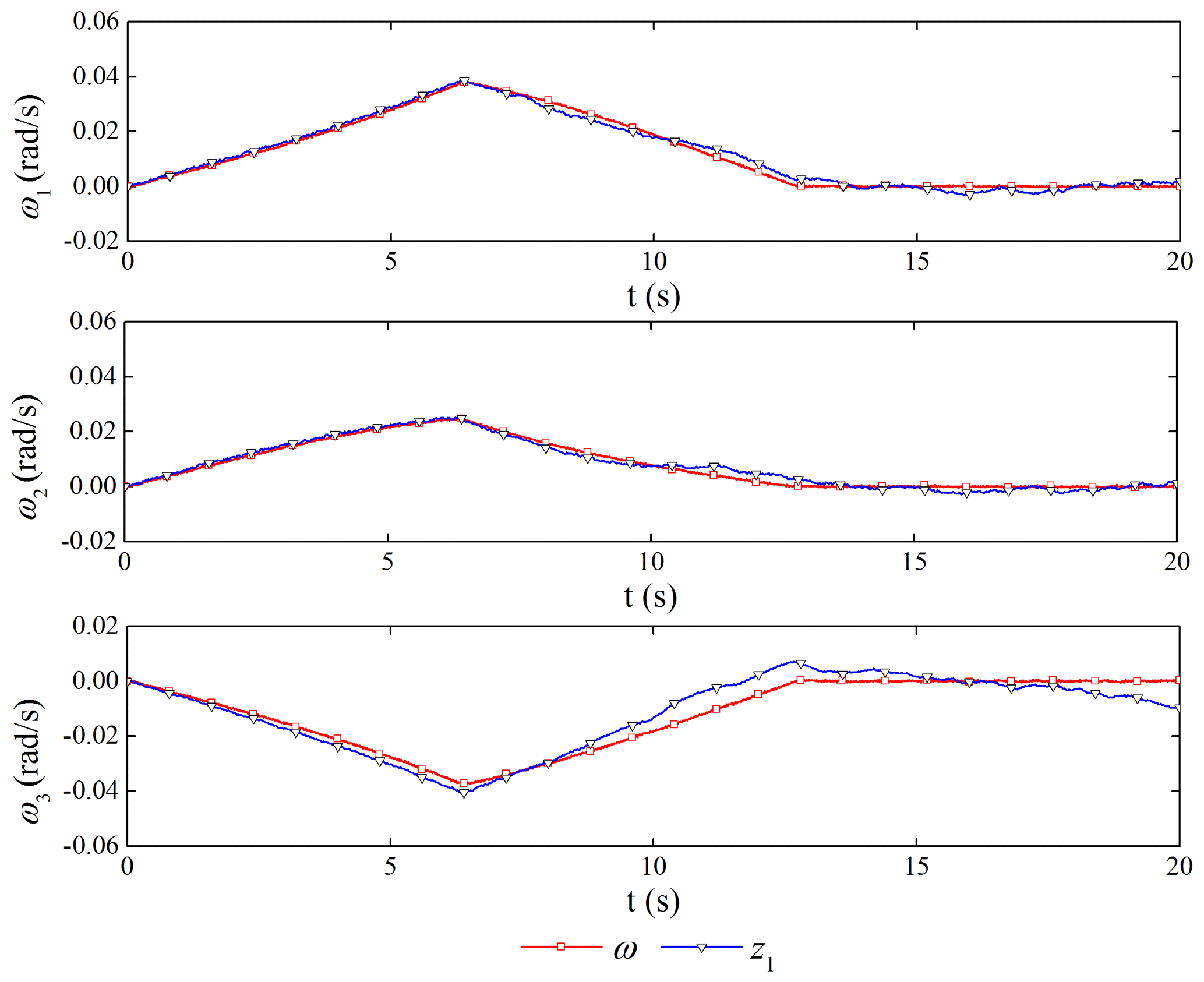
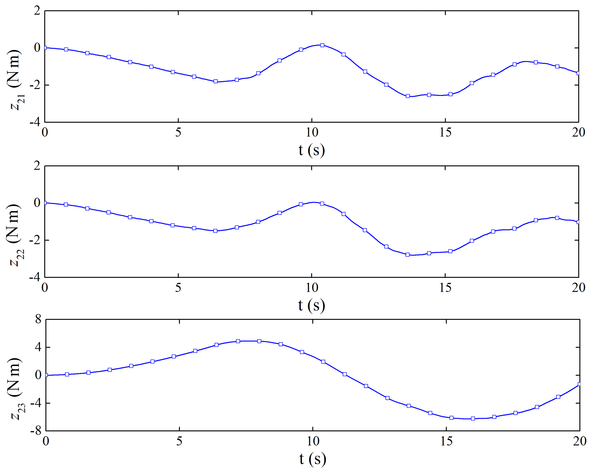
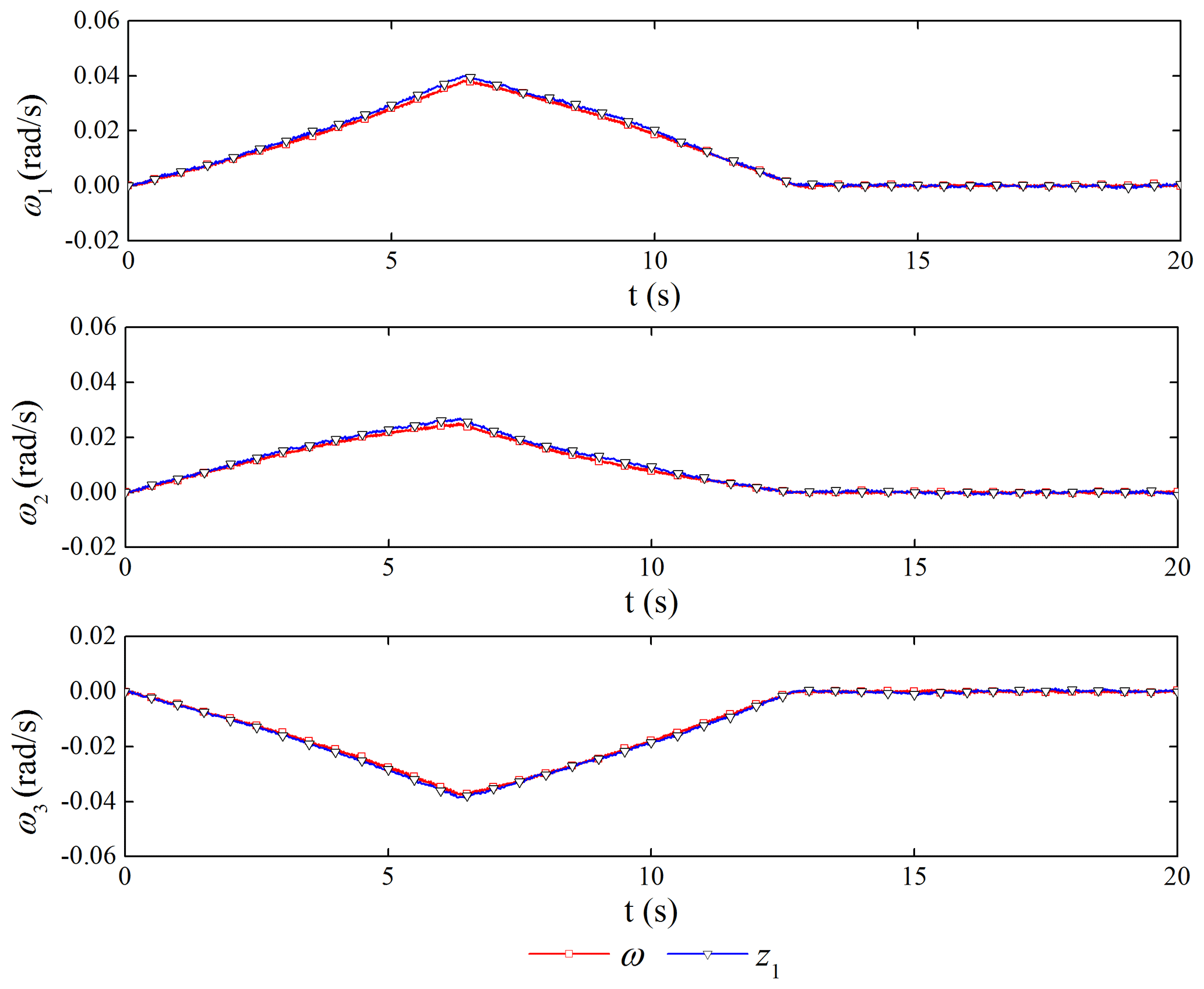
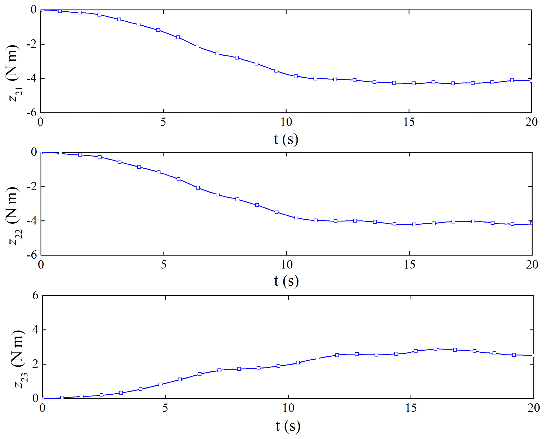
The performance of the ESO is shown in Figs. 9 and 10. The ESO can get the estimated value of the attitude angular velocity of the spacecraft and the disturbance caused by the flexible vibration of the capture mechanism. The maximum amplitude of disturbance can reach 6 N m, which would bring non-negligible disturbance to the satellite platform control.
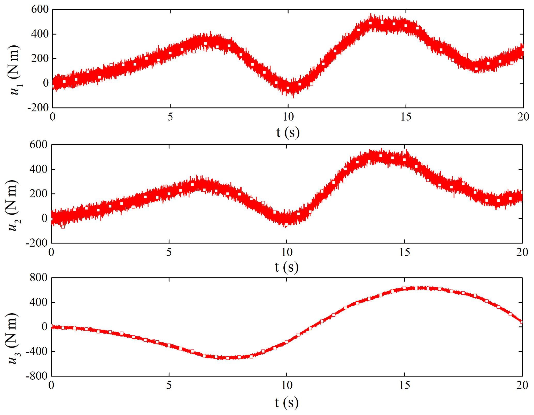
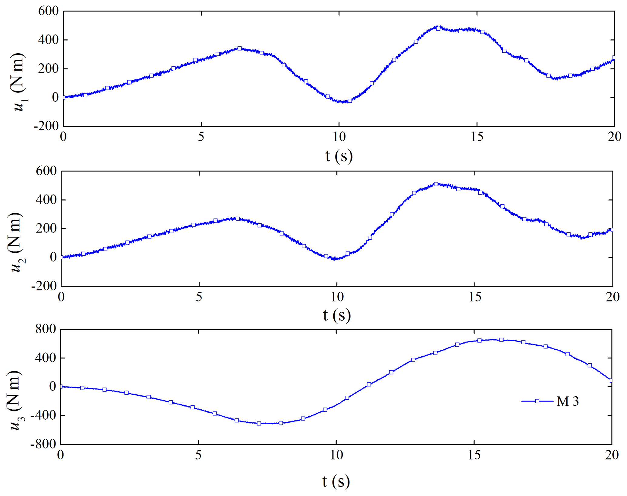
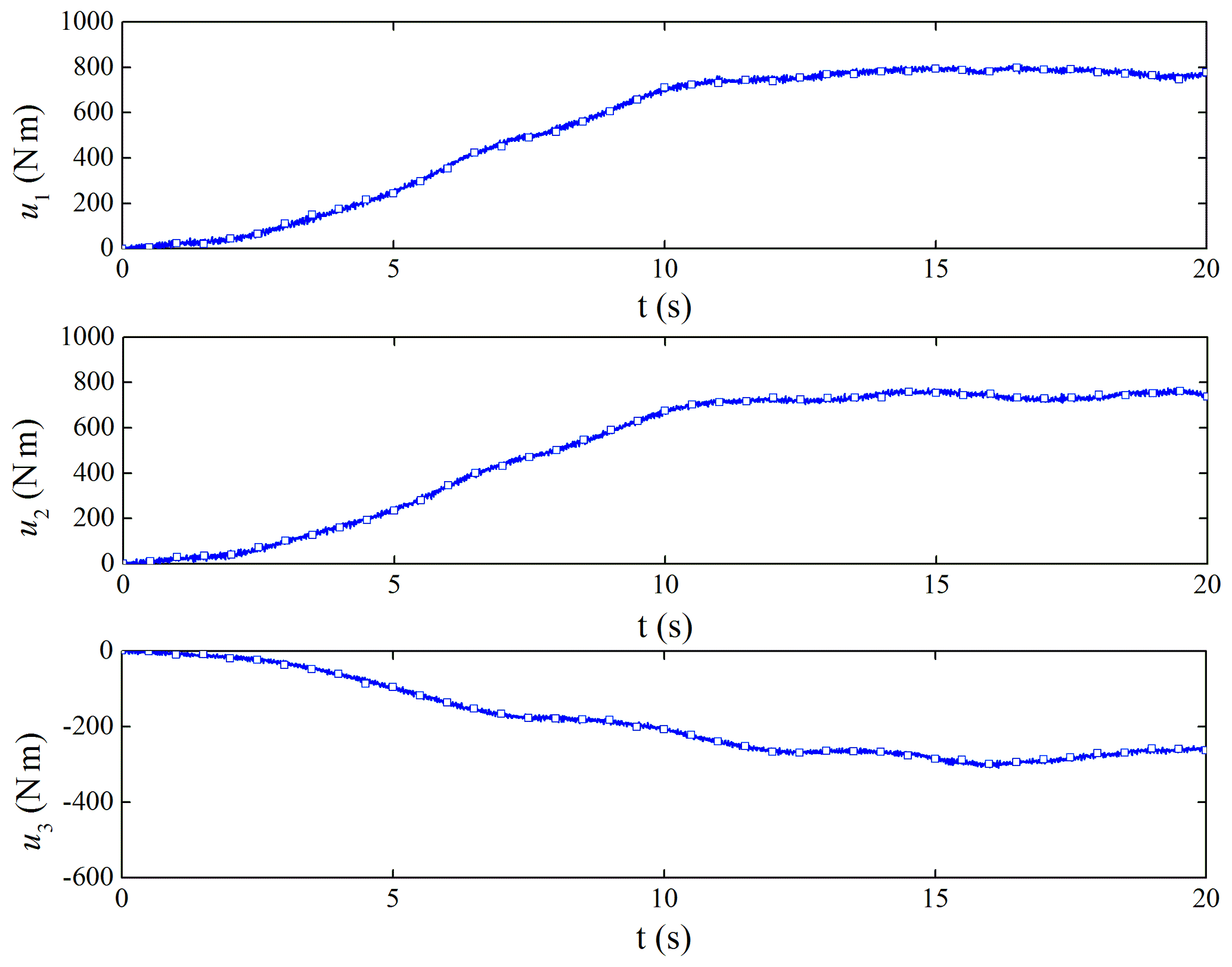
If the TD2 is not used for filtering, we can get the filter performance of the controller. Figure 11 is the original control torque, and Fig. 12 is the control torque after using the filter. It shows that the noise has a great influence on the ADRC. Through filtering, the high-frequency vibration of the torque control is obviously suppressed, which is beneficial to the use of the actuator.
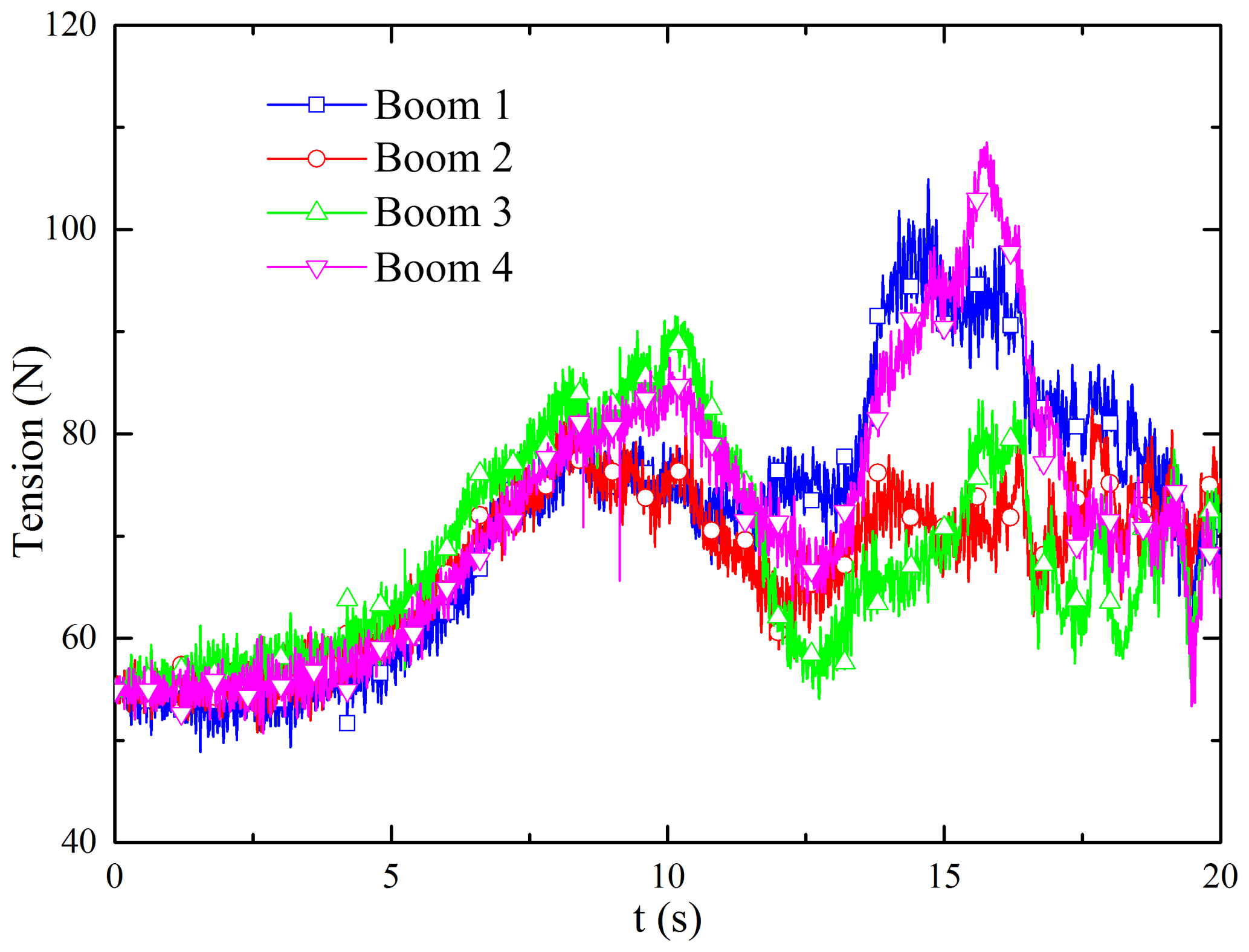
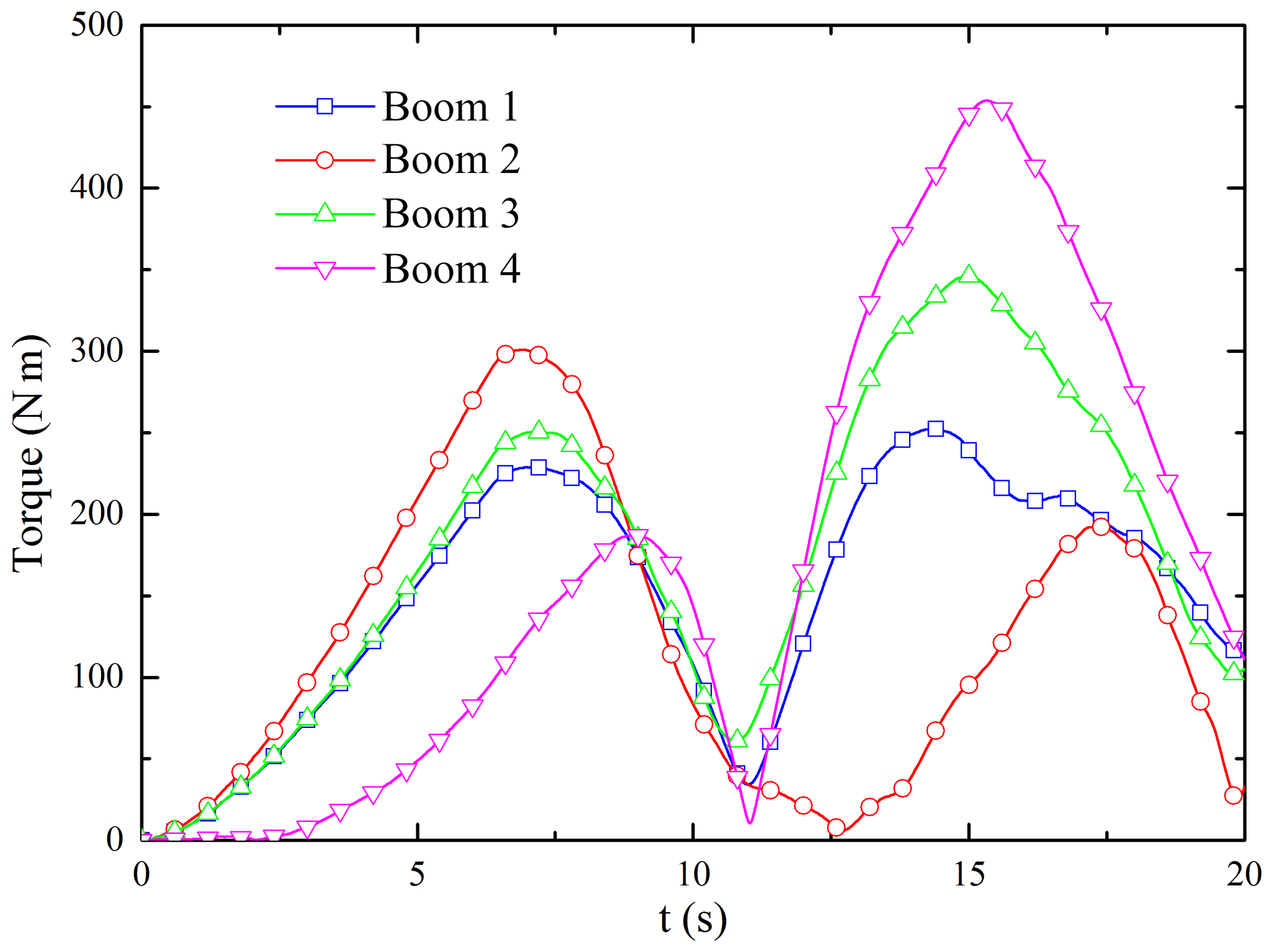
The flexible vibration of the inflatable rods and the tether net is accompanied with the attitude maneuver of the satellite. The largest deformation occurs in the connection point between the inflatable rods and the satellite, resulting in considerable tension and torque. In Figs. 13 and 14, the maximum tension is about 110 N, and the maximum torque is about 450 N m. Therefore, according to the material strength loading limit, it can be asserted whether the stress exceeds the stress limit of the inflatable rod. Otherwise, the applicable way is to increase the transition time to reduce the acceleration.
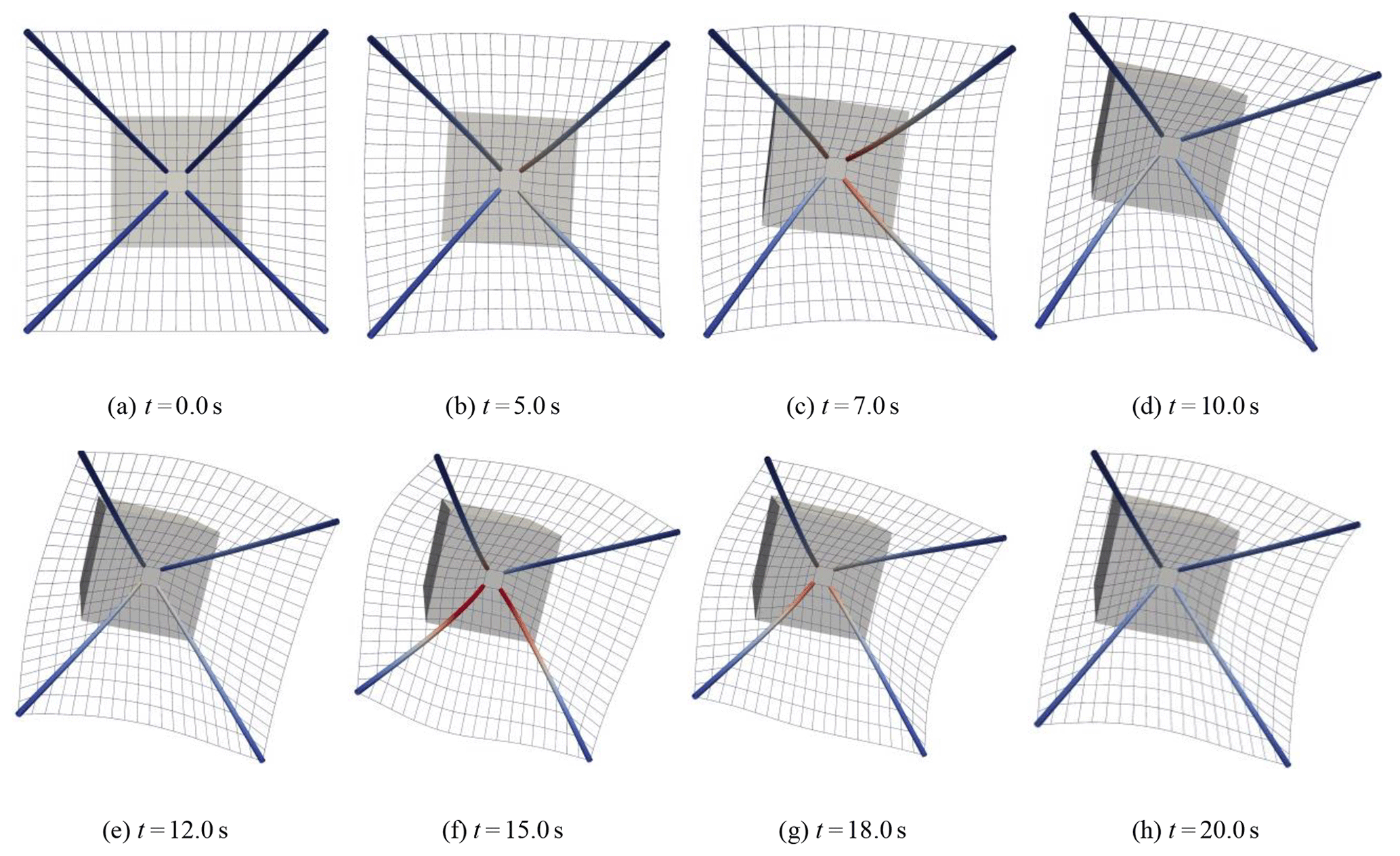
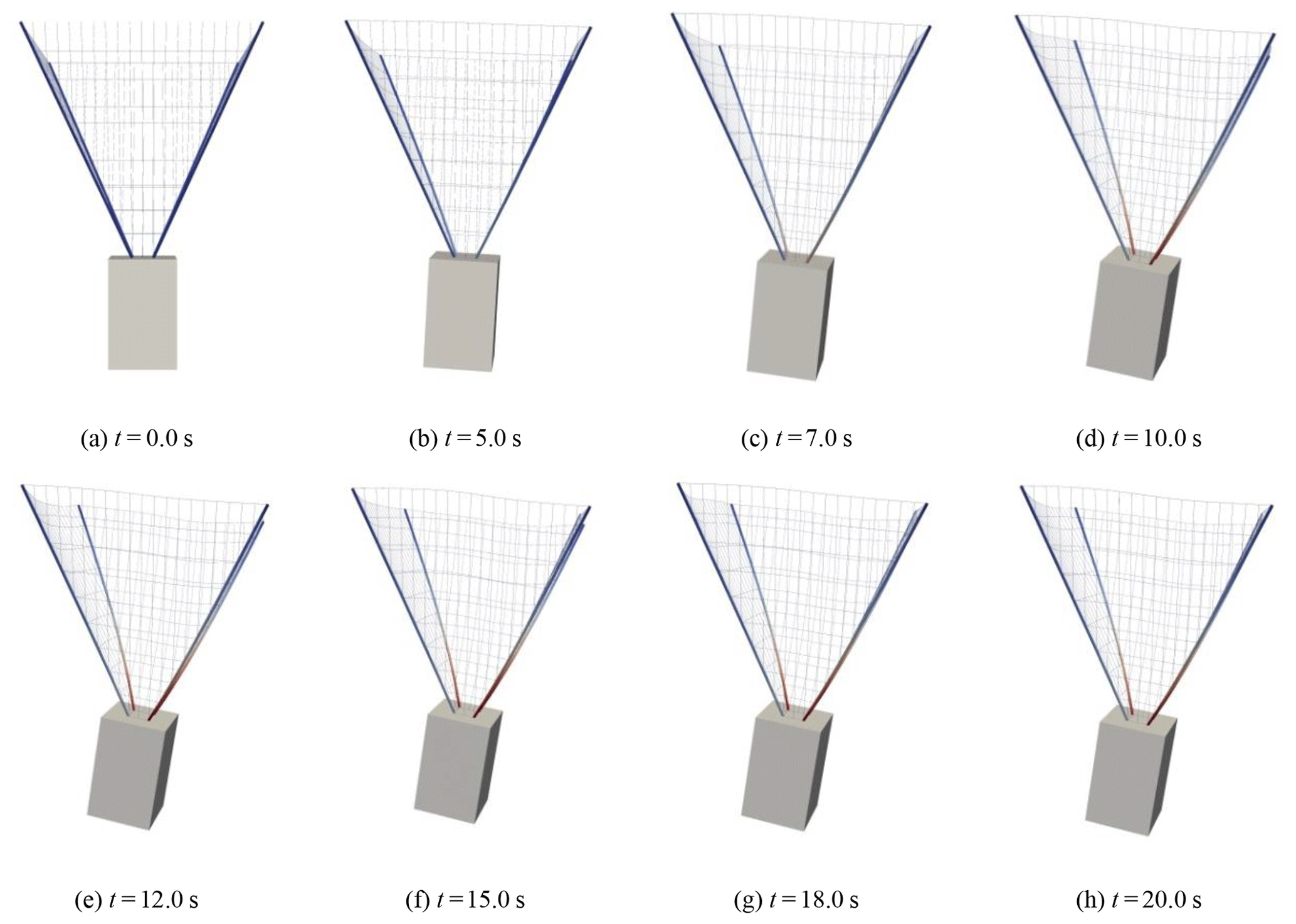
The whole procedure is shown in Fig. 15. It can be seen that the flexible capture mechanism vibrates in terms of the satellite attitude maneuver, but its amplitude is relatively small, which can maintain the configuration and tend to be stable.
4.3 Robustness of a larger SITNCS
In order to adapt to the larger capture target, we can increase the size of the capture mechanism. For the controller, it means having more parameter uncertainties and disturbances. The assumption is that ld=0.8 m, lu=8 m and h=8 m. The simulation time is still 20 s.
Figures 16 and 17 show that the transition time is tθ=[12.66 12.64 12.62]T. When the size of the capture mechanism is increased, the control performance of the system is still excellent. In Figs. 18 and 19, the amplitude of the flexible vibration increases, while the vibration frequency decreases, which improves the estimation effect of the ESO. Therefore, the ADRC has good robustness and disturbance resistance. The simulation (Fig. 20) shows the dynamic changes of the system during the control process.
This paper studies the rapid maneuvering of the space capture system with flexible inflatable rods and a tether net. The two-loop active disturbance rejection control is proposed to complete the rapid and high-precision maneuvering for the space-inflatable tether net capture system; meanwhile the second-order observer is designed to estimate the tether net disturbance, for which could be compensated. The proposed control method could not only achieve the desired performance, but it also could be robust within the disturbance from the flexible-tether-net vibration.
The data cannot be shared publicly at this time as they also form part of an ongoing study. All data included in this study are available upon request by contacting the corresponding author.
CW wrote the whole paper. HL did the simulation and designed the controller. CT modeled the dynamics of the tether net system. YZ drew the figures.
The authors declare that they have no conflict of interest.
The authors would like to acknowledge the support of the Open Fund of the Science and Technology on Space Intelligent Control Laboratory (grant no. 6142208180402) and the National Defense Key Discipline Laboratory of Micro-Spacecraft Technology (grant no. HIT.KLOF.MST.201703).
This research has been supported by the National Natural Science Foundation of China (grant no. 11772102), the Natural Scientific Research Innovation Foundation in HIT (grant no. 30620150071) and the National Defense Key Discipline Laboratory of Micro-Spacecraft Technology (grant no. HIT.KLOF.MST.201703).
This paper was edited by Jinguo Liu and reviewed by Lijie Chen and two anonymous referees.
Benvenuto, R., Salvi, S., and Lavagna, M.: Dynamics Analysis and GNC Design of Flexible Systems for Space Debris Active Removal, Acta Astronaut., 110, 247–265, https://doi.org/10.1016/j.actaastro.2015.01.014, 2015. a
Bischof, B.: Roger – Robotic Geostationary Orbit Restorer, in: 54th International Astronautical Congress of the International Astronautical Federation, the International Academy of Astronautics, and the International Institute of Space Law, American Institute of Aeronautics and Astronautics, Bremen, Germany, https://doi.org/10.2514/6.IAC-03-IAA.5.2.08, 2003. a
Ceruti, A., Pettenuzzo, S., and Tuveri, M.: Conceptual Design and Preliminarily Structural Analysis of Inflatable Basket for an Asteroid Capturing Satellite, Strojniški vestnik, J. Mech. Eng., 61, 341–351, https://doi.org/10.5545/sv-jme.2014.2063, 2015. a
Comer, R. L. and Levy, S.: DEFLECTIONS OF AN INFLATED CIRCULAR-CYLINDRICAL CANTILEVER BEAM, AIAA J., 1, 1652–1655, https://doi.org/10.2514/3.1873, 1963. a, b
Di Gennaro, S.: Output Stabilization of Flexible Spacecraft with Active Vibration Suppression, IEEE T. Aero. Elec. Sys., 39, 747–759, https://doi.org/10.1109/TAES.2003.1238733, 2003. a
Forshaw, J. L., Aglietti, G. S., Navarathinam, N., Kadhem, H., Salmon, T., Pisseloup, A., Joffre, E., Chabot, T., Retat, I., Axthelm, R., Barraclough, S., Ratcliffe, A., Bernal, C., Chaumette, F., Pollini, A., and Steyn, W. H.: RemoveDEBRIS: An in-Orbit Active Debris Removal Demonstration Mission, Acta Astronaut., 127, 448–463, https://doi.org/10.1016/j.actaastro.2016.06.018, 2016. a
George, W. Z.: The Bending Strength of Pressurized Cylinders, J. Aerosp. Sci., 29, 362–363, https://doi.org/10.2514/8.9443, 1962. a
Gerstmayr, J. and Shabana, A. A.: Analysis of Thin Beams and Cables Using the Absolute Nodal Co-Ordinate Formulation, Nonlinear Dynam., 45, 109–130, https://doi.org/10.1007/s11071-006-1856-1, 2006. a, b
Kawamoto, S., Makida, T., Sasaki, F., Okawa, Y., and Nishida, S.-I.: Precise Numerical Simulations of Electrodynamic Tethers for an Active Debris Removal System, Acta Astronaut., 59, 139–148, https://doi.org/10.1016/j.actaastro.2006.02.035, 2006. a
Li, S.: Model and Control of Flexible Multibody Satellite, J. Aerospace Eng., 22, 134–138, https://doi.org/10.1061/(ASCE)0893-1321(2009)22:2(134), 2009. a
Li, S., Yang, X., and Yang, D.: Active Disturbance Rejection Control for High Pointing Accuracy and Rotation Speed, Automatica, 45, 1854–1860, https://doi.org/10.1016/j.automatica.2009.03.029, 2009. a
Misra, A. K.: Dynamics and Control of Tethered Satellite Systems, Acta Astronaut., 63, 1169–1177, https://doi.org/10.1016/j.actaastro.2008.06.020, 2008. a
Modi, V. J., Lakshmanan, P. K., and Misra, A. K.: On the Control of Tethered Satellite Systems, Acta Astronaut., 26, 411–423, https://doi.org/10.1016/0094-5765(92)90070-Y, 1992. a
Przybyła, M., Kordasz, M., Madoński, R., Herman, P., and Sauer, P.: Active Disturbance Rejection Control of a 2DOF Manipulator with Significant Modeling Uncertainty, B. Pol. Acad. Sci.-Tech., 60, 509–520, https://doi.org/10.2478/v10175-012-0064-z, 2012. a
Ruan, J. and Li, Y.: ADRC Based Ship Course Controller Design and Simulations, in: 2007 IEEE International Conference on Automation and Logistics, 2731–2735, IEEE, Jinan, China, https://doi.org/10.1109/ICAL.2007.4339044, 2007. a
Shan, M., Guo, J., and Gill, E.: Review and Comparison of Active Space Debris Capturing and Removal Methods, Prog. Aerosp. Sci., 80, 18–32, https://doi.org/10.1016/j.paerosci.2015.11.001, 2016. a
Shan, M., Guo, J., and Gill, E.: Deployment Dynamics of Tethered-Net for Space Debris Removal, Acta Astronaut., 132, 293–302, https://doi.org/10.1016/j.actaastro.2017.01.001, 2017. a, b
Wie, B., Weiss, H., and Arapostathis, A.: Quarternion Feedback Regulator for Spacecraft Eigenaxis Rotations, J. Guid. Control Dynam., 12, 375–380, https://doi.org/10.2514/3.20418, 1989. a
Williams, P., Blanksby, C., and Trivailo, P.: Tethered Planetary Capture: Controlled Maneuvers, Acta Astronaut., 53, 681–708, https://doi.org/10.1016/S0094-5765(03)80029-2, 2003. a
Zhai, G., Qiu, Y., Liang, B., and Li, C.: On-Orbit Capture with Flexible Tether–Net System, Acta Astronaut., 65, 613–623, https://doi.org/10.1016/j.actaastro.2009.03.011, 2009. a
Zhang, F., Huang, P., Meng, Z., Zhang, Y., and Liu, Z.: Dynamics Analysis and Controller Design for Maneuverable Tethered Space Net Robot, J. Guid. Control Dynam., 40, 2828–2843, https://doi.org/10.2514/1.G002656, 2017. a, b
Zhong, C., Guo, Y., and Wang, L.: Fuzzy Active Disturbance Rejection Attitude Control of Spacecraft with Unknown Disturbance and Parametric Uncertainty, Int. J. Control Autom., 8, 233–242, https://doi.org/10.14257/ijca.2015.8.8.24, 2015. a
Zinner, N., Williamson, A., Brenner, K., Curran, J., Isaak, A., Knoch, M., Leppek, A., and Lestishen, J.: Junk Hunter: Autonomous Rendezvous, Capture, and De-Orbit of Orbital Debris, in: AIAA SPACE 2011 Conference & Exposition, American Institute of Aeronautics and Astronautics, Long Beach, California, https://doi.org/10.2514/6.2011-7292, 2011. a, b