the Creative Commons Attribution 4.0 License.
the Creative Commons Attribution 4.0 License.
 | 07 Oct 2019
Dimensionless design approach to translating flat faced follower mechanism with two-circular-arc cam
In this study, a dimensionless design approach was presented for translating flat-faced follower mechanism with two-circular-arc cam. Instead of second arc radius (r2), maximum follower lift (smax) and angle of the cam rotation angle (2θmax) variables from the cam profile design parameters were made dimensionless using r2∕r (=λ), smax∕r (=ψ) and θmax∕π (=μ) respectively. Equations for cam profile and follower movement were derived and graphics were obtained depending on the dimensionless parameters. λ and ψ should be in the range [0.0, 1.0], but μ should be in the range [0.0, 0.5]. λ and ψ were changed in the range [0.10, 0.90] and μ in the [0.25, 0.45] range and λ, ψ and μ values were determined for the cam profile. Maximum velocity (vmax), maximum absolute acceleration (amax) and average follower lift (save) changes, which are one of the critical characteristics of follower, were examined for possible cam profiles according to the change of λ, ψ and μ. As a result, vmax and save decreased when μ was increased, vmax and save increased and amax decreased when ψ was increased, amax and save increased when λ was increased.


The cam mechanisms are often used in a number of mechanical systems to deliver a desired movement to a machine element by means of surface contact (Arabaci et al., 2014). Cam mechanisms are widely used in the automotive industry. Cam mechanisms are used to provide the movement of the valves in internal combustion engines according to a specified profile (Hsieh, 2010; Chen, 1977). Circular arc cam is frequently preferred in cam mechanisms. Since the profiles of circular arc cams are obtained with two or more circular arcs, they can be easily made with basic geometric principles (Chen, 1977). In addition to the design of circular arc cams, the production is easy and economical (Lanni et al., 1999). Circular arc cams design uses two or three circular arcs (Grohe and Russ, 2010). Although there are cam designs using four and more circular arcs, it is not preferred because of the complexity in the mathematical model (Grohe and Russ, 2010; Xiaoyi, 1999). Circular arc cams can be used with flat-faced or roller follower mechanisms. Çınar and Uyumaz (2014) have designed a cam with a flat-faced follower for a homogeneous charged compression-ignition gasoline engine and compared the 5th degree spline and two circular arc functions in the cam profile. It was emphasized that the two circular arc cam is more suitable for the cam profile to be operated with flat-faced follower. Ceccarelli et al. (2005) examined the design and characterization problems of circular-arc cams. Lin et al. (2017) discussed a new method based on the nonlinear least squares for the investigation of discontinuity or non-smoothness that may occur at the arc joining points of the circular arc cams. Lanni et al. (2002) tried to obtain the most suitable cam profile by designing three circular arc cam profile by analytical method. Hsieh (2010) derived the design equations by forming a general geometric model of three circular arc cam profiles. Bižić et al. (2013) discussed a simple methodology for modeling the profile of two circular arc cams where homogeneous coordinate transformation was applied, and analytical expressions were derived for all design parameters. Kim and Ahn (2007) discussed a method using Bazier curves for the design of a circular arc cam.
In the literature, geometric or analytical methods are used for design parameters of circular arc cams. With these methods, it is discussed to obtain the most suitable cam profile of the desired size. In addition, these studies generally focus on limited design and optimization for real cam profiles based on the design parameters. It is also very difficult to find a systematic methodology in the design of circular arc cams in the literature. In this study, the dimensionless design parameters for the two circular arc cam profiles with translating flat follower mechanism are presented. In the proposed model cam height (or lift), base circle radius and cam working (or rotation) angle are considered as the main parameters. Other parameters such as radii and angles (or lengths) of circular arcs are non-dimensioned by using main parameters. Then the effects of all design parameters are discussed in detail.
2.1 Terminology of two-circular arc cam
Apart from the center of the basic circle in the two circular arc cams there are also separate centers of circular springs. The first arc center forming the opening and closing ramps (or flanks) is mostly outside the cam profile. The second arc center that forms the nose is always within the cam profile (Fig. 1).
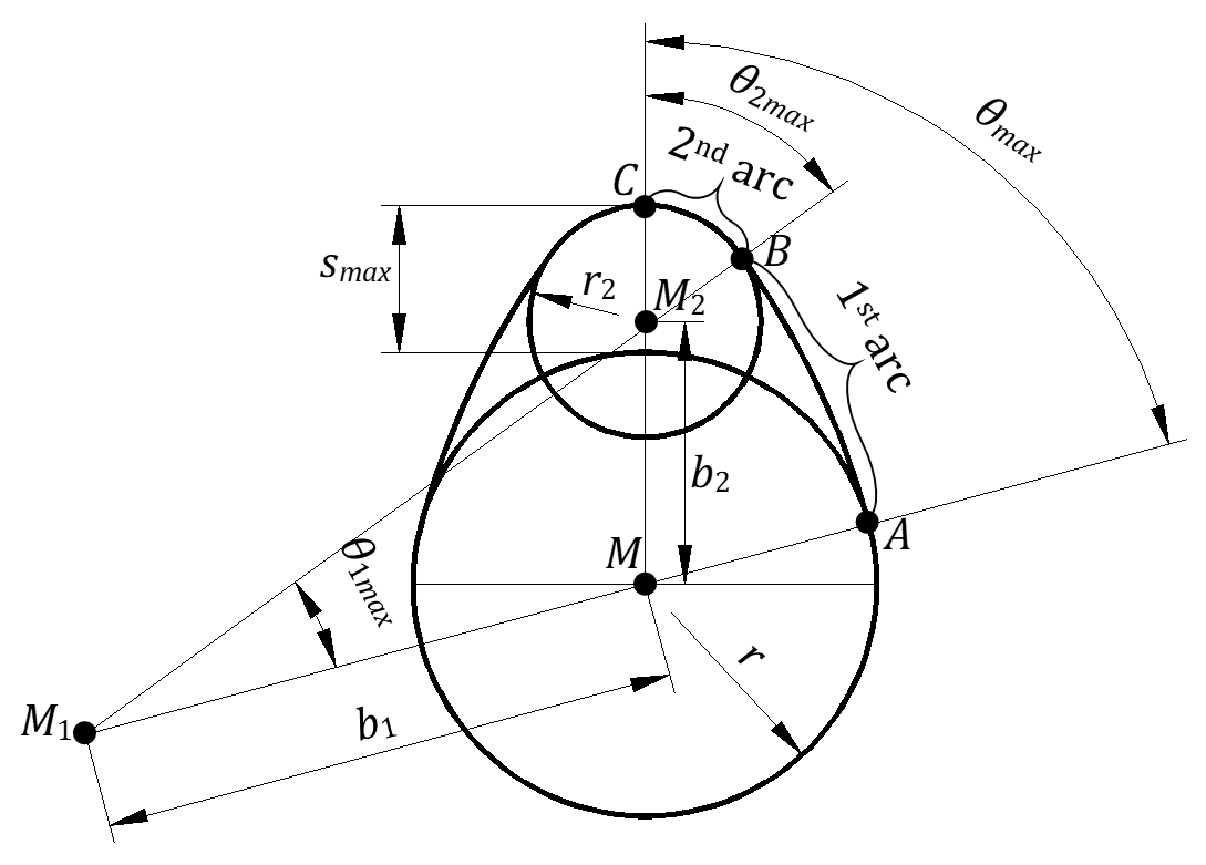
Figure 1Terminology of two-circular arc cam (Grohe and Russ, 2010).
In Fig. 1, M, M1 and M2 are the centers of the circles. smax is maximum follower lift or maximum cam height. In the cam profile, θ1,max and θ2,max refer to the first and second arc angles, respectively. b1 and b2 are the distances of the arc centers to the center of the base circle. r is the radius of the base circle, r1 and r2 are the radii of the arcs. θmax is half the angle of the cam rotation angle.
2.2 Dimensionless design variables for two-circular arc cam
For the dimensionless design of the two circular arc cam, the following new variables can be defined.
Here it should be ψ>λ. Accordingly, b1 and b2 are expressed as b1∕r and b2∕r as follows.
The angular relationship between θmax, θ1,max and θ2,max must also be known for the cam design.
All of the above equations are based on simple geometric principles. To obtain the cam profile, these equations are sufficient and the cam profile determines the movement characteristics of the follower. Figures 2 and 3 show the movement of translating flat-faced follower, which works with the two circle arc cam.
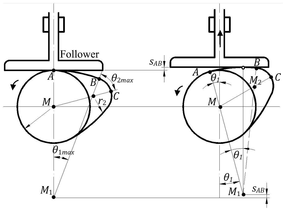
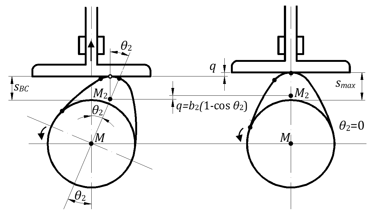
According to Figs. 2 and 3, the movement of the follower in the arc-AB and arc-BC is expressed respectively as follows.
At the beginning (A), the follower velocity is zero and reaches the maximum velocity at the end of the closing ramp (B) according to the cam profile (Fig. 2). In this process, the acceleration is always positive and the cam and the follower are in constant contact. When the follower reaches the maximum velocity (B), the acceleration is negative in the process up to the top-point (C) where the velocity is zero (Fig. 3). In the case where the acceleration is negative, the inertial forces of the moving parts force these parts to remove from the cam. The follower spring tries to prevent these parts from being removed from the cam. A negative maximum acceleration occurs at the point-C. The maximum velocity and the negative maximum acceleration of the follower can be calculated with the following equations (Arabaci et al., 2014; Grohe and Russ, 2010).
In order for vmax and −amax to be dimensionless, Eqs. (14) and (15) have been rearranged:
If the follower could be opened up to the maximum cam height without being dependent on time, the average follower movement would be equal to the maximum cam height. There are boundary conditions such as, but not limited to, the maximum velocity and maximum acceleration. If the follower movement was linear relative to cam movement, the average follower movement would be half the maximum cam height. However, the average cam height is different depending on the design parameters.
The average follower movement (save) can be expressed according to Eqs. (12) and (13) as follows.
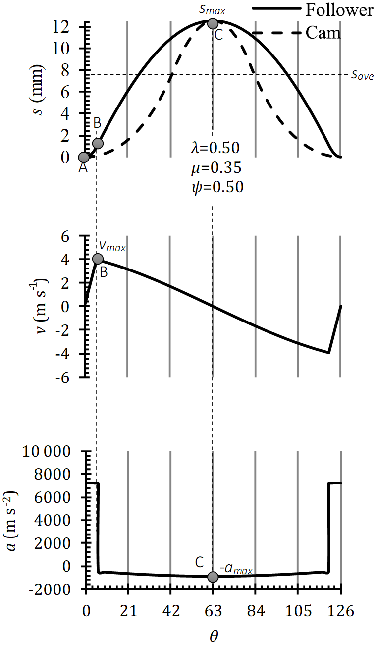
In Fig. 4, the cam follower characteristic (sθvθ and aθ) curves for which the vmax, amax, and save are shown were obtained for λ=0.50, ψ=0.50 and μ=0.35, respectively.
The design parameters for translating flat-faced follower mechanism with two-circular-arc cam are dimensionless to express independent of the basic parameters r, smax and θmax by means of the above equations. In this study, λ and ψ were changed between 0.10–0.90 and μ was changed between 0.25–0.45 and the design parameters were obtained and the criteria for optimum design parameter decision were discussed.
φ and κ parameters for cam profile design and vmax, amax and save parameters for follower movement were investigated. For each parameter, the graphs were obtained depending on μ, ψ and λ.
3.1 Effect of λ, ψ and μ on φ, and κ
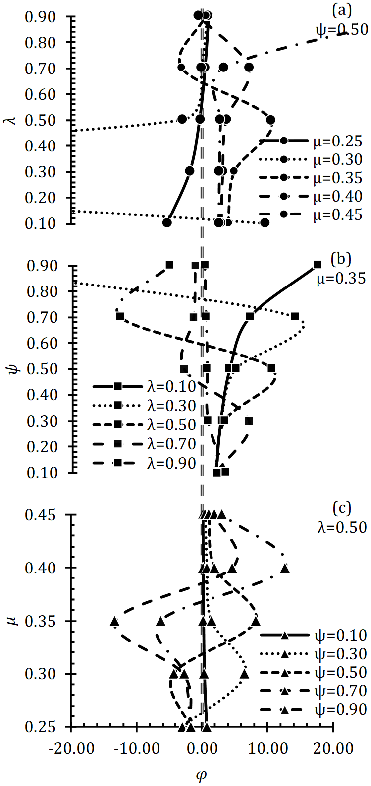
φ is one of the cam profile design parameters and must be greater than zero. Negative φ values indicate that the cam profile in these parameters is not possible. Because φ represents the distance between the base circle and the first arc centers and is a scalar parameter. The right side of the dashed line in Fig. 5 shows the possible cam profile. The left side of the dashed line refers to the cam profile which is not possible. However, φ should be of reasonable value. As φ increases, the curvature of the first arc profile (opening ramp) decreases and the curve is similar to the straight line. Therefore, φ≥1 is expected. When ψ is constant, the effect of λ on φ is examined (Fig. 5a), φ increases with increasing λ and begins to decrease after reaching maximum value. However, as the μ increases, the probability of φ being in the positive region (the right side of the dashed line) increases. When μ is constant (Fig. 5b), the effect of ψ on φ is examined, with the increase of ψ, φ increases and decreases after reaching maximum value. When the λ is constant (Fig. 5c), the effect of μ on φ can only be positive at the high values of μ. In order, for φ to be positive, λ and ψ should be low and μ should be high.
As the cam profile design parameter, κ is an expression of the first spring angle (θ1,max) in the cam profile. κ should always be positive. κ∕μ is the equivalent of θ1∕θ. and this value should always be positive. The right side of the dashed line in Fig. 6 refers to the possible cam profile. When the ψ is constant, the effect of λ on κ is examined (Fig. 6a), the κ∕μ decreases with the increase of λ. When μ is constant, the effect of ψ on κ∕μ is examined (Fig. 6b), κ∕μ decreases as ψ increases. When λ is constant (Fig. 6c), the effect of μ on κ∕μ is examined and κ∕μ increases as μ increases. In order for κ∕μ to be positive, λ and ψ should be low and μ should be high.

Figures 5 and 6 show that both φ and κ∕μ are positive for a possible cam profile. For example, in the case where λ and μ are 0.50 and 0.25 respectively, both φ and κ∕μ are not positive at all. Similarly, in the case where λ and μ are 0.90 and 0.35 respectively, φ can only be positive when ψ is too low. For this reason, it is not possible to obtain a cam profile in case any of the φ or κ∕μ is negative. It is also easier to obtain the possible cam profile as μ increases and ψ and λ decrease.
3.2 Effect of λ, ψ and μ on vmax, amax and savg
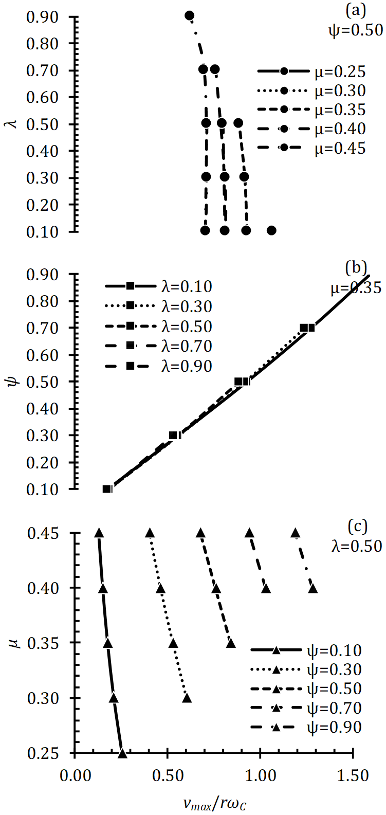
vmax, amax and save were examined for the effects of possible cam profiles on follower movements in cases where κ∕μ and φ were positive. At the junction point of two arcs (B-point in Fig. 4), the maximum velocity (vmax) occurs. The variation of vmax with respect to λ, ψ and μ is as shown in Fig. 7. When the ψ is constant (Fig. 7a), the vmax decreases slightly with the increase of λ. vmax increases with the increase of ψ when μ is constant (Fig. 7b). When λ is constant (Fig. 7c), vmax decreases slightly as μ increases. According to Fig. 7, for the vmax to be reduced, it is necessary to increase and/or decrease ψ. λ does not have a great effect on vmax.
The absolute acceleration is maximum (amax) at the peak (C-point in Fig. 4) where the follower movement direction changes. Therefore, it is desirable to low amax value. The variation of amax to λ, ψ and μ is as shown in Fig. 8. When the ψ is constant (Fig. 8a), the amax increases with the increase of λ. When the μ is constant (Fig. 8b), the amax decreases with the increase of ψ. When λ is constant (Fig. 8c), amax does not change according to μ. According to Fig. 8, it is necessary to increase ψ and/or decrease λ in order to decrease amax. μ has no effect on amax.

With the effect of a cam profile, the movement of the follower also changes, and the savg expresses the efficiency of that profile. In particular, it is expected that savg will be maximum in internal combustion engines. The variation of savg to λ, ψ and μ is as shown in Fig. 9. When the ψ is constant (Fig. 9a), savg increases with the increase of λ. When μ is constant (Fig. 9b), savg increases with increasing ψ. When λ is constant (Fig. 9c), savg decreases as μ increases. In order to increase the savg according to Fig. 9, it is necessary to increase the μ and/or λ and/or reduce the μ.
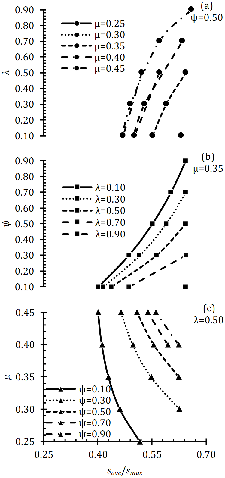
Table 1 shows the variation of vmax, amax and savg, which are evaluated for the tracer movement, with respect to λ, ψ and μ.
Table 1The effects of λ, ψ and μ on vmax, amax and savg.
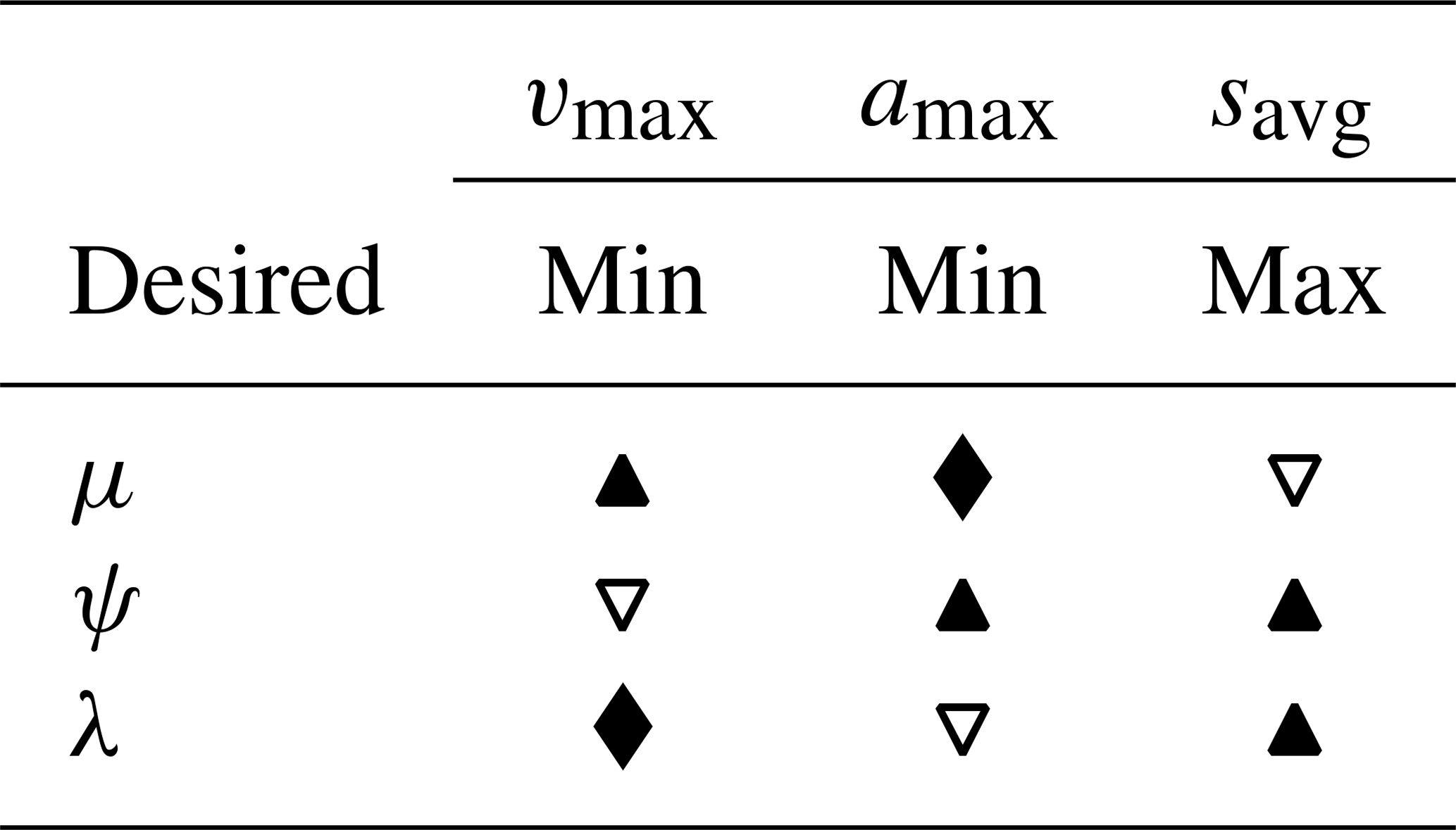
▴: increase, ▿: decrease, ⧫: no effect.
In Table 1, the selection of λ and μ for a cam profile is important. λ and μ refer to the radius of the second arc and the angular run time of the follower, respectively. In the design of the cam, μ is a decisive variable. Although it has an impact on the profile of the cam profile, it is usually a constant value and μ restricts the selection of other variables. In the case of λ, amax and save increases or decreases at the same time. However, it is desirable that amax is low and save is high. For this reason, it is important to select λ as an optimum. amax, which is a parameter related to the maximum operating speed (ωC), directly affects save. ψ is a parameter that depends on the follower lift and the parameter that determines this value is smax. However, smax also affects save Therefore, smax can be optimized by changing ψ for a situation where save is not changed or improved. With the increase in ψ, both amax and save improve. However, the base circle radius (r) with increasing ψ and smax is increasing accordingly. This is the growth of cam dimensions.
In this study, the design parameters for the translating flat-faced follower with two circular arc cam have been independent of dimension and the equations related to cam profile design and follower movements are obtained. λ, ψ, and μ were independent variables, φ and κ were used as dependent variables. The criteria for selecting vmax, amax and save, which are critical parameters for the follower, are presented as dimensionless and their effects are examined. As a result of the study, the effects of parameters affecting the cam profile and follower characteristics were investigated independently from the dimension. Accordingly, the effects of cam profile design parameters on cam performance criteria were determined. The fact that the mathematical model created was independent of the dimensions allowed the characteristic comparison of cam profiles of different structures. The results will be a reference for those interested in the design of the cam mechanism.
Data can be made available upon reasonable request. Please contact Emre Arabaci (earabaci@mehmetakif.edu.tr).
EA is responsible for all technical steps from conceptual design, equation formulation, numerical study and discussion.
The author declares that there is no conflict of interest.
This paper was edited by Xilung Ding and reviewed by two anonymous referees.
Arabaci, E., İçingür, Y., and Uyumaz, A.: Cam Design for Six-Stroke Engine with Water Injection Exhaust Heat Recovery, Gazi University Science Journal, Part C, 2, 213–220, 2014.
Bižić, M., Bulatović, R., Petrović, D., Gašić, M., and Savković, M.: Modeling profile and kinematic analysis of two circular-arc cams, Eng. Comput., 29, 535–546, https://doi.org/10.1007/s00366-012-0280-z, 2013.
Ceccarelli, M., Tavolieri, C., and Lanni, C.: An Experimental Analysis for Four Circular-Arc Cams. LARM: Laboratory of Robotics and Mechatronics-DiMSAT-University of Cassino Via Di Biasio, 43-03043, 2005.
Chen, F. Y.: A survey of the state of the art of cam system dynamics, Mech. Mach. Theory, 12, 201–224, https://doi.org/10.1016/0094-114X(77)90020-9, 1977.
Çınar, C. and Uyumaz, A.: Cam design and manufacturing for a homogeneous charge compression ignition gasoline Engine, J. Fac. Eng. Archit. Gaz., 29, 15–22, https://doi.org/10.17341/gummfd.42043, 2014.
Grohe, H. and Russ, G.: Otto-und Dieselmotoren, Vogel Buchverlag, 78–86, 2010.
Hsieh, J. F.: Design and analysis of cams with three circular-arc profiles, Mech. Mach. Theory, 45, 955–965, https://doi.org/10.1016/j.mechmachtheory.2010.02.001, 2010.
Kim, S. H. and Ahn, Y. J.: An approximation of circular arcs by quartic Bézier curves, Comput. Aided Design, 39, 490–493, https://doi.org/10.1016/j.cad.2007.01.004, 2007.
Lanni, C., Ceccarelli, M., and Carvalho, J. C. M.: An analytical design for two circular-arc cams. In Proceedings of the Fourth Iberoamerican Congress on Mechanical Engineering, Santiago de Chile, 100–105, 1999.
Lanni, C., Ceccarelli, M., and Figliolini, G.: An analytical design for three circular-arc cams, Mech. Mach. Theory, 37, 915–924, https://doi.org/10.1016/S0094-114X(02)00032-0, 2002.
Lin, S., Jusko, O., Härtig, F., and Seewig, J.: A least squares algorithm for fitting data points to a circular arc cam, J. Measurement, 102, 170–178, https://doi.org/10.1016/j.measurement.2017.01.059, 2017.
Xiaoyi, J.: Kinematics on Six Circular Arc Disk Cam Mechanism with Translating Follower, Journal of Southeast University (Natural Science Edition), 4, 82–87, 1999.