the Creative Commons Attribution 4.0 License.
the Creative Commons Attribution 4.0 License.
 | 11 Jan 2019
Compact design of a novel precise cable drive mechanism with high precision and large torque-to-weight ratio
Xin Xie
Xianliang Jiang
Shixun Fan
Dapeng Fan
Precise cable drive is an elegant transmission mode and has many advantages of high efficiency, flexible layout, besides being lightweight. Since the common layout, Single-Input Single-Output (SISO) spur gear configuration, suffers from low torque-to-weight ratio and loose structure, this paper proposes a novel transmission configuration with large torque-to-weight and compact size. It combines the advantages of Multiple-Input Single-Output (MISO) configuration and bevel gear configuration. The design methods and transmission kinematics of the novel configuration are studied. An analytical model is developed for characterizing the transmission backlash of the proposed configuration, which is derived by simultaneous satisfying system's constitutive relation, equilibrium, and geometric constraints. Parametric sensitivities are carried out to investigate the influence of the major design parameter on the transmission characteristics. At last, a prototype of MISO with bevel gear configuration cable drive mechanism (MBCDM) is built, with which a series of experiments are carried out. This mechanism could achieve maximum output torque of 3.3 Nm with considerable toque-to-weight ratio of 9.649 Nm kg−1. The experimental results show that the transmission backlash and ripple torque are dominant nonlinear effects in the MBCDM system. It shows that the ripple torque is connected with the rotational displacement, with the highest peak at 694.3 cycle rad−1 and the amplitude of 24.67 µrad. The transmission backlash experimental results are in good agreement with simulation ones, with the error level of 4.14 %.


Precise cable drive (Lu et al., 2011; Lu, 2013; Lu and Fan, 2013; Fan et al., 2018) is an elegant transmission mode and has many advantages of high efficiency, flexible layout, besides being lightweight. These properties make precise cable drive widely used in the acquiring tracking and pointing (ATP) applications (Ren and Stephens, 2015), such as free space laser communication system (Sofka, 2007; Korevaar and Bloom, 1993), satellite remote sensing platform (Li et al., 2015; Zhang et al., 2013) and hybrid active vision robot (Dankers and Zelinsky, 2004; Sutherland et al., 2000). But in some special applications such as stabilized sighting system or infrared imaging seeker (Lu et al., 2015; Debruin and Royalty, 1996), it is expected that the precise cable drive mechanism not only features high position control accuracy, but also possesses a large torque-to-weight ratio. Furthermore, it is necessary to be compact for the highly confined spaces in such applications. Therefore, this paper is concentrated on the design and performance analysis of a one degrees-of-freedom(DOF) novel configuration precise cable drive mechanism which has high pointing precision, light weight, large torque-to-weight ratio and compact structure.
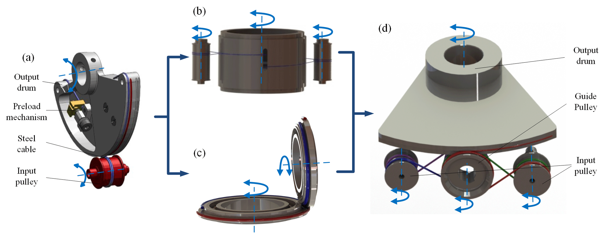
Figure 1Development of the proposed transmission configuration: (a) the SISO spur gear configuration (cited in Lu and Fan, 2013); (b) the MISO configuration; (c) Bevel gear configuration; (d) a combination of MISO and bevel gear transmission configuration.
Single-Input Single-Output (SISO) spur gear configuration (Lu et al., 2011; Sofka, 2007) is the most common layout of the precise cable drive mechanism, due to its merits including elegant simplicity, low inertia and high efficiency. But this configuration suffers from low torque-to-weight ratio and loose structure. The restrictive condition is the minimum bend radius of the cables that prevents the use of smaller diameter pulleys (Truong et al., 2000). In response, a Multiple-Input Single-Output (MISO) configuration (Carson, 1988) whose multiple input pulleys connected by cables to a single output drum has been developed to obtain high output torques. But it is still difficult in decreasing the volume, as the single output drum axis should be parallel to that of the input pulleys. Moreover, the SISO bevel gear configuration (Truong et al., 2000; Dankers and Zelinsky, 2004; Salisbury and Townsend, 1993) that transmits torque across orthogonal shafts is adopted to save space in many precise cable drive mechanisms. But the transmission ratio is also restricted within the available work space. Inspired by the aforementioned research, a novel transmission configuration is initially proposed in this article. It combines the advantages of MISO configuration and bevel gear configuration. It can substantially increase the torque-to-weight ratio within a compact size.
Past studies have involved the design and performance analysis methods of the precise cable drive (Baser and Konukseven, 2010; Kilic and Dolen, 2014; Lu and Fan, 2013; Jung et al., 2008), but most of those have focused on SISO configuration. The following issues need to be considered for the proposed novel configuration. (a) In order to reduce the structural dimensions and total mass under the desired output torque, it is necessary to optimize the number of driving shafts, transmission ratio, and cable diameter. (b) As a theoretical research focus, to find out what will deteriorate position accuracy in the new configuration has great practical significance. (c) It is necessary to develop an analytical model for characterizing the transmission backlash of the proposed configuration cable drive mechanism.
The main purpose of this study is to provide a base model of a combination of MISO and bevel gear transmission configuration precise cable drive mechanism for addressing the above problems. Specifically, the novel configuration is introduced and the design methods are studied, including transmission configuration and transmission kinematics. An analytical model of transmission backlash is derived by simultaneous satisfying the system's geometric, constitutive relation and equilibrium constraints. Next, parametric sensitivities are carried out to investigate the influence of the major design parameter on the transmission characteristics. At last, a prototype of MISO with bevel gear configuration cable drive mechanism (MBCDM) has been built, with which a series of experiments are carried out. The driving capability is validated through experiments. The dominant nonlinear factors for deteriorating the position control accuracy are analyzed based on experimental results in such a system. The transmission backlash is tested, and corresponding results are in good agreement with theoretical ones.
2.1 Transmission configuration design
The SISO spur gear configuration is a typical layout, as shown in Fig. 1a. The input pulley and output drum are connected by steel cable in a figure eight pattern, with a preload mechanism at one end. A proper preload force is exerted on the cable to prevent slack and improve transmission capability. The steel cable is usually wound around the input drum for several circles to increase the wrap angle. But the transmission capacity is limited by the SISO configuration on the condition that either the single electric motor size or torque is restricted. In response, the MISO configuration of precise cable drive has been put forward to enlarge transmission capacity under a restricted weight, as shown in Fig. 1b. It includes multiple input pulleys connected by separate cables to a single output drum. The input pulleys are evenly placed around the output drum. Each steel cable wraps around one of the input pulleys and the same output drum to transmit the motion to the output shaft. Each cable would be pre-tensioned by the preload mechanism at one end. Moreover, the bevel gear is used for transmitting motion across orthogonal shafts, as shown in Fig. 1c. In this configuration, two cables cross over from input pulley to output drum at a transfer point to provide bi-directional rotation. In order to prevent the cables cross over at an exact same point, the pulleys are axially stepped and two cables wrap on each step. Each cable is terminated and pre-tensioned at ends. It could decrease the size along the axes of the output drum.
In order to extremely improve the torque-to-weight ratio with a compact structure, this paper initially proposes a novel transmission configuration which utilizes a combination of MISO configuration and bevel gear configuration, as shown in Fig. 1d. It is composed of four pulleys, four cables and preload mechanisms. The input pulleys and the guide pulley are parallel to each other, and they are all perpendicular to the output drum. Each input pulley is wrapped by two cables to provide bi-directional rotation. It is noted that the pulleys are axially stepped to produce two smooth surfaces on input pulleys and four smooth surfaces on guide pulley and output drum, without flanges or grooves to guide the cable. Because grooves or flanges on the surface will cause the scrubbing when the cable jump from guide pulley to output drum at the transfer point. The guide pulley and the output drum should be placed closely at the transfer point to facilitate the transition of the cable between the pulleys.
Several advantages exist for the novel configuration proposed in this paper. First of all, this layout can employ dual motors to drive an output pulley. Under the premise of achieving the same driving ability, this novel configuration can obtain larger torque-to-weight ratio than the basic SISO spur gear configuration. It is crucial for the applications with highly confined spaces. Secondly, it is an effective way of saving space by utilizing the bevel gear configuration. Thirdly, an advantage of the multi-motor drive is redundancy for applications requiring high rotary stiffness. The rotary stiffness would increase as the number of steel cable increase, and as the number of input shafts increase. At last, this configuration has better security and lower probability of failure. If multiple drive shafts are employed, and one should fail, the other shafts will work as usual. The main drawback of this configuration can be considered as a fundamental limited roll rotation, which bars their general use in power trains, but it is enough for the fields of stabilized sighting system or infrared imaging seeker.
2.2 Transmission kinematics

Figure 2Kinematic sketch of the novel transmission configuration with globe and local axes: (a) vertical view; (b) side view.
It is clearly seen in Fig. 2, the motion of the output pulley (θo) is transmitted from the two motors (θml, θmr). The guide pulley (θg) is used to change the direction of motion. The four colored curves represent the cables utilized in this transmission configuration. The cables are all terminated in the input pulleys at one end and pretensioned in the output drum at the other. It is defined as θo=0 when the Z axis of output pulley is parallel with the Z axis of the others. It is also defined as θg=0, θml=0, θmr=0 when the Y axis of guide pulley, or left input pulley, or right input pulley is parallel with the Y axis of output drum, respectively. The output drum is perpendicular to the others. The output drum rotates around the Y axis, and the others rotate around the Z axis. The anticlockwise direction around the rotational axes is defined as the positive angle.
The cylinders are all axially stepped and separate cables run on each step to provide bi-directional rotation. The two input pulleys are designed as a form of two stairs, the radius as (rml1>rml2) and (rmr1>rmr2), respectively. The guide and output pulleys are designed as a form of four stairs, the radius as () and (), respectively. According to the geometric constraints, the following expressions for the radius of the pulleys should be satisfied.
where ig, iml, imr represent the transmission ratio between output and guide pulley, left input and guide pulley, right input and guide pulley, respectively.
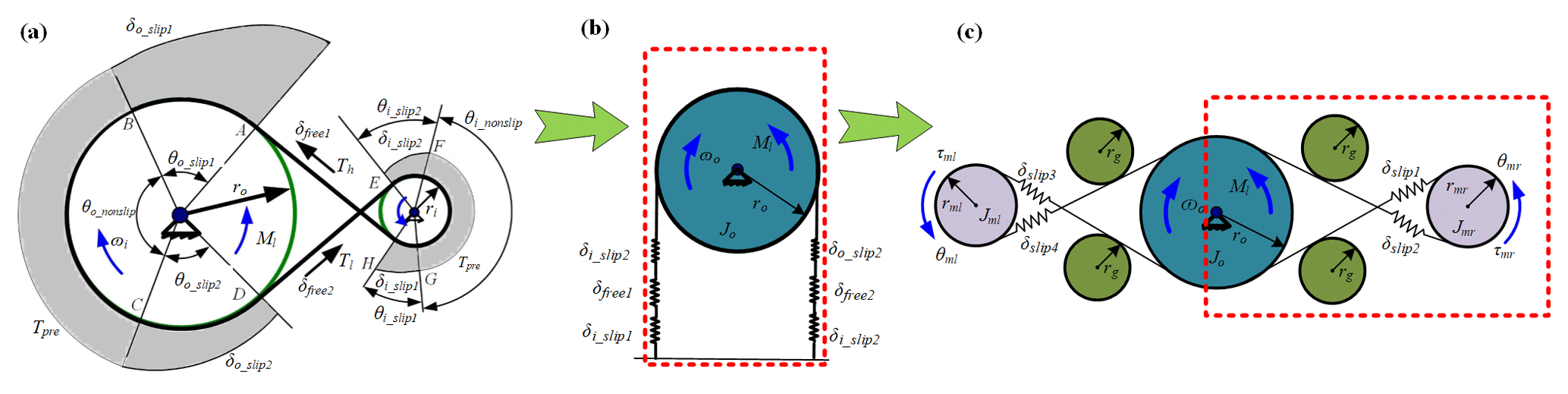
Figure 3Development of transmission backlash model of proposed configuration: (a) tension profile and Affected angles of wrap; (b) equivalent model of SISO configuration; (c) equivalent model of proposed configuration.
Transmission backlash exists due to the elasticity of the cables and the load acting on it. This behavior not only deteriorates the control accuracy, reducing the bandwidth, causing limit cycle oscillation and leading to steady-state vibration, but also is a major factor giving rise to nonlinear dynamic response, such as frequency jump, chaos and bifurcation. Therefore, it is significant to model the backlash characteristics of the proposed configuration.
To better understand the generating mechanism of the transmission backlash, we define transmission error as the deviation between the actual position output, θo, and the desired position output (position input, θi, divided by transmission ratio, ic), namely,
Transmission backlash is defined as the amount of the abrupt variation of the transmission error. It is originated from the change in elastic elongation of the cable, which in turn results from the abrupt change in applied load. Determining the cable tension requires the knowledge of the equilibrium tension profile in the contact region, which could be derived by the classical creep theory. This theory assumes that friction is developed due to the relative slip motion between the cable and the pulley, and a Coulomb law describes the cable-pulley friction (Kong and Parker, 2005).
Figure 3a shows the tension and affected angles of wrap in SISO configuration when an external load Ml is applied to the output drum. As a result, the cable tension of the free length AH and DE change to Th and Tl from a uniform preload force, Tpre, respectively. The affected slip angles can be divided into three parts on input pulley (radius, ri) θi_slip1, θi_nonslip, θi_slip2, and three parts on output drum (radius, ro) θo_slip1, θo_nonslip, θo_slip2, respectively. Assuming that the output drum rotates in the counterclockwise direction initially. Thus AH and DE become the tight side and the slack side, respectively. The equivalent spring model of SISO configuration is shown in Fig. 3b. The deformations of cable could be divided into two parts due to the variation of the cable tension of free length. The deformation of cable on side1 (δo_slip1, δfree1, δi_slip1) is elongated due to the cable tension of the free length AH increases. And the deformation of cable on side2 (δo_slip2, δfree2, δi_slip2) is shortened due to the cable tension of the free length DE decreases. As to the proposed configuration, the equivalent model is depicted in Fig. 3c. The two input pulleys bear the external load simultaneously. When the external load applies to the output drum, the deformations of cable on side1 and side4 are both shorten and the deformations of cable on side2 and side3 are both elongated. Based on the torque equilibrium equation, the cable tension of the free length can be obtained as
The tension in the slip region T(θ) and slip angles could be derived as,
According to the Hooke's law (Baser and Konukseven, 2010), the cable deflection in the corresponding slip region and free cable segment, namely δo_slip1, δo_slip2, δi_slip1, δi_slip2, δfree could be written as,
Assuming that the overall length of the cable remains unchanged, the geometric constraint is therefore
Substituting the torque equilibrium equation (Eq. 3), the cable deformation in the corresponding slip region Eqs. (7)–(12) into the geometric constraint (Eq. 13) to get the cable tension on the free length.
The pulleys usually are close together to increase wrap angle and decrease the axial force of the pulleys in the proposed prototype. The free length distance would be very small in this configuration. And the friction coefficient, μ, generally ranges from 0.15 to 0.2. We could assume that
Then, the Eq. (14) could be simplified as
Solving for Tl and Th we find
The transmission backlash, θb, is equal to the cable deflection on one side, δslip_BAHG or δslip_CDEF, divided by the output drum radius, ro.
Substituting the Eqs. (7), (9) and (11) into Eq. (19), we can obtain the backlash angle of this novel configuration precise cable drive.
In order to validate the design and performance analysis methods of the proposed configuration, the parametric sensitivities would be investigated after determining the specific parameters.
4.1 Parameter determination
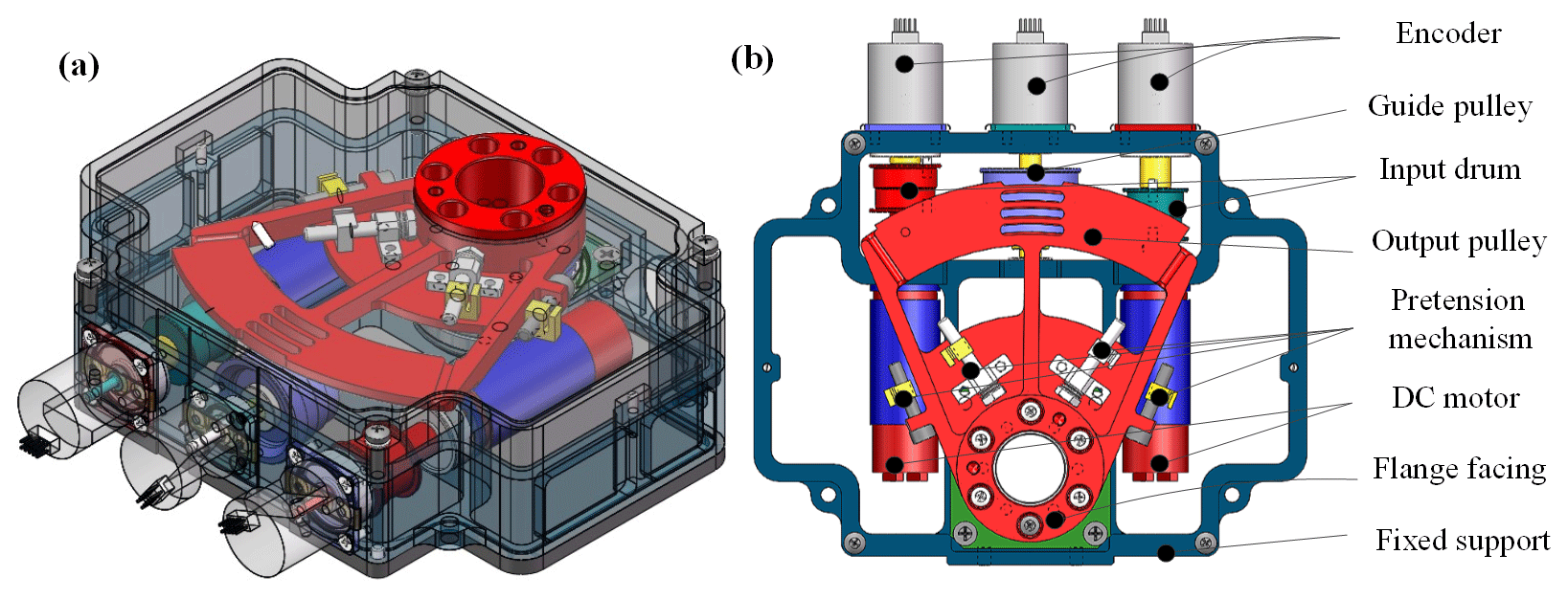

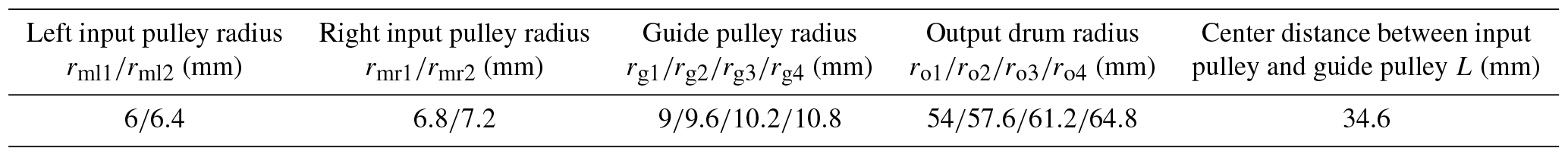
Shape and configuration of the designed 1-DOF MISO with bevel gear configuration cable drive mechanism (MBCDM) are shown in Fig. 4. The mechanism includes fixed support, DC motors, input pulleys, guide pulley, output drum, pretension mechanism and encoders. Two DC motors are mounted on the fixed support in parallel to rotate the two input pulleys. Then the force and motion transmit to output drum across orthogonal shafts which can save space effectively. Turnbuckles at the point where the cables terminate on the pulley surface are used as the pretension mechanism. Three optical encoders are attached on the shafts to sense its rotary motion. Each input pulley is drived by a DC motor (2.9 mN × m, 18g) and gearboxes (76 : 1). The material properties of the selected cable and the geometry parameters of the developed MBCDM are shown in Tables 1 and 2, respectively. In this way, MBCDM can obtain a large torque-to-weight Ratio (11.14 Nm kg−1) with a light weight (350g) theoretically. The volume of the mechanism is mm3.
4.2 Parameter sensitivities
Based on the proposed transmission characteristics models, parametric sensitivities are carried out to investigate how the design parameters affect the proposed transmission characteristics. It is noted that when one of parameters varies, the others remain the initial value. Using the parameters in Tables 1, 2 and μ=0.15 as the initial values in the simulation.
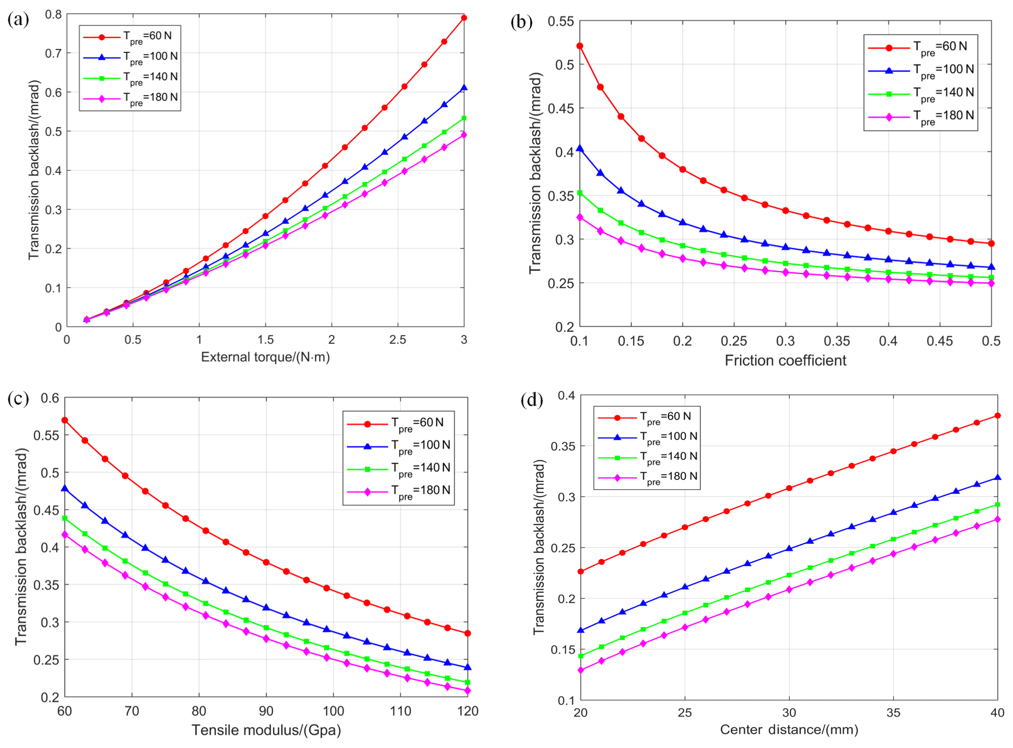
Figure 5Parametric sensitivity analysis for transmission backlash: (a) the effect of preload and external torque; (b) the effect of preload and friction coefficient; (c) the effect of preload and tensile modulus; (d) the effect of preload and centre distance.
From Eq. (20), transmission backlash mainly determined by five cases, which are preload force Tpre, external torque Ml, friction coefficient μ, tensile modulus E, and center distance L. The initial values of the parameters of the mechanism are shown in Tables 1 and 2. The parametric analysis results of the proposed configuration are presented in Fig. 5.
As shown in the figure, the transmission backlash decreases as the increase of preload force, friction coefficient and tensile modulus, or as the decrease of external torque and center distance. Therefore, the optimized design should maximize one performance indicator on the premise of ensuring the sufficiency of the others. The external torque is the most sensitive parameter among the design parameters. Thus, external torque should be first considered in the parameter adjustment phase. The backlash plunges dramatically when the friction coefficient is small, and flattens out since friction coefficient larger than 0.3. It is also important to increase the friction coefficient to a threshold value by lubrication or other methods.
Moreover, the tensile modulus of the cable increases as the cable diameter increases, as shown in Fig. 5c. On the other hand, it is known that the bending stress of cable would be increased when a radius ratio of the cable radius to the pulley radius is getting decreased. This leads to an increase in wear between strands, which greatly reduces cable fatigue life. Therefore, a trade-off should be made between the transmission backlash and fatigue life when selecting the cable.
Preload force is the main parameter to regulate the behavior of the transmission characteristics. By increasing the preload force, the system could achieve lower transmission backlash, but the rate of decrease is reduced. It is necessary to find the threshold value of preload force to keep the backlash in a stable state. The results of the parameter sensitivities provide some suggestions about optimizing the transmission characteristics.
In order to validate the proposed design and performance analysis methods, a prototype of the designed MBCDM has been constructed, as shown in Fig. 6a. All components are assembled together carefully and the MBCDM possesses a compact structure and light weight with 342g. The experimental system mainly consists of the MBCDM, torque sensor (Kistler 9349A, with measuring range of ±30 Nm), optical encoder A (AEDA-3300TBN, with resolution of 191.74 µrad), optical encoder B (HEIDENHAIN RON285, with resolution of 1.364 µrad), inertial plate, torque motor, magnetic powder brake, and dSPACE1103 semi-physical simulation system. The optical encoder A and the optical encoder B are used to obtain the rotational displacement of input and output shaft, respectively. The torque sensor is utilized to measure the real-time torque on the shaft. The inertial plate is mounted on the test apparatus to simulate the mass unbalances. The torque motor is installed at one end to test the driving capability of the MBCDM, as shown in Fig. 6b. The transmission backlash would be tested when the torque motor is replaced by the magnetic powder brake, as shown in Fig. 6c. A dSPACE system (DS-1103) is utilized to decode the feedback signals and generate real-time codes for such a system.
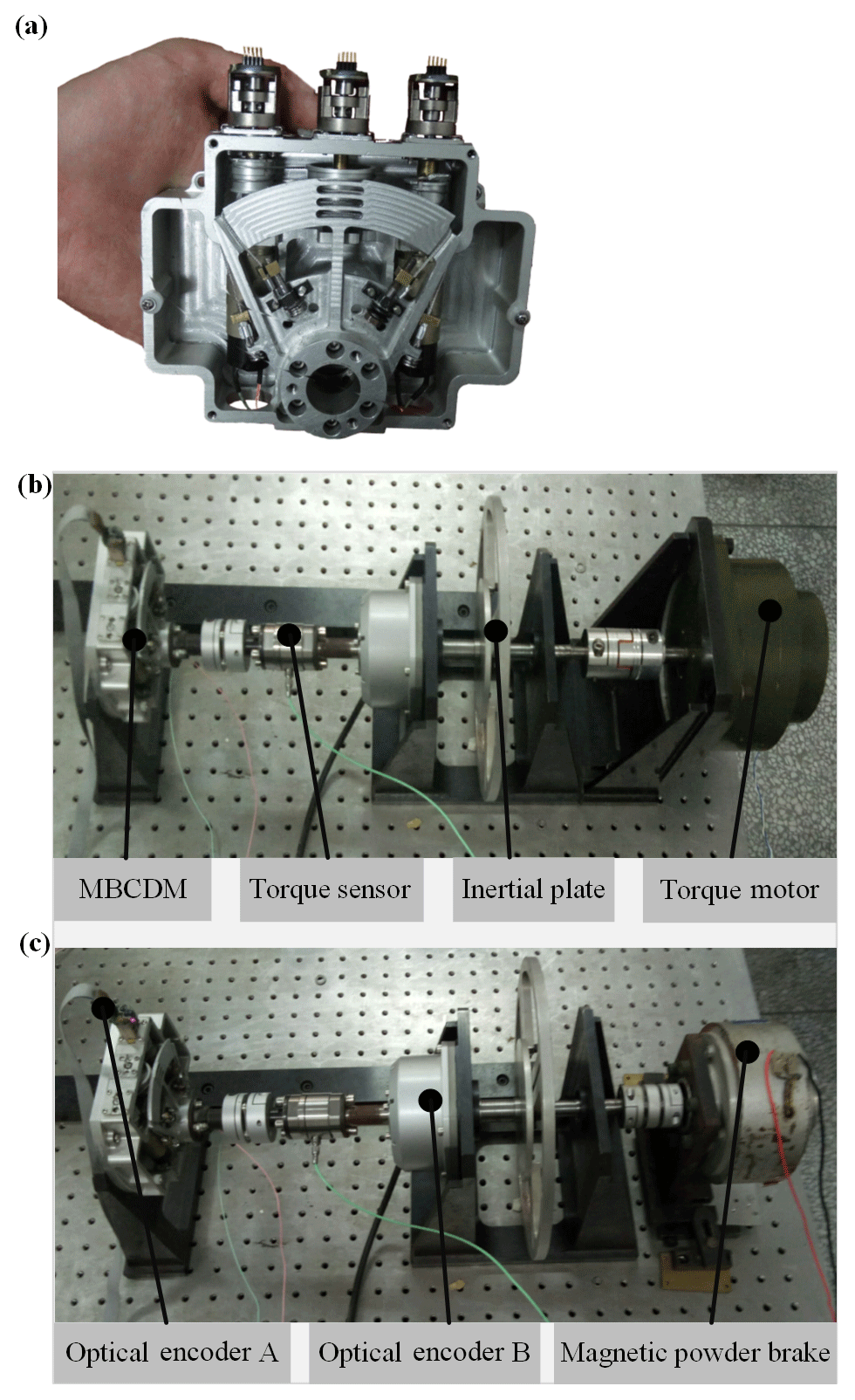
Figure 6Experimental setups of MBCDM: (a) prototype of the MBCDM; (b) driving capability test; (c) transmission backlash test.
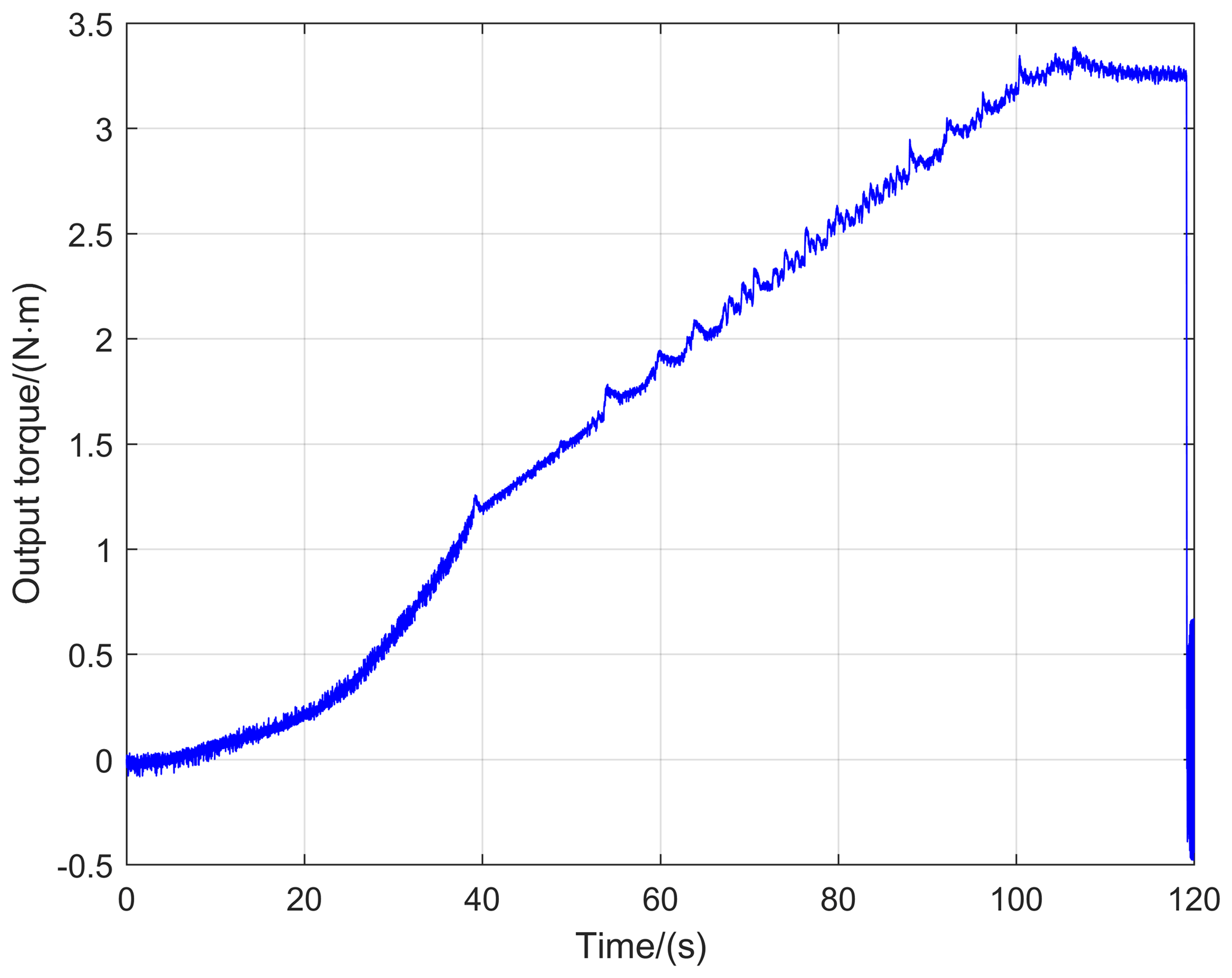
5.1 Driving capability test
To test the driving capability of the MBCDM, the torque motor is installed at one end, as shown in Fig. 6b. The MBCDM system works in the position closed-loop mode. Meanwhile, the torque motor gives a low slope ramp signal on the condition of open loop. Figure 7 shows the time history of real-time output torque measured by the torque sensor. The maximum output torque is about 3.3 N × m, which is slightly less than the theoretical value of 3.9 N × m. The reasons include the preload is hard to reach the designed value and the synchronous control problems of the dual motors. It would be an effective method to improve the driving capability by increasing the wrap angle or transmission ratio. But it deserves to note that this system has reached a considerable toque-to-weight ratio of 9.649 N × m kg−1 with a compact size. The advantages of the MISO with bevel gear configuration have been fully shown in this experiment.
5.2 Positioning performance test
Figure 8a shows the experimental results for a 0.05 Hz sinusoidal excitation with the amplitude of 100 mrad. The left ordinate depicts the time history of the reference and angular response and the right ordinate presents the angular response error. The angular response error is defined as the difference of the reference and actual rotational displacement of output shaft. It can be observed that the amplitude of the tracking error is about ±0.3 mrad. The transmission backlash and ripple torque are dominant nonlinear effects in the MBCDM system. The former one is usually appeared at the moment when the direction of motion is changed. The performances of the precise cable drive mechanism are mainly restricted by its transmission backlash, which could reach several hundred microradians. The generating mechanism, along with comparison results of transmission backlash are presented later. The latter one is a deviation from desired torque, which could lead to speed oscillations, deteriorating the position control accuracy. The reasons for ripple torque of precise cable drive are plentiful, such as repetitive contact, load variation and DC current offset from the motor. Figure 8b shows the spatial frequency spectrum of the angular response error. The highest peak is measured at 694.3 cycle rad−1 with the amplitude of 24.67 µrad. It shows that the ripple torque in MBCDM is a function of the rotational displacement. The effect could be modeled and suppressed to improve the position control accuracy.
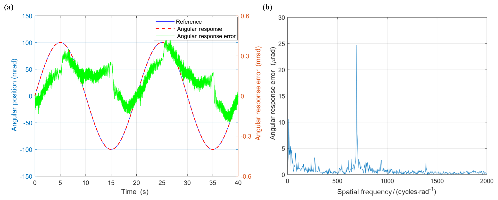
Figure 8Positioning performance test results: (a) reference, angular response and position error to a sinusoidal excitation with the amplitude of 0.1 mrad and frequency of 0.05 Hz; (b) spatial frequency spectrum of transmission error.
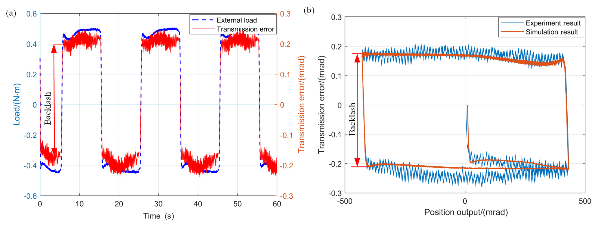
Figure 9Test results for transmission backlash: (a) the time history of external load and transmission error; (b) comparison of experimental and simulation results of transmission backlash.
5.3 Transmission backlash test
The magnetic powder brake is installed to test the transmission backlash of the MBCDM, as shown in Fig. 6c. In order to keep the pulleys in quasi-static condition to avoid the cable vibration due to resonance, the MBCDM is excited by a sinusoidal signal of frequency of 0.1 Hz and amplitude of 50 mrad in position closed-loop control mode. Transmission error could be calculated by Eq. (2), with the real-time rotational displacement of input and output shaft from optical encoder A and B. Figure 9a shows that the external torque and transmission error undergo a sudden change simultaneously. Transmission backlash is defined as the amount of the abrupt variation. The experimental results prove that transmission backlash is originated from the abrupt change of the external load. Figure 9b shows that each of the experimental and simulation results of transmission backlash varies with position output. The simulation results are calculated by the experimentally measured external load and other parameters given above. The simulations capture all the major trends observed in experiments and match the numbers closely. In the experimental results, we observe that the transmission backlash emerges at the time when we apply external load initially to the preloaded cable and the time when we reverse the direction of the motion, as predicted by simulations. Using RMSE (Root Mean Square Error) to evaluate the goodness of fit between the simulation and experimental results. The RMSE for the proposed model in this case is about 4.14 %. The actual transmission backlash is about 0.33 mrad when Tpre=70 N, Ml=0.91 Nm. The difference between the theoretical value derived by Eq. (20) and the experimental result is approximately 9.7 %. It can be concluded that the results of theoretical analysis are in good agreement with experimental ones. The research results in this paper would be useful in the mechanical design, as well as for the purpose of devising precision motion control laws for this novel configuration precise cable drive mechanism.
However, only the driving capability, positioning performance and transmission backlash test are conducted, and further experiments on the transmission stiffness, and parametric sensitivities could be proceeded to completely characterize the behaviour of the MISO with bevel gear configuration precise cable drive mechanism.
This paper investigates the design and performance analysis of a MBCDM with high precision and large torque-to-weight ratio. The mechanical design methods, including transmission configuration and transmission kinematics are elaborated. Analytical methods are successfully developed to model the transmission backlash of the proposed configuration. Affect and sensitivity of major design parameters on the transmission characteristics are analyzed. A prototype of the MBCDM is fabricated, with which a series of experiments are carried out. The results testify that the MBCDM could provide good performance. From the research results, the following conclusions have been drawn:
- a.
This configuration combines the advantages of MISO configuration and bevel gear configuration. The fabricated mechanism could achieve a maximum output torque of 3.3 Nm with considerable toque-to-weight ratio of 9.649 N × m kg−1.
- b.
The experimental results show that the transmission backlash and ripple torque are dominant nonlinear effects in the MBCDM system. It shows that the ripple torque is a function of the rotational displacement in such a system, with the highest peak at 694.3 cycle rad−1 and the amplitude of 24.67 µrad.
- c.
The generating mechanism of the transmission backlash is clarified. It emerges at the moment when the applied load undergoes a sudden change. The transmission backlash experimental results are in good agreement with simulation ones, with the error level of 4.14 %.
The research results in this paper would be useful in the mechanical design, as well as for the purpose of devising precision motion control laws for this novel configuration precise cable drive mechanism.
The data generated during this study are available from the corresponding author on reasonable request.
The authors declare that they have no conflict of interest.
This research is supported by the National Key Basic Research Program of
China (973 Program, No.2015CB057503), National Natural Science Foundation of
China (No. 51475467). The authors would also like to thank the reviewers for
their excellent comments and suggestions.
Edited by: Chin-Hsing Kuo
Reviewed by: two anonymous
referees
Baser, O. and Konukseven, E. I.: Theoretical and experimental determination of capstan drive slip error, Mech. Mach. Theory, 45, 815–827, 2010.
Carson, D. G.: Rotary drive apparatus having multiple drive shafts, United States Patent 4787259, 1988.
Dankers, A. and Zelinsky, A.: CeDAR: A real-world vision system: Mechanism, control and visual processing, Mach. Vision Appl., 16, 47–58, 2004.
Debruin, J. C. and Royalty, J. M. B.: Feedforward stabilization test bed, Proc. Soc. Photo-Opt. Ins., 2739, 204–214, 1996.
Fan, D. P., Xie, X., Qi, C., Fan, S. X., and Zhang, L. C.: Research on status and analysis of precise cable drive technology, Optics and Precision Engineering, 26, 1078–1097, 2018.
Jung, J. H., Pan, N., and Kang, T. J.: Capstan equation including bending rigidity and non-linear frictional behavior, Mech. Mach. Theory, 43, 661–675, 2008.
Kilic, E. and Dolen, M.: Prediction of slip in cable-drum systems using structured neural networks, P. I. Mech. Eng. C.-J. Mec., 228, 441–456, 2014.
Korevaar, E. J. and Bloom, S. H.: Status of SDIO/IS&T lasercom testbed program, P. Soc. Photo-Opt. Ins., 1866, 116–127, 1993.
Kong, L. and Parker, R. G.: Steady Mechanics of Belt-Pulley Systems, J. Appl. Mech., 72, 25–34, 2005.
Li, X. Y., Li, Q. J., Zhang, X. F., Yang, Y. M., and Zhang, J. G.: Disturbance suppression and compensation of flexible transmission system of aerial camera, Chin. J. Sci. Instrum., 36, 13–19, 2015.
Lu, Y.: Study on the Principle and Design Method of the Precise Cable Drive, PhD thesis, National University of Defense Technology, Changsha, 2013.
Lu, Y. and Fan, D.: Transmission backlash of precise cable drive system, P. I. Mech. Eng. C.-J. Mec., 227, 2256–2267, 2013.
Lu, Y., Liao, H., Mo, H., Liu, H., and Fan, D.: Development of a differential cable drive mechanism for acquiring tracking and pointing application, P. I. Mech. Eng. C.-J. Mec., 229, 3191–3200, 2015.
Lu, Y. F., Fan, D. P., Sheng, D. J., and Zhang, Z. Y.: Design Consideration for Precise Cable Drive, Adv. Mat. Res., 305, 37–41, 2011.
Ren, Z. and Stephens, L. S.: Laser Pointing and Tracking Using a Completely Electromagnetically Suspended Precision Actuator, J. Guid. Control Dyna., 29, 1235–1239, 2015.
Salisbury, K. J. and Townsend, W. T.: Compact cable transmission with cable differential, United States Patent 5046375A, 1993.
Sofka, J.: New generation of gimbals systems for aerospace applications, Dissertations & Theses – Gradworks, 2007.
Sutherland, O., Rougeaux, S., Abdallah, S. and Zelinsky, A.: Tracking with hybrid-drive active vision, International symposium on experimental robotics, Honolulu, December 2000, 1–6, 2000.
Truong, H., Abdallah, S., and Rougeaux, S.: A Novel Mechanism for Stereo Active Vision, Proceedings of Australian conference on robotics and automation (ACRA2000), Melbourne Australia, August 2000, 1–6, 2000.
Zhang, H. W., Cao, G. H., Li, Y. W., Zhang, L., and Ding, Y. L.: Application of wire rope gearing in aerial optical remote sensor, Laser & Infrared, 43, 418–422, 2013.