the Creative Commons Attribution 4.0 License.
the Creative Commons Attribution 4.0 License.
 | 12 Aug 2019
A holographic matrix representation of the metamorphic parallel mechanisms
Wei Sun
Jianyi Kong
Liangbo Sun
Metamorphic mechanisms belong to the class of mechanisms that are able to change their configurations sequentially to meet different requirements. In this paper, a holographic matrix representation for describing the topological structure of metamorphic mechanisms was proposed. The matrix includes the adjacency matrix, incidence matrix, links attribute and kinematic pairs attribute. Then, the expanded holographic matrix is introduced, which includes driving link, frame link and the identifier of the configurations. Furthermore, a matrix representation of an original metamorphic mechanism is proposed, which has the ability to evolve into various sub-configurations. And evolutionary relationships between mechanisms in sub-configurations and the original metamorphic mechanism are determined distinctly. Examples are provided to demonstrate the validation of the method.


Compared with the traditional mechanisms which usually have fixed mobility, metamorphic mechanisms are a multi-topological structure, in terms of economy, adaptability and efficiency, and prevails the traditional ones. Metamorphic mechanisms were proposed by Jiansheng Dai and John Rees Jones in 1996 based on the idea of reconfiguration (Dai and Rees John, 1999), which contributed to the new field of modern mechanical development and attracted the attention and interest of the theory of mechanism researchers around the world. In the past two decades, the research of principles and applications in metamorphic mechanisms has made a great breakthrough. The variation mode of metamorphic mechanism has been added to variable attribute of components, variable orientation of kinematic joints, friction self-locking joint units (Gan et al., 2009, 2010; Zhang et al., 2013; Ding and Li, 2015; Ye et al., 2016). Therefore, in order to create topological variations in the characteristics of mechanisms in different configurations, the appropriate structural representation for a metamorphic mechanism has been researched (Li et al., 2011a, 2016).
Mechanism diagram, topological graph and traditional adjacency matrix are simple and intuitive tools for describing a mechanical structure in a single sub-configuration. In order to analyze the configurations of the metamorphic mechanism, a basic transformation matrix which uses adjacency matrices to represent institutional changes was proposed by Dai et al. (2005). And a description method of displacement subgroup for structural transformation of the metamorphic mechanism was proposed (Zhang and Dai, 2009). Li et al. (2011b) found that the constraint graph of computational geometry rather than the traditional topological graph to characterize a metamorphic linkage. The joint-gene based variable topological representation is proposed, and the method and procedures for the configuration transformations were presented based on the topological representation (Li et al., 2009). The constraint function was defined according to the constraint features of kinematic joints. With constraint functions as elements, the adjacent matrix of the original kinematic chains of metamorphic mechanism was proposed (Liu, 2012). Li and Dai (2011) introduced an augmented adjacency matrix with the connectivity of links, the types of joint and its axis-orientation. Due to the lack of discussion on the variation of the metamorphic mechanism, the matrix operations of these methods are still EU operations. The EU-elementary matrix operation consists of the steps of applying an Ui,j-elementary matrix operation and an elimination Ej-elementary matrix operation used in pairs (Dai and Rees John, 2005).
In order to describe the changes between different configurations in the process further and better, Zhang et al. (2016) introduced a comprehensive symbolic matrix representation for describing the topological structure. An element “−1” was introduced to indicate the frozen kinematic pairs, which given an easy way to represent the transformation and the dimension of the adjacency matrix was kept unchanged after the transformation (Lan and Du, 2008). The transformation of metamorphic mechanism can be described clearly without complex matrix operations.
Although the above-mentioned methods have their own characteristics, there are still some shortcomings in terms of simplicity, validity and accuracy. For the sake of describing the types and orientation of kinematic pair conveniently and distinguishing the types of mechanisms, it's necessary to give a more detailed description of the various types of information on the kinematic chain and the transformation process. It is difficult to describe the comprehensive information including the attributes of the kinematic pair and geometrical structure of the mechanism. Therefore the existing methods have limitations in the structural transformation description of the metamorphic mechanism.
The paper introduces a holographic matrix method to describe the topological structure of metamorphic mechanism in all configurations, which relate to the information such as the attributes of links, joints, frame links and driving links. Meanwhile, multiple links and multiple joints can be identified by serial numbers of links. Then an expanded matrix representation of an original metamorphic mechanism is introduced. It is able to evolve into any sub-configuration of the mechanism. Furthermore, a planar 3-RRR parallel mechanism is provided to demonstrate the validation of the method.
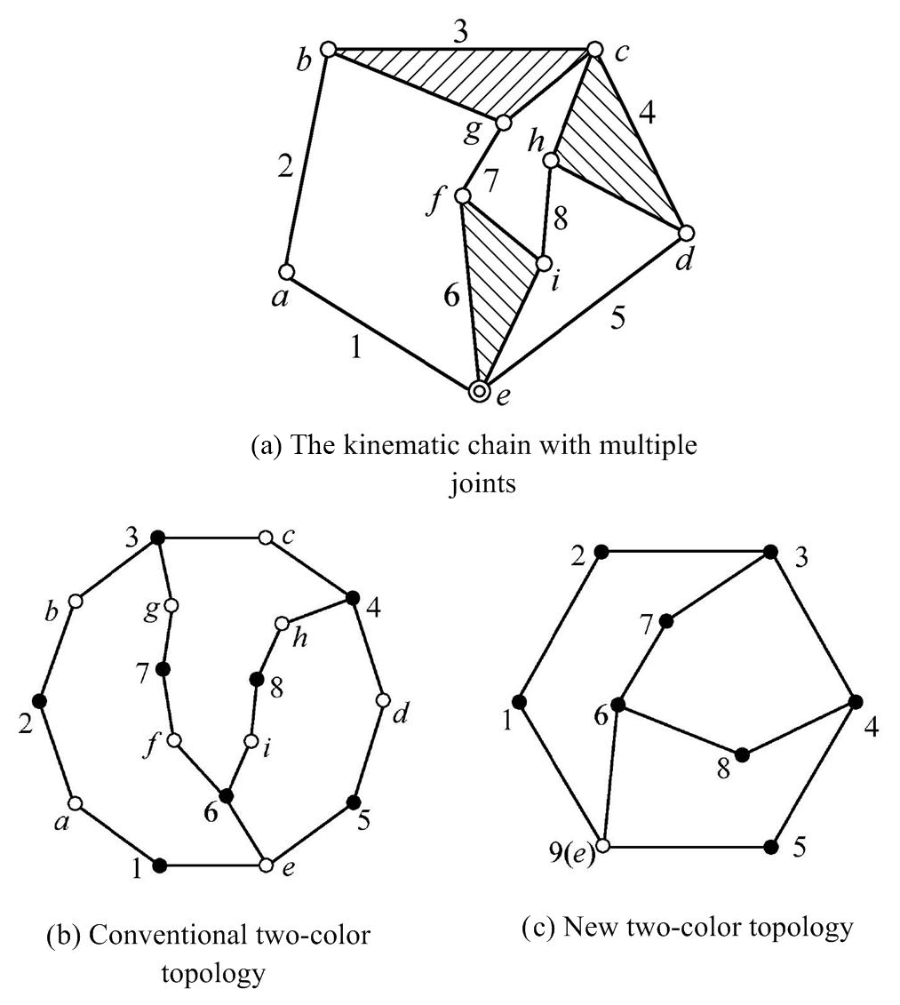
A number of methods have been developed to describe the topological structure of metamorphic mechanisms. For instance, topological graph and matrix representation can be widely used in the field of mechanism analysis, kinematic chain synthesis, isomorphic identification and topological structure generation of metamorphic mechanisms. The expression of multiple joints is always a difficult problem as shown in Fig. 1. Ding et al. (2009, 2010, 2013) proposed a new kind of bicolor topological graph to represent the topological structures of multiple joint kinematic chains. Represent links of kinematic chains with solid vertices “•” and hollow vertices “∘” denote joints as shown in Fig. 1b, and then remove hollow vertices “∘” denote simple joints as shown in Fig. 1c.
At present, the matrix that represents the configuration changes of metamorphic mechanism includes adjacency matrix and incidence matrix (Akbari et al., 2009). The EU elementary matrix is used to describe the transformation of metamorphic mechanisms. The adjacency matrix method and the incidence matrix method describe the matrix operation of the configuration transformation in metamorphic mechanisms clearly and they are beneficial to the realization of computer automation. However, it cannot fully express the size structure, kinematic pairs and other information. The description of the metamorphic mechanisms in sub-configurations is not comprehensive. This paper introduces a holographic matrix representation for describing the topological structure of metamorphic mechanisms. And the structural information can be described accurately and distinctly. The structural description of the metamorphic mechanism is an important part of kinematics and dynamics analysis.
2.1 The holographic matrix
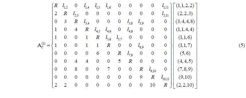
When using a computer to simulate a mechanism, it is only necessary to know the coordinates of the joints in the mechanisms. Therefore all the structural information of the mechanisms is known and schematic diagram of the mechanism can be drawn. Based on this idea, a holographic matrix was proposed. The size of the matrix is n×n. n is the number of joints of a kinematic chain. The holographic matrix in configuration m and expresses it as following:
Where, the diagonal element Ji of the matrix A represents the kinematic pair connecting two adjacent links in joint i, such as prismatic pair P, revolute pair R, spherical pair S. The element of the upper triangular matrix denotes the distance between two joints, which is the length of the two joints on the link corresponding to the link number in the element . The element of the down triangular matrix is the serial number of the link between joint i and joint j in the mechanism. If there is no actual link exists between joint i andj, the element is .
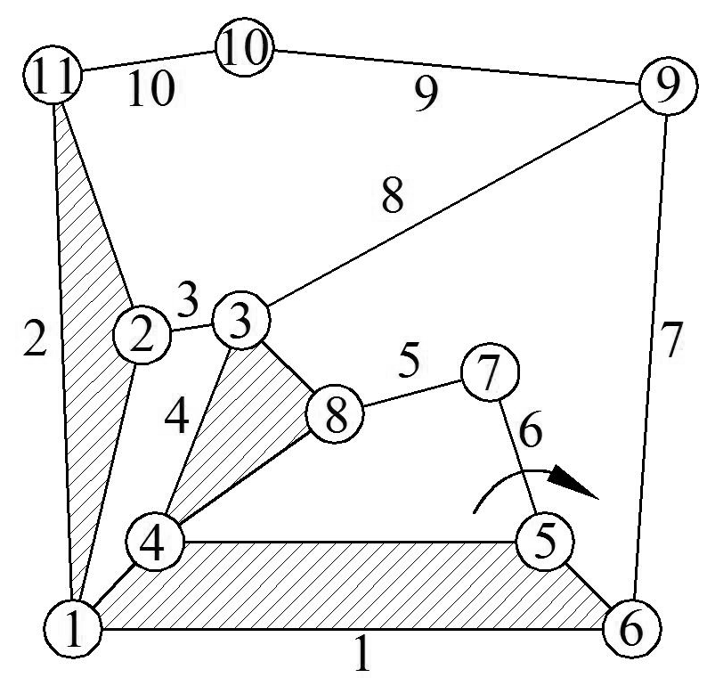
The serial number of links and kinematic pairs in 10 bar kinematic chain with multiple joints is expressed as shown in Fig. 2. The holographic matrix of 10 bar kinematic chain C is expressed as:
2.1.1 Including the adjacency matrix and incidence matrix
The adjacency matrix is the matrix of the adjacent relations between vertices, representing the relationship between kinematic pairs and links. The element value of the non-zero is converted to ”1”. Diagonal elements are omitted. The adjacency matrix BC can be obtained.
The incidence matrix is a matrix representing the relationship between each vertex and each edge. The holographic matrix contains the serial number of links and kinematic pairs, which implied the relationship between links and joints. So the incidence matrix CC is expressed as.
Where, the row number of the incidence matrix CC is the serial number of links and the column number is the serial number of kinematic pairs. The incidence matrix CC of the kinematic chain C can be obtained by searching the holographic matrix AC. For instance, ninth row (or ninth column) of the holographic matrix represents the connection relationship between the kinematic pair 9 and other links. So the link 7, link 8 and link 9 be connected to the kinematic pair 9.
2.1.2 Including kinematic pairs information
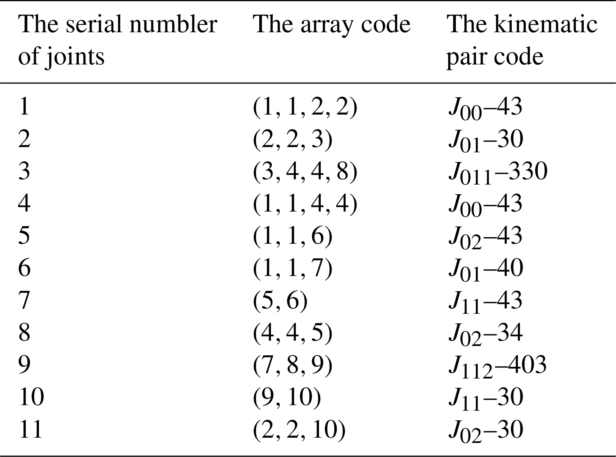
The number of non-zero and unequal values in the i row element and i column element is k. If k=2, the joint i is a simple joint. If k≥3, the joint i is a k element multiple joints. For instance, there are two unequal values “2, 3” in the second row and the second column of the holographic matrix AC, we can determine the joint J2 is a simple joint. Similarly, the joint J3 contains three unequal values “3, 4, 8”, so this joint a ternary multiple joints.
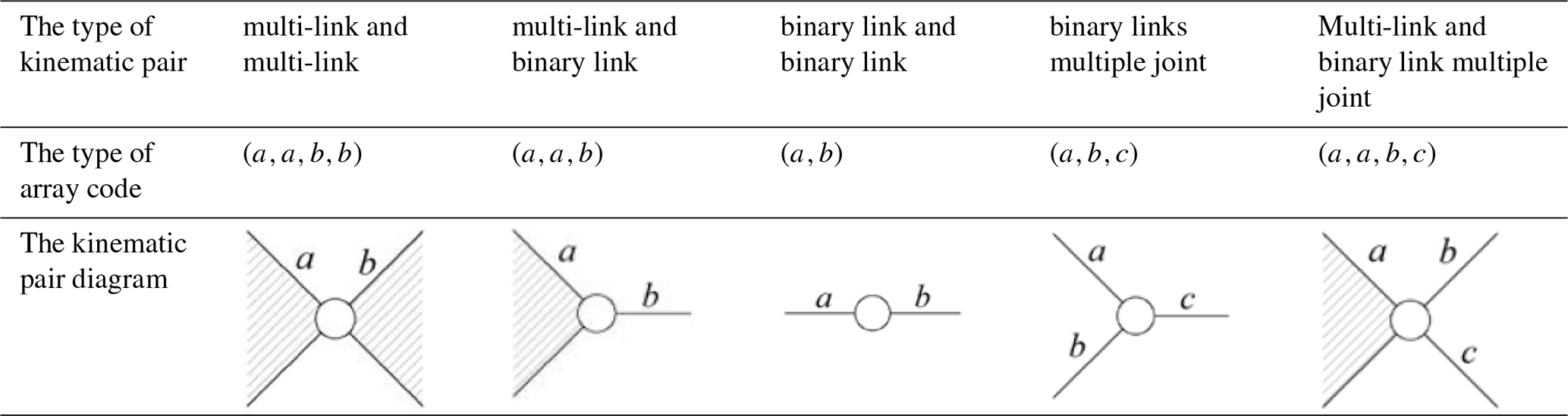
The relationship between the two links can be divided into multi-link and multi-link, multi-link and binary link, binary link and binary link by the inductive method. If it's a multiple joints, it's a combination of conditions. The holographic contains the connection relation of the kinematic pairs, which is not available in other matrices.
 The array codes of the matrix are obtained by generalized operations on the
i row and i column elements corresponding to the joint Ji eliminated zero elements and
kept the non-zero elements. If same non-zero elements appear more than twice
only two of them are kept. Array codes for each kinematic pair corresponding
to the joints are shown in Eq. (5). The value of array codes are
arranged from small to large. Analyzing each array code, the table on the
type of kinematic pairs corresponding to array code can be obtained as
showed in Table 1.
The array codes of the matrix are obtained by generalized operations on the
i row and i column elements corresponding to the joint Ji eliminated zero elements and
kept the non-zero elements. If same non-zero elements appear more than twice
only two of them are kept. Array codes for each kinematic pair corresponding
to the joints are shown in Eq. (5). The value of array codes are
arranged from small to large. Analyzing each array code, the table on the
type of kinematic pairs corresponding to array code can be obtained as
showed in Table 1.
Table 1The type of kinematic pairs.
Note: the type of multiple joint cancontain more links, the number of array code can continue to increase.
In array code, the serial number of the same link appears twice, which expresses the link is multi-link. And the serial number appears only once, which expresses the link is a binary link. The different serial number in array code indicates the different links are connected to this joint. For example, the array code means multi-link a, binary link b and binary link c connecting in this joint.
In order to represent the connection between kinematic pairs better, the kinematic pair code Jxx–xx indicated the attribute of a kinematic pair is proposed. The meaning of its symbol is as following:
-
The size of the subscript array expresses the number of links in the kinematic pair. For example, the array code of the joint J1 means link 1 and link 2 are connected in this point, so the size of the subscript array in the point J1 is 2.
-
The value of the subscript array indicates the number of series binary link in a kinematic pair. The values in the subscript array are arranged from small to large. When multi-link is connected to multi-link, the value is “0”. For example, the link 1 is quaternary link and link 6 is binary link connected in the joint 5. Then the link 6 is connected to binary link 5 and the link 5 is connected to the ternary link 4. The number of series binary link is 2. So the value of the subscript array is “02”.
-
The subsequent array corresponds to the subscript array. The size of subsequent array is equal to the subscript array. But the value of subsequent array represents the type of the link at the end of the binary link. If the numbers of series binary link are the same, the value of the subsequent array arranges from large to small. For intance, the link 1 in the joint 5 is quaternary link, so the value corresponding to the subsequent array is “4”. The type of the link at the end of the binary link 6 is ternary link 4, so the value corresponding to a subsequent array is “3”. Therefore, the value of subsequent array is “43”.
-
If the type of the link at the end of the binary link is multiple joints, the value corresponding to subsequent array is “0”.
The kinematic pair code can be obtained by retrieving the array codes. For instance, the array code of the joint 3 is , and the type of the link at the end of the binary link 3 is ternary link 2, and the type of the link at the end of the binary link 8 is a ternary multiple joint. The kinematic pair code in the joint 3 is J011–330. Thus, the table of the kinematic pair code be obtained as showed in Table 2.
2.1.3 Including the links information
The serial number of links in the i row element and i column element of the holographic matrix corresponding to the joint Ji appears k−1 times. For example, if the link is binary link, the serial number of the link in the i row element and i column element corresponding to the joint Ji appears 1 time. If the link is a ternary link, the serial number of the link appears 2 times.
The attribute of the links with kinematic pair information is represented by Ni–xxx. Ni expresses the link is i element multiple links. The subsequent array indicates the connection of this link and binary link. Its rules are:
-
The size of the subsequent array is equal to the elements of the link. For example, the attribute of the ternary link N3 with three digital numbers is represented as N3–xxx.
-
The value of the array indicates the number of series binary link. When multi-link is connected to multi-link, the value is “0”. The value of the array arranges from small to large.
-
For the joint connecting to multi-link is a multiple joint, and the multiple joint is treated as a multi-link, indicated by the value “-1”.
The attribute of the links with kinematic pairs of a kinematic chain C is shown in Table 3.
Table 3The attribute of the links.

Note: Ni expresses the link is i element multiple links.
2.1.4 Including the links length information
The element li,j of the upper triangular matrix is the length of link. If the link is a binary link, the value is the length at both ends of the joints. If the link is k(k≥3) element multiple link, the number of the elements of the upper triangular matrix corresponding to the link is , which represents the number of between any two joints of a multiple link. The number of the length in a ternary link is 3. The number of the length in a quaternary link is 6 including four outer edges and two diagonals. The geometry of the quaternary link is determined. The structural dimensions of the multiple links can always be determined based on the length of the links in the holographic matrix. Thus, the element of the upper triangular matrix contains the geometric information of all the links in the mechanism.
2.2 The expanded holographic matrix
Some parameters must be given when the topological structure changes in the design of metamorphic mechanism. At the same time, the change of topological structure may lead to the change of the degree of freedom of the mechanism. It must be given new parameters of the driving link, or remove the parameters of the failed driving link. So the expanded holographic matrix is proposed based on the holographic matrix. Expressed as in Eq. (6).
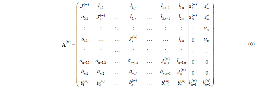
The n+1 column element of expanded holographic matrix includes the serial number of the frame link and driving link. The n+2 column element includes initial position (initial angle) sλ, stop position (stop angle) sμ, velocity (angular velocity)ν, accelerated velocity (angular accelerated velocity)α. In order to record the sequence of the transformation better, a row is added to the expanded holographic matrix. The element is the identifier of the joint j in configuration m. The element expresses the identifier of the frame link in configuration m. The element expresses the identifier of the driving link in configuration m. The value also changes along with the configuration variation of metamorphic mechanism with kinematic pair, frame and driving link.
The holographic matrix is used to describe the topological structure of the metamorphic planar mechanism. When the link sequence and the joint sequence are determined, a definite unique holographic matrix is obtained. The structure of the metamorphic mechanism can be obtained from the holographic matrix as well. For instances, a packaging mechanism is designed using the metamorphic principle which is a recirculating metamorphic mechanism as showed in Fig. 2. The main features of the mechanism are topological structure continues to change during the cycle of the driving link works and continues to occur and repeat the same function of the cycle changes.
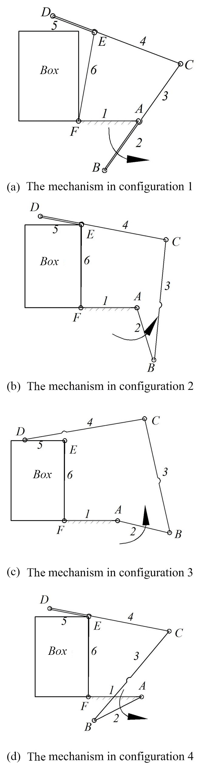
From Fig. 3, it can be concluded that the topological structure of the mechanism can be transformed from one to another by locking at different kinematic joints accordingly. By applying modes such as the geometric limit, force limit, and variation of the driving kinematic joint, the working conditions of these kinematic joints can be switched between active and locked states. Therefore, it is very important to accurately describe the process of reconfiguration in metamorphic mechanisms. The holographic matrix shown in Eq. (6) is used to represent the various configurations of the packaging mechanism in Fig. 3.
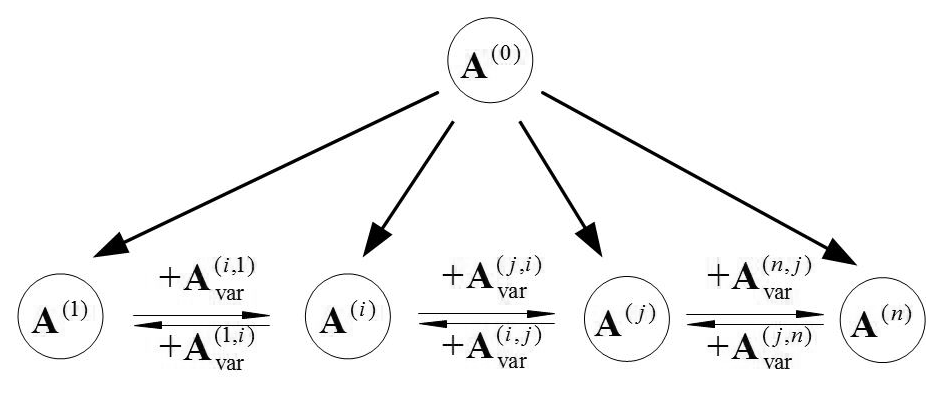
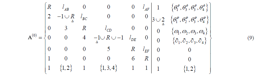
A holographic matrix representation for describing the topological structure of metamorphic mechanisms in a single configuration is introduced. However, exploring variation laws of these mechanisms in different configurations is very important for developing novel metamorphic mechanisms (Zhang et al., 2016). The advantage of matrix operations is taken for constructing the original metamorphic mechanism.
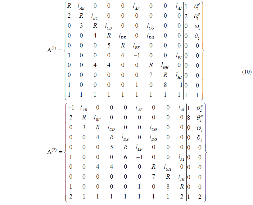
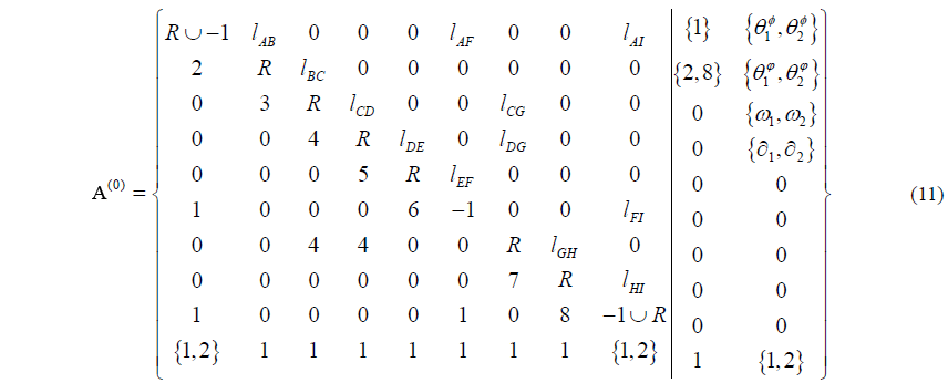
The original metamorphic mechanism is able to evolve into any configuration of the mechanism and contains all the topological elements found in all sub-configurations. An original matrix A(0) for representing the original metamorphic mechanism is given as in Eq. (8). Where, the operator ∪ represents the union of its arguments (Zhang et al., 2016). The original matrix A(0) has the same elements form as Eq. (6). All the elements located in the same position in the set of related matrices from A(1) to A(n) gradually become united as shown in Eq. (8). Therefore, the matrix of the original metamorphic mechanism for the packaging mechanism shown in Fig. 2 is as in Eq. (9).
The matrix can identify all possible combinations between links for creating different mechanisms. The original metamorphic mechanism can evolve into any topological structure of the metamorphic mechanism. The transformation of a single structure of the metamorphic mechanism can also be operated. The relationship between the various matrices can be expressed. Therefore, the information on the mechanism in configuration m can be extracted from the matrix A(0) to construct the corresponding matrix A(m). For example, the elements marked by triangles Δ in Eq. (9) are extracted to construct the matrix A(2). The topological structure of the mechanism in configuration 2 according to the above procedure was represented in Eq. (7).
An original metamorphic mechanism provides a foundation for a mechanism to transform itself into any configuration and expresses the joint variation characteristics from the symbolic adjacency matrices and the corresponding operations. The relationships between these matrices are as shown in Fig. 4.
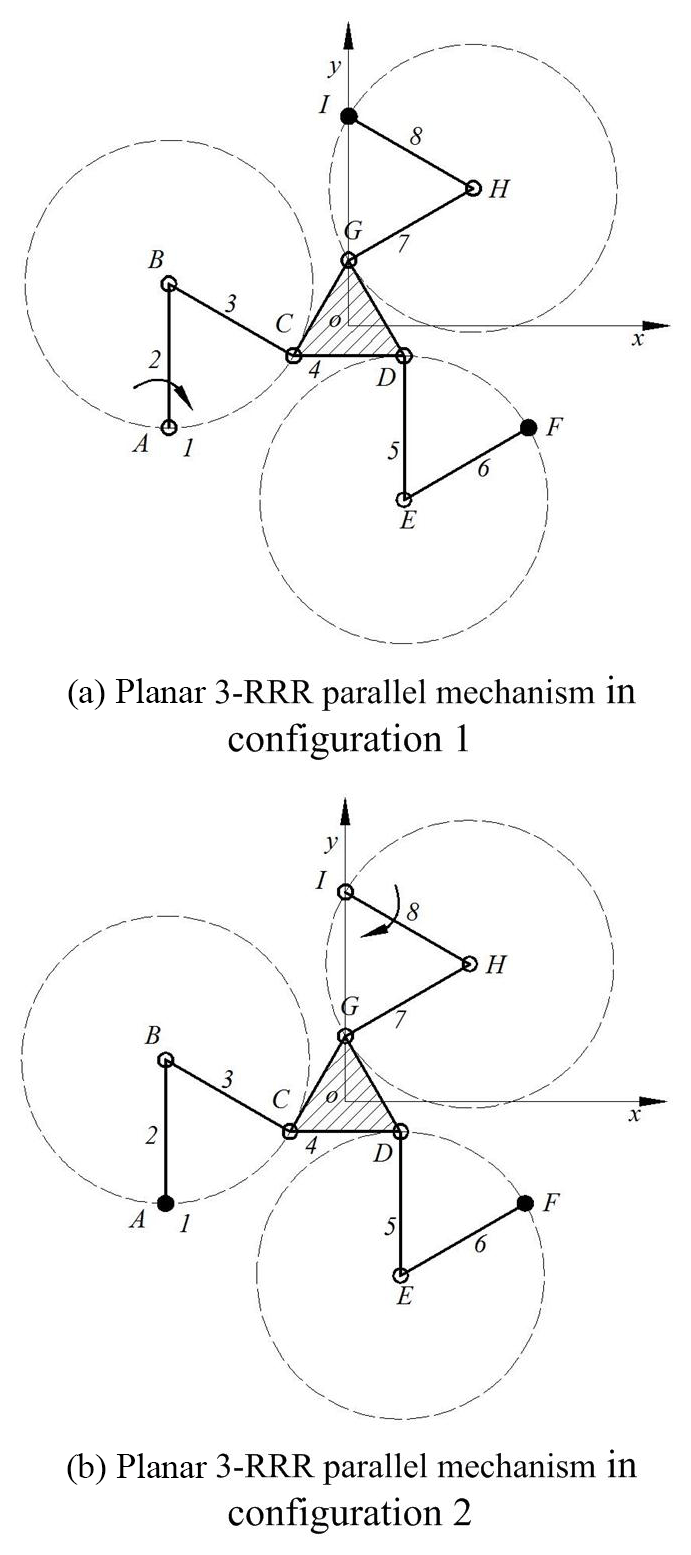
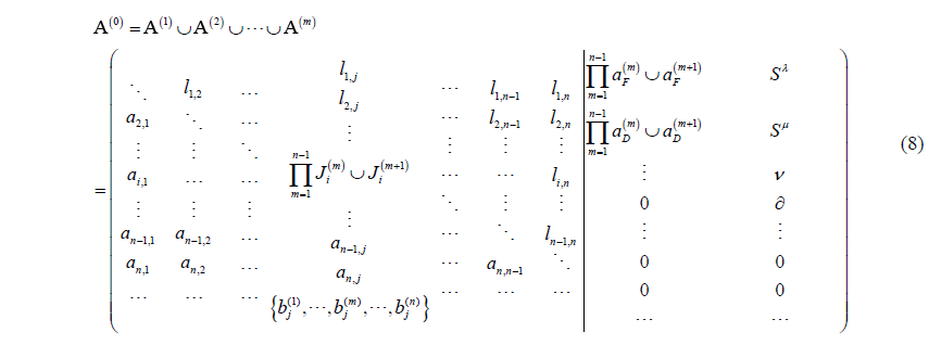
A planar 3-RRR parallel mechanism is shown in Fig. 5. All R joints of the mechanism are in parallel.
The metamorphic mechanism has two configurations. When the mechanism is in configuration 1 as shown in Fig. 4a, the revolute pair F and the revolute pair I are locked. The link 1 is frame link. And the link 2 is the driving link. When the mechanism is in configuration 2 as shown in Fig. 5b, the revolute pair A and the revolute pair F are locked. The link 1 is always frame link. But the link 8 is the driving link. The topological structures of the metamorphic mechanism can be expressed in matrix form as in Eq. (10).
The serial number 4 appears twice in joint 3 or joint 7. Then it can be judged that the link 4 is a ternary link. The original matrix of the original metamorphic mechanism can be expressed as Eq. (11).
The value of the element A(0)(9,9) in matrix represents the revolute pair I has been changed. The value of the element A(0)(2,10) in the original matrix {2,8} explains the driving link has been changed.
An expanded holographic matrix was proposed to describe the topological structure of the metamorphic mechanism in this paper. The expanded two columns of the matrix are the property of the frame link and driving link. That is an indispensable part of information in the metamorphic mechanism. In addition, the upper triangular matrix denotes the distance between any two joints. It is very important for the kinematics analysis and dynamics analysis of the metamorphic mechanism in the next step. The down triangular matrix is the serial number of the links in the kinematic chain. This implies a lot of information including the adjacency matrix, incidence matrix, links attribute and kinematic pairs attribute. And the accurate judgment for multiple links and multiple joints is given by the serial number of the links. Finally, an example shows that this method can reflect the effectiveness of the metamorphic mechanism.
The data required to reproduce these findings are available to download from https://data.mendeley.com/datasets/s3w942ddrs/1 (last access: 8 August 2019).
WS and LS designed the matrix; JK analyzed experimental results. WS wrote the manuscript.
The authors declare that they have no conflict of interest.
This work is partially supported by the National Natural Science Foundation of China under Grant (No. 51875418).
This research has been supported by the National Natural Science Foundation of China under Grant (grant no. 51875418).
This paper was edited by Doina Pisla and reviewed by Daniel Condurache and one anonymous referee.
Akbari, S., Moazami, F., and Mohammadian, A.: Commutativity of the adjacency matrices of graphs, Discrete Math., 309, 595–600, 2009.
Dai, J. S. and Rees John, J.: Mobility in metamorphic mechanisms of foldable/erectable kinds, J. Mech. Des.-T. ASME, 121, 375–382, 1999.
Dai, J. S. and Rees John, J.: Matrix representation of topological changes in metamorphic mechanisms, J. Mech. Design, 127, 837–840, 2005.
Dai, J. S., Ding, X., and Wang, D.: Topological changes and the corresponding metrix operations of a spatial metamorphic mechanism, Chi. J. Mech. Eng., 41, 1–10, 2005.
Ding, H., Zhao, J., and Huang, Z.: Unified Topological Representation Models of Planar Kinematic Chains, J. Mech. Design, 131, 114503, https://doi.org/10.1115/1.4000215, 2009.
Ding, H., Zhao, J., and Huang, Z.: Unified structural synthesis of planar simple and multiple joint kinematic chains, Mech. Mach. Theory, 45, 555–568, 2010.
Ding, H., Yang, W., Huang, P., and Kecskeméthy, A.: Automatic Structural Synthesis of Planar Multiple Joint Kinematic Chains, J. Mech. Design, 135, 1–12, 2013.
Ding, X. and Li, X.: Design of a type of deployable/retractable mechanism using friction self-locking joint units, Mech. Mach. Theory, 92, 273–288, 2015.
Gan, D., Dai, J. S., and Liao, Q.: Mobility Change in Two Types of Metamorphic Parallel Mechanisms, J. Mech.Robot., 1, 041007, https://doi.org/10.1115/1.3211023, 2009.
Gan, D., Dai, J. S., and Liao, Q.: Constraint analysis on mobility change of a novel metamorphic parallel mechanism, Mech. Mach. Theory, 45, 1864–1876, 2010.
Lan, Z. H. and Du, R.: Representation of Topological Changes in Metamorphic Mechanisms With Matrices of the Same Dimension, J. Mech. Design, 130, 074501, https://doi.org/10.1115/1.2918917, 2008.
Li, D., Zhang, Z., and Chen, G.: Structural Synthesis of Compliant Metamorphic Mechanisms Based on Adjacency Matrix Operations, Chin. J. Mech. Eng., 24, 522–528, 2011a.
Li, D., Zhang, Z., and Mccarthy, J. M.: A constraint graph representation of metamorphic linkages, Mech. Mach. Theory, 46, 228–238, 2011b.
Li, S. and Dai, J.: Augmented Adjacency Matrix for Topological Configuration of the Metamorphic Mechanisms, J. Adv. Mech. Des. Syst., 5, 187–198, 2011.
Li, S., Zhang, Y., Yang, S., and Wang, H.: Joint-gene based variable topological representations and configuration transformations, Asme/iftomm International Conference on Reconfigurable Mechanisms and Robots, IEEE, London, 348–354, 2009.
Li, S., Wang, H., Meng, Q., and Jian, S. D.: Task-based structure synthesis of source metamorphic mechanisms and constrained forms of metamorphic joints, Mech. Mach. Theory, 96, 334–345, 2016.
Liu, J.: Metamorphic Equation of Variable Topology Mechanisms Based on the Constraint function, J. Mech. Eng., 48, 1–9, https://doi.org/10.3901/jme.2012.09.001, 2012.
Ye, W., Fang, Y., Zhang, K., and Guo, S.: Mobility variation of a family of metamorphic parallel mechanisms with reconfigurable hybrid limbs, Robot. Clim.-Int. Manuf., 41, 145–162, 2016.
Zhang, K., Dai, J. S., and Fang, Y.: Geometric Constraint and Mobility Variation of Two 3Sv PSv Metamorphic Parallel Mechanisms, J. Mech. Design, 135, 011001, https://doi.org/10.1115/1.4007920, 2013.
Zhang, L. and Dai, J.: Reconfiguration of Spatial Metamorphic Mechanisms, J. Mech. Robot., 1, 011012, https://doi.org/10.1115/1.2963025, 2009.
Zhang, W., Ding, X., and Liu, J.: A representation of the configurations and evolution of metamorphic mechanisms, Mechanicalences, 7, 39–47, 2016.