the Creative Commons Attribution 4.0 License.
the Creative Commons Attribution 4.0 License.
 | 11 Jul 2019
Development of a novel flapping wing micro aerial vehicle with elliptical wingtip trajectory
Qiang Liu
Qiang Li
Xiaoqin Zhou
Pengzi Xu
Luquan Ren
Shengli Pan
This paper describes a novel flapping wing micro air vehicle (FWMAV),which can achieve two active degree of freedom (DOF) movements of flapping and swing, as well as twisting passively. This aircraft has a special “0” figure wingtip motion trajectory with the 140∘ flapping stroke angle. With these characteristics integrated into the simple flapping mechanism, the aerodynamic force is somewhat improved. The model made a balance between the improved aerodynamic performance induced by complicated movements and the increased weight of the extra components in aircraft. In the driven design, Only one micro-motor is employed to drive the wing flapping and swing motion simultaneously forming the prescribed trajectory. The 23 g aircraft could reach the maximum flapping frequency of 11 Hz with the tip-to-tip wingspan of 29 cm.


Since reported in 1990s, plenty of flapping wing micro air vehicles (FWMAVs) designed to imitate a flying insect or a bird with small size and flexible wings have been attracting lots of interest (Mcintosh et al., 2006; Shyy et al., 2010; Nguyen et al., 2010). The follow-up studies showed that flapping MAVs have greater advantages over fix wing and rotary wing MAVs in maneuverability, concealment, microminiaturization and effectiveness under low Reynolds number circumstance. Due to the favorable potentialities, FWMAVs could be widely applied in the fields of military reconnaissance, surveillance, geological exploration, hazardous environment exploration and so on (Keennon and Grasmeyer, 2003). Plenty of expenditure have been invested by government to support FWMAV research in many countries, and many successful efforts in FWMAV have already been made, such as the studies of insect aerodynamic characteristics, flexible wing kinematics and FWMAV mechanism design.
The flapping wing mechanism of micro air vehicle is the basic work for developing FWMAVs. Through the work of Ellington and Dickinson, the complex aerodynamics of a periodic flapping stroke at low Reynolds numbers is well introduced to be a design tool for engineers to create flapping devices (Ellington et al., 1996; Ellington, 1999; Dickinson et al., 1999; Birch and Dickinson, 2001). These researchers are dedicated to study the flapping wing aerodynamics that provide theoretical guidance to the designers to develop new type FWMAVs. These research verified that multi-degree-of-freedom (DOFs) flapping movement of the wing can generate better aerodynamic performance than single-DOF flapping movement. Accordingly, kinds of successful flying FWMAVs are developed.
Microbat is the first electrically powered palm-sized ornithopter by University of California. The key technology of Microbat is the MEMS wings which enabled the prototype to perform better in terms of repeatability, size control, weight minimization, mass production, and fast turnaround time during flapping (Pornsin-Sirirak et al., 2001). Harvard University's Microrobotic Fly is a real insect-sized flapping wing micro air vehicle. It was driven by a high energy density piezoelectric actuator, which was much smaller compared with other flapping prototype actuators. The total weight of Microrobotic Fly is 60 mg with the wingspan of 3 cm, and the rather remarkable wingbeat frequency is 110 Hz (Pornsin-Sirirak et al., 2000; Pérez-Arancibia et al., 2011). The Festo Company developed a large-size aircraft named Bionic Flying Fox with the mass of 580 g and wingspan of 228 cm which can fly freely in several flight models. As with the biological model, all the articulation points are on one plane, meaning that the Bionic Flying Fox can control and fold its wings together individually (BionicFlyingFox, 2018). From the above mentioned, it can be seen that design rules of FWMAVs has been well studied and many multi-DOF prototypes have been developed. However, these multi-DOF FWMAVs usually consist of several motors and complex transmission mechanism resulting in large mass so that they need larger wingspan to generate enough power. Besides, the small sized single-DOF FWMAVs driven by piezoelectric actuators or other new actuators cannot fly freely (Finio et al., 2009; Bejgerowski et al., 2009; Rue et al., 2013; Au et al., 2016). In nature, the flyer basic motions are combined by flapping, twist and swing. While it is difficult to imitate the exact flight model of natural flyers with suitable small-sized mechanism, it is a good choice to implement two flight models with high level lift and high energy efficiency.
FWMAVs whose wings can generate out-of-plane flapping and twist motion have already occupied for a large proportion (Yang et al., 2009; Weintraub et al., 2015; Young et al., 2009), while the flapping mechanism of flapping and swing motion are seldom reported. The reason maybe is that wing twist is more important in aerodynamic performance than swing motion. However, for natural flyers, the motion of wing swing could change the direction of instantaneous velocity and the deformation amplitude of wings during upstroke and downstroke, and the total thrust force could be somewhat strengthened (Zbikowski, 2002; Lehmann, 1998; Ellington, 1984; Weisfogh, 1973). The wing flapping amplitude is also an important factor to affect the aerodynamic force. According to Pérez-Arancibia et al. (2011), the estimated mean total lift force directly depends on the wing flapping stroke amplitude and the flapping frequency regardless of the size and shape of the wing. This indicates that flying insects and birds can modulate the average lift force by changing the flapping amplitude. In fact, natural flyers mostly have a large flapping angle to increase aerodynamic forces. Due to the limit of narrow space of mechanism, many multiDOF prototypes could not achieve flapping motion with a flapping stroke angle more than 70∘, which were smaller compared to the stroke angle of 120∘ of some birds and insects (Ryan and Su, 2012). Therefore, the design of integrating wing swing motion and large flapping angle into FWMAVs can improve flying performances, and it is helpful to provide an opportunity to study the effect of large flapping angle and wing swing of the natural flyers.
Along to the thinking line mentioned above, this paper developed a new type FWMAV whose wing has swing motion with a large flapping angle. The wing tip trajectory of the novel aircraft is a spatial “0” figure which is similar with some flying insects such as cicadas. The aircraft is driven by a simple mechanism composed of one micro-motor and a two-stage gear reducer. The advantage of this mechanism is that the major axis of “0” figure wingtip trajectory can be adjusted to achieve different flying path. The mechanical design and motion analysis are presented in Sect. 2, the flutter tests are carried out in Sect. 3 to study the performance of the new FWMAV.
2.1 Overall design of the aircraft
There seems no way but to design a complicated flapping mechanism to follow the multiple DOFs flapping trajectory like birds or insects for the artificial wing beating vehicles. In that classical thinking of mechanism design, a more complicated flapping mechanism usually means better performance in flexibility and maneuverability, but also means more weight which do great harm to the aerodynamic performance of MAVs, thus it was of vital importance to balance the complexity of the mechanism and total weight. As a result, the aircraft in this paper made a trade-off between the two sides.
Firstly, the actuator must be selected. Though there are many new types of actuators for flapping MAVs, traditional motors are still the most reliable technology and widely used. However, motor actuators typically occupy a large proportion in the total weight of aircrafts and adversely offset a part of the valuable lift generation. After weighing the pros and cons, the traditional actuator was accepted as the source of the rotary motion in our designed aircraft. Based on the approximate weight, flapping frequency, wing span and flying speed, a light weight commercial brushless motor (AP02, 2.3 g, 3.7 V, XIPHORIX) was selected. Then, a new mechanism associated with multiple slide joints and revolute joints was proposed based on the combination of a gear reducer system, a revolving crank and a coupler which can create a large flapping stroke angle and swing motion. The motor was fixed to the main airframe with three micro plastic screws. Considering the preset maximum flapping frequency and torque loading on the wings, the appropriate gear reduction ratio was chosen and some influence factors such as machining error and installation error were also taken into consideration. It can be described as the following equation:
Where igear, n0, η, and fmax are the gear reduction ratio, no-load rotation per minute, influential factor for rotation and maximum flapping frequency respectively. The performance parameter of the motor, rated speed n0 is 29 600 rpm. Due to the influence of loading on wings, resistance of components, machining and installation error, η is set as 0.7. fmax is no more than 12 Hz. With the relevant numerical value substituted, igear was about 28.778. As a result, igear was set as 27.6 according to the existing gears. These gears are made of polymer by injection molding process due to the complexity of the part shape and small size scales.
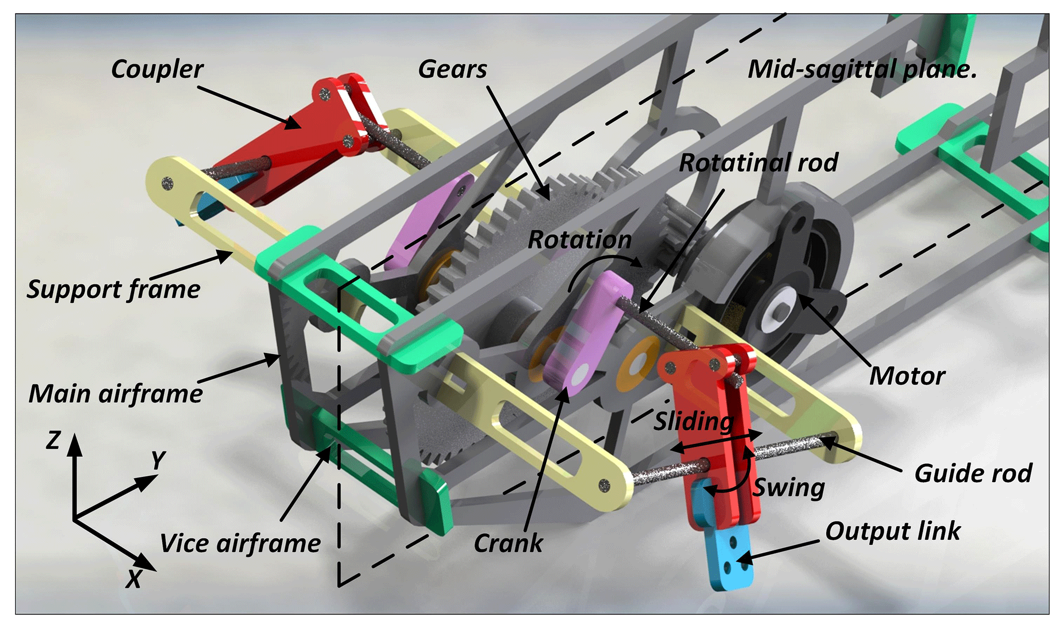
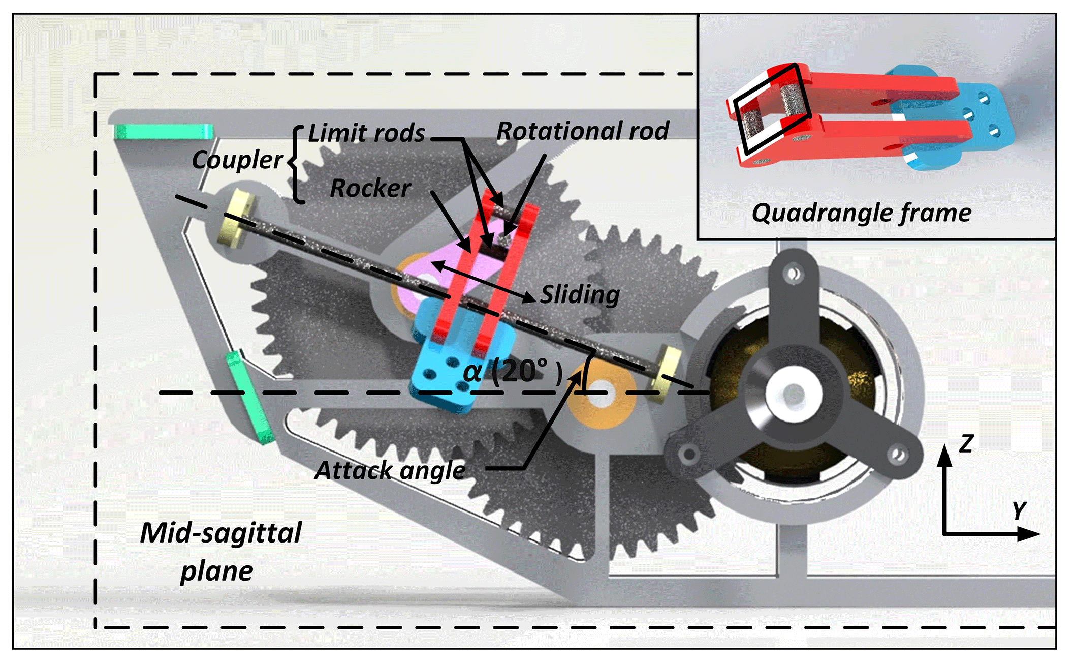
Figures 1 and 2 display the 3-D model and motion principle of the aircraft. The rotational motion of the cranks on both sides of the main airframe is fully synchronous, which means that other crank-driven components symmetric about the main airframe are all always remain synchronized about the mid-sagittal plane. The wing swing motion is implemented by the forth-and-back translational movement instead of swing around the wingroot. This motion model is kind of different from the natural flyers but the change increases the effect of inner wing part during swing. In this design, it is easy to adjust the wingtip trajectory when the wing swing amplitude is a constant value which does not change with the variation of wingspan. The motion principle of the new aircraft is presented as follows. The rotational rod, rigidly attached to the crank, pushes the coupler sliding along and revolving around the guide rod all the time when the mechanism works, and always remains perpendicular to the mid-sagittal plane of the aircraft. The coupler is composed of two exactly the same rockers, two limit rods and an output link, which form a quadrangle frame structure shown in Fig. 2. The rotational rod is inserted into the quadrangle frame structure and always keeps in contact with one edge of the frame. With this configuration, the rotational rod is able to extend and shrink, and revolve relatively to the position of quadrangle frame as the crank rotates. Compared to flexure hinges, the point and line contact form between the coupler and rotational rod reduces more weight and friction. When the rotational rod revolves around the output axis for a cycle, the coupler and its rigidly connected wing swing up and down around the guiding rod for one time; at the same time, the coupler and wing sweep forth and back along the guide rod. Therefore, with the two different types of coupler motion combined together, flapping and swing could be integrated into one wing at the same time, forming the spatial “0” figure motion trajectory.
2.2 Design calculation of flapping mechanism and kinematics of flapping motion
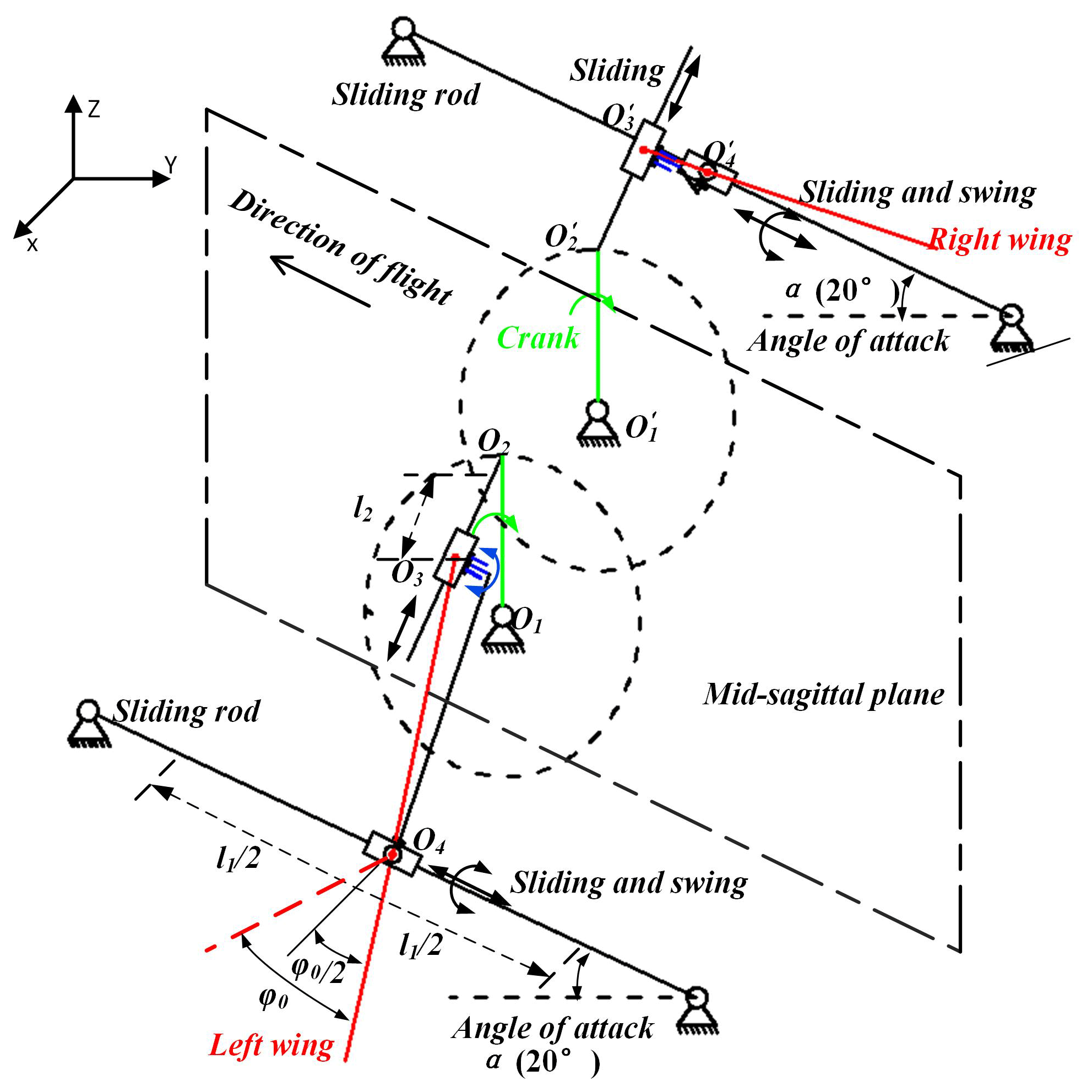
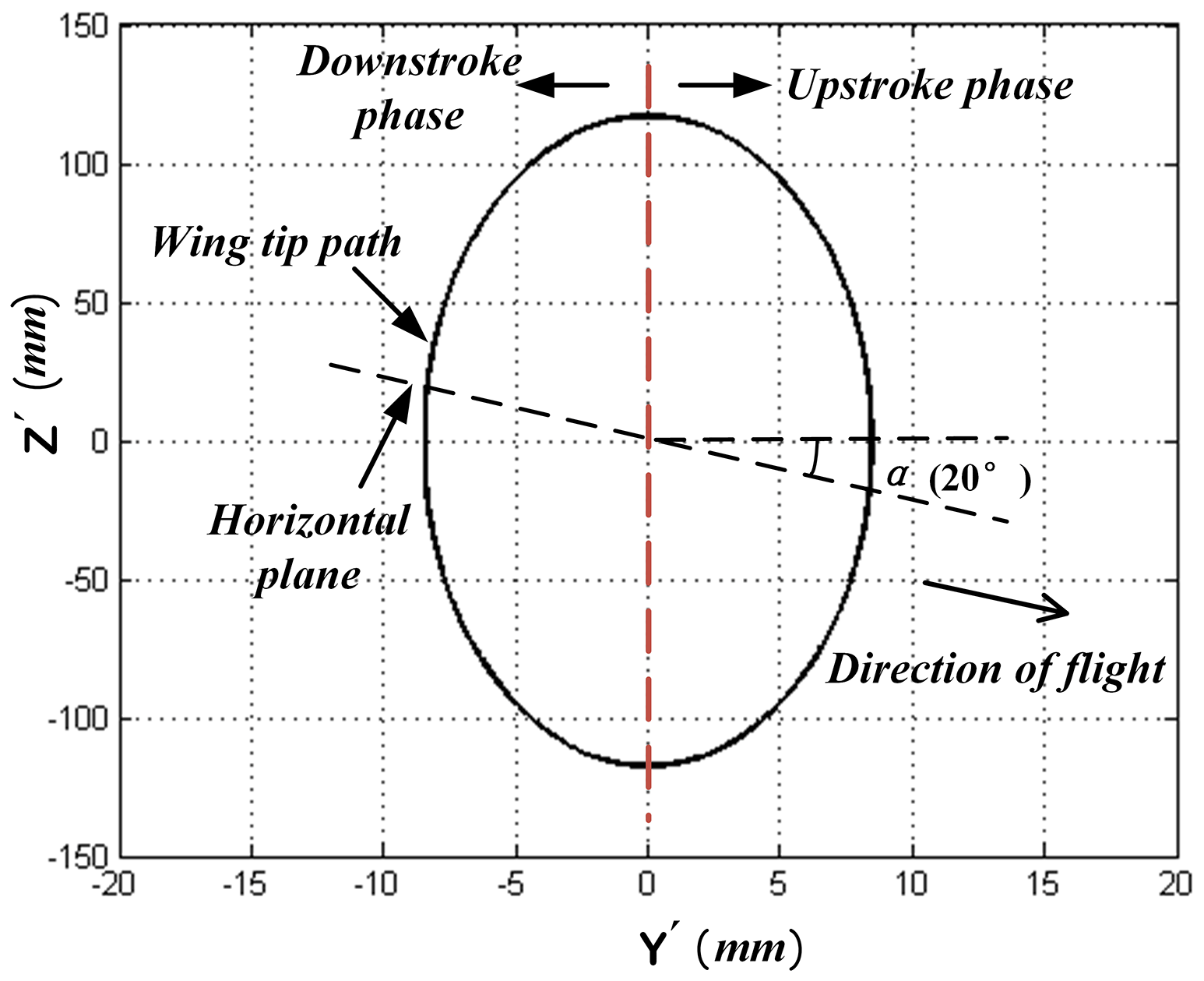
A new local three-dimensional cartesian coordinate system of wing is established and the midpoint of guiding rod is set as the origin of coordinate system in Figs. 3 and 4. The guide rod limits the displacement movement of the coupler in X-axis direction and the plane formed by the three points of O2, O3 and O4 is always parallel to the plane, thus the coupler can only revolve around the guide rod. Besides, the movement relationship of coupler and guide rod can also be simplified as the combination of a slide joint and revolute joint. Due to the limitation of spatial layout and the requirement of wing flow attachment, the angles of attack α is set as 20∘. The coupler was moved forcibly by rotational rod from one extreme position to the other. When the coupler moved passed the midpoint of guide rod, the wing tip reached the minimum speed in Z-axis direction. And the wing tip showed the maximum speed in the process of flapping when coupler tended to move to the midpoint from two extreme positions. As the rotational rod reached its position in Fig. 4, the wing tip was situated in the lower limiting position, where the wing ended the downstroke and began the upstroke. The relationship of coupler can be expressed as follows:
where l1 and r are the movable distance of the coupler along the guide rod and the length of the crank respectively.
The flapping stroke angle amplitude φ0 can be written as a function of coupler geometry and length of crank as follows:
By adjusting the length of crank and , the amplitude of the flapping stroke angle φ0 can be as large as 140∘.
As the mechanism was activated, the flapping angle φ could be changed over time, and expressed as follows:
where n and t are the rotating speed of crank and time. With the variation of flapping frequency, the rotating speed of crank n could be changed from 0 to 660 r min−1 by adjusting the control receiver.
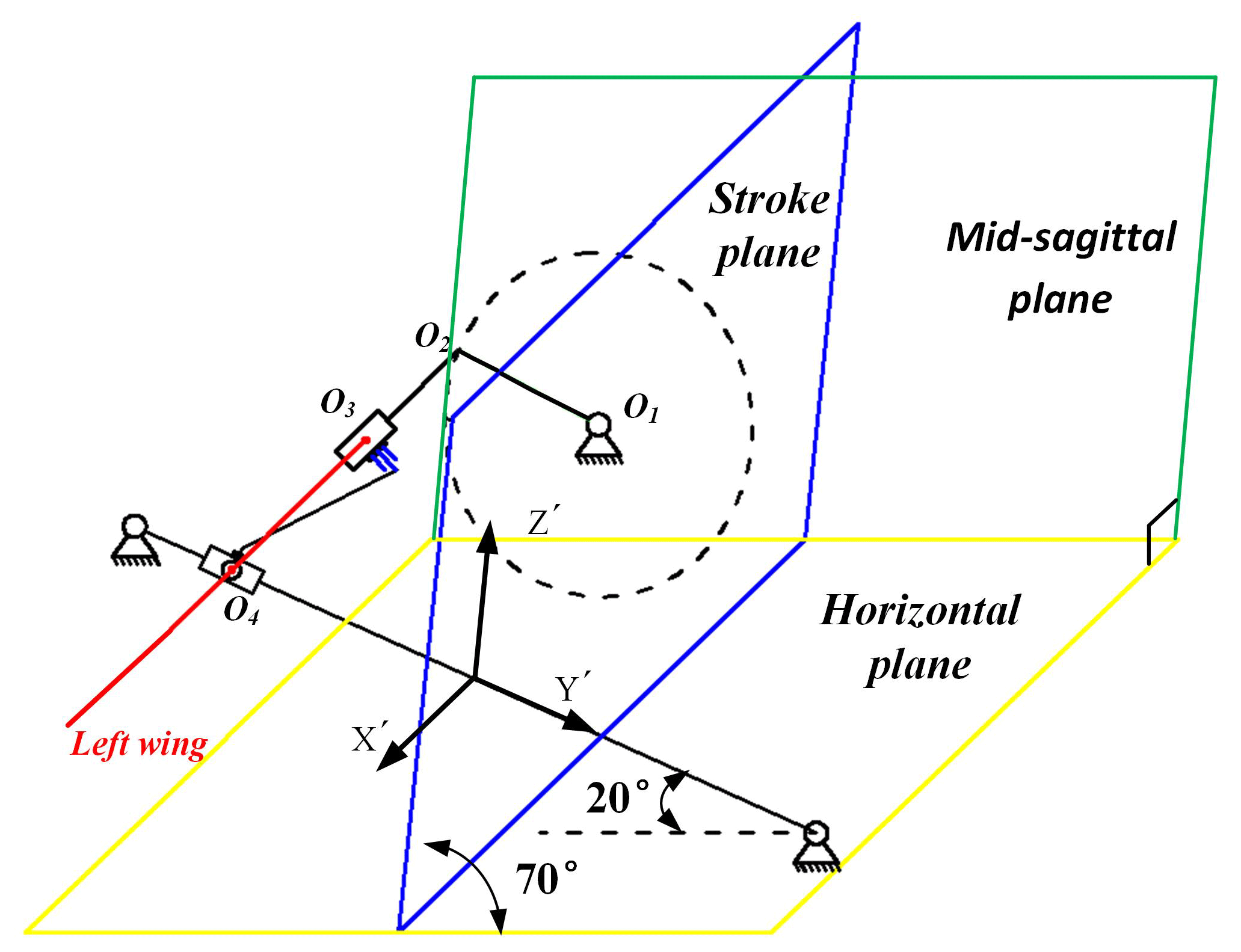
Based on geometry principle, the equations of motion for the coupler and wing along the coordinate axis in X′, Y′ and Z′ direction are established as follows:
where b is the distance from wing-tip to point O4.
The “0” figure motion trajectory in plane which is parallel with the mid-sagittal plane can be seen from the X′-axis and expressed as follows:
and the trajectory in three-dimensional space of wing-tip can be expressed as follows:
Figures 5 and 6 show the 2-D wing-tip path as seem from X′-axis direction and 3-D wing-tip path respectively.

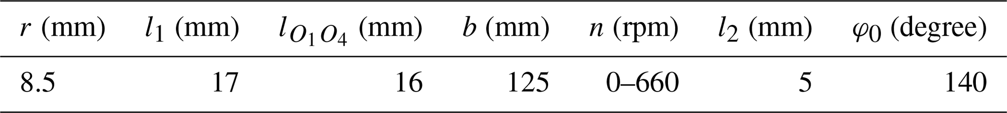
With software numerical simulation, empirical measurement and theoretical analysis, the specification of mechanism is determined and shown in Table 1.
2.3 Fabrication of the key component
The constraint on the weight of mechanism led us to choose carbon fiber as the material for the mechanism. By using a computer numerical control CNC machine (JingYan Instrument Company, CNC4030), we acquired and assembled the desired 2-D components of the flying prototype. Nevertheless, due to many slide joints and revolute joints existing in the mechanism, there was great friction loss when it worked. It should be noticed that though possesses good structure strength and low weight in the application of MAVs, carbon fiber lacks the ability to stand sustained abrasion especially for the incision surface. The coupler, a key part in the prototype made by the material of carbon fiber, appeared wear and tear when worked with the guide rod and rotational rod after a certain period of operation time. The issue of coupler affected the repeatability of mechanism and symmetry of wings, which impeded the smooth flapping and induced the corresponding unpredictable aerodynamic forces. To eliminate these issues, we remolded a prototype version with the new frames and coupler mentioned above, replaced the rotational rod and guide rod with the material of steel. Through test, the mechanism rendered us with better structural stiffness and operation life time, due to the low friction coefficient between steel and carbon fiber.
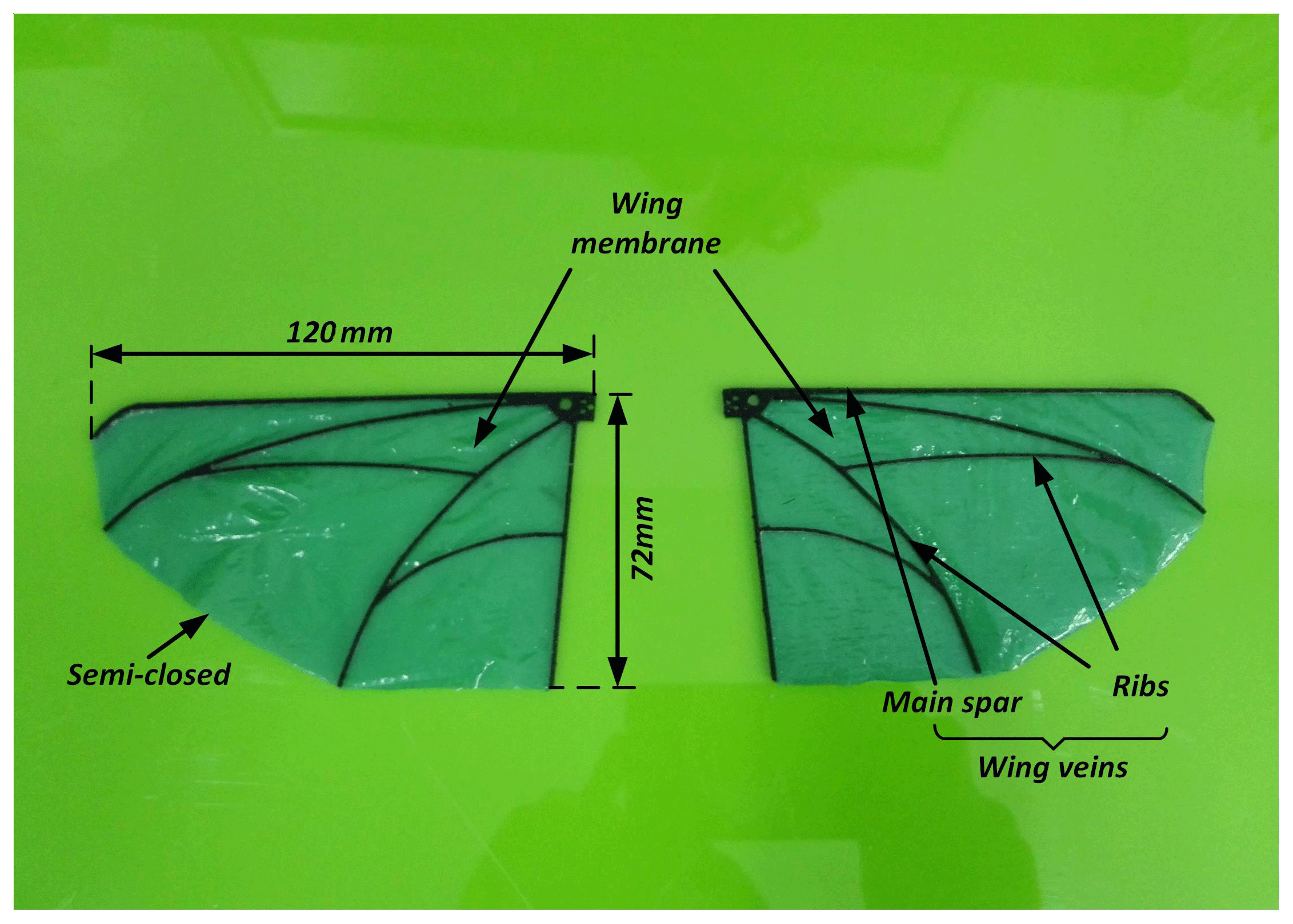
The airfoil including wing veins and membrane were designed to match the shape and layout of the wing of fruit flies (Hassanalian et al., 2017; Meng and Sun, 2016). Besides the characteristics of being light and strong, the airfoil has to be able to withstand high flapping frequency without breaking, and it also should be capable of generating enough lift and thrust to fly the prototype vehicles. The wing consisted of 0.5 mm thick ultrahigh modulus carbon fiber veins and 60 µm thick polyester membrane as shown in the Fig. 7. Due to the 2-D plane structure of main spar and ribs, the wing veins were very suitable for the CNC machining.
For the same size of wings, the wings with rigid leading edges produce larger lift coefficients compared to those with flexible leading edges (Pornsin-Sirirak et al., 2001). It should be mentioned that the airfoil in the paper was semi-closed for the part of trailing edge where the flexibility of the wing was increased compared to the closed structure. Besides, the vein of the leading edge was strengthened in width. Thus, the wings have the characteristic of rigid leading edges and soft, flexible trailing edges, which accords with high lift mechanism.
3.1 Experiment system
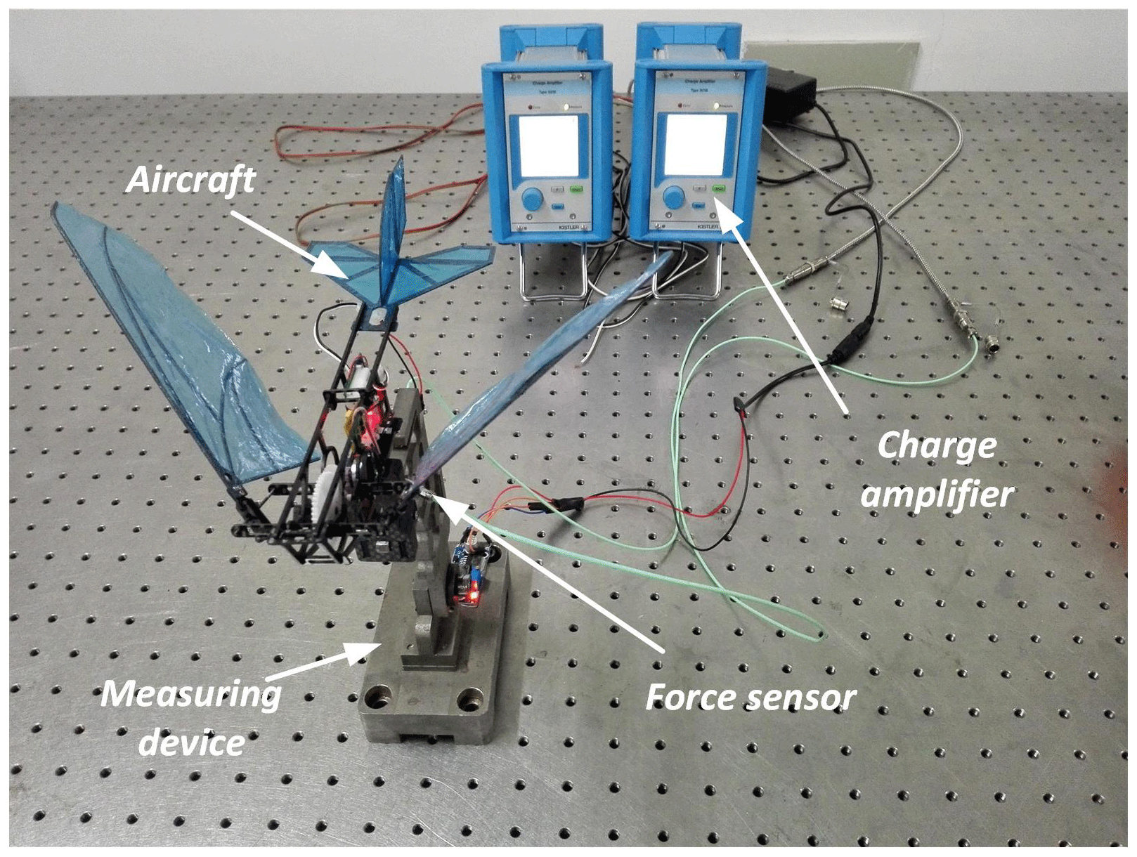
In order to investigate the effect of large flapping stroke angle and sweeping motion on aerodynamic performance, the aircraft was fixed on the force measurement device to measure horizontal and vertical forces directly, which can be viewed as total thrust and lift respectively. The force measurement device consists of two force sensors (Type 9211B, KISTLER) and a flexure hinge structure. A series of parametric tests were conducted for a range of free-stream velocities and flapping frequencies while keeping input voltage constant. Instead of lithium battery, DC voltage stabilizer was used to power the aircraft in case of instability induced by the consumption of battery electricity. Before the start of tests, two force sensors would be installed on particular positions of the force measurement device to measure horizontal and vertical forces respectively, as shown in Fig. 8. Then, different weights were used to calibrate the measurement system based on linear deformation theory. By measuring the pressure induced by the deformation of designed cantilever structure on the force measurement device, the data obtained from the sensors was sent to data acquisition module and data processing module. More details of the aircraft at different time can also be found in host computer. When the aircraft was excited, the force sensors were activated from idle condition to record the real-time value of the measured forces. At three different free-stream velocities, between 0 and 4 m s−1, the force data was gathered and filtered from about 60 continuous cycles with the frequency increasing from 0 to 11 Hz.
3.2 Force measurements
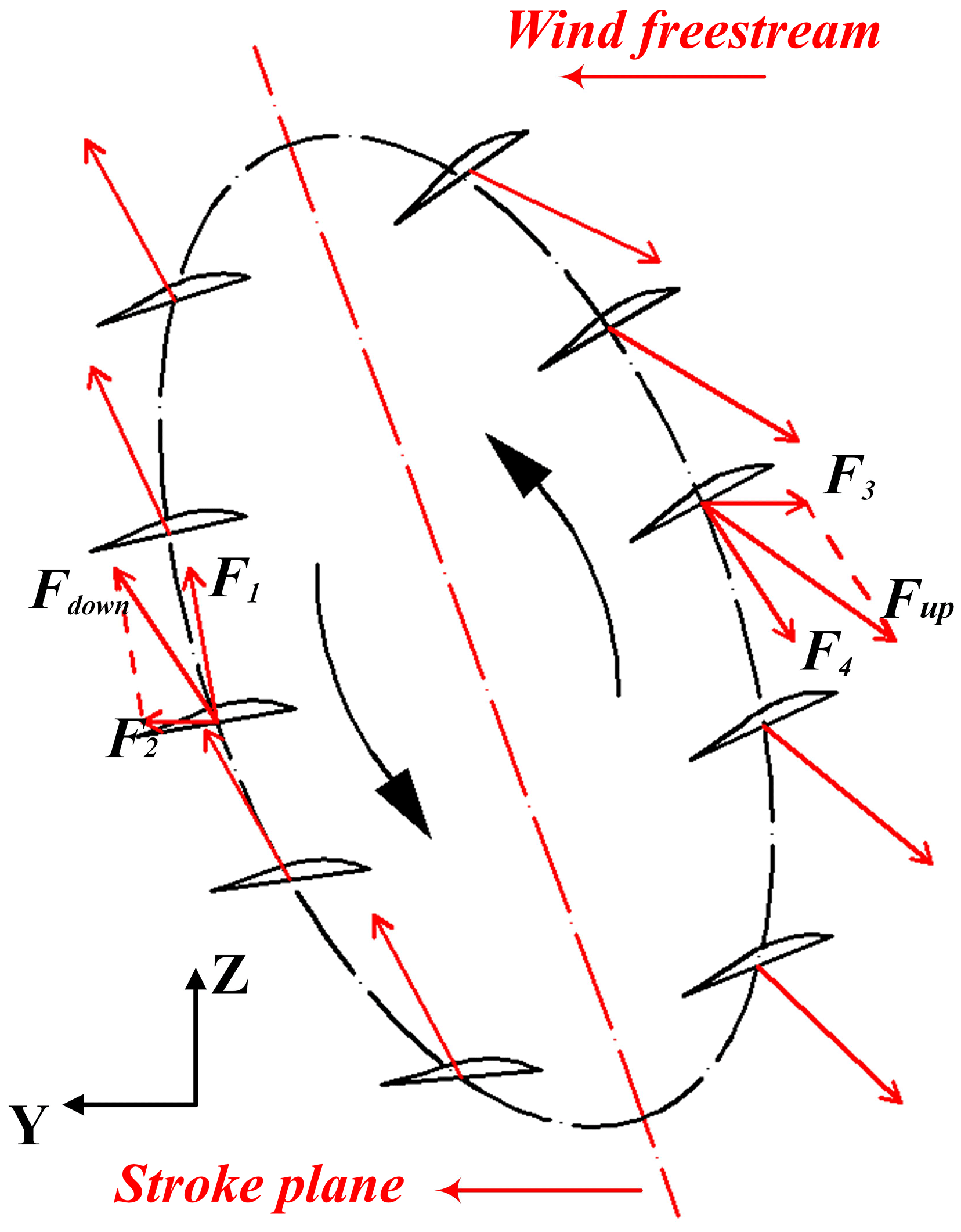
As seen in Fig. 9, the schematic diagram of aerodynamic forces are showed in a flapping cycle. During the downstroke and upstroke phase, the net force Fdown and Fup are determined by freestream velocity and wing downstroke relative velocity without considering the camber deformation in spanwise direction and wing rotation along Y′-axis direction. The direction and value of net forces change all the time due to the variation of wing movement direction and twisting along X-axis direction. The component of Fdown and Fup in Z-axis and Y-axis direction are taken as lift and thrust which are the measuring target data for the experiments.
The total lift consists of static lift and kinematic lift. The static lift is the force induced by wind speed without wing flapping motion and a complex function of the wing area, wing flexibility, attack angle, etc. The kinematic lift is caused by flapping kinematics and wing deformation, and greatly affected by the flapping frequency. The tests were repeated and real time data was obtained successfully. The average lift variations for different flapping frequencies and different wind speeds are plotted on Fig. 10. It shows that there are no obvious changes in average lift for low flapping frequencies (≤5 Hz) without considering wind speed, it may because that the flapping kinematics and wing deformation exert little influence on the aircraft under the condition of low flapping frequency. As the same time, the static lift plays the major role in this phase. When flapping frequency exceeds 5 Hz as shown in Fig. 9, the flapping kinematics and wing deformation become the major factors, resulting the total average lift rapid increase. On the condition of no wind, the maximum average lift could be up to 0.17 N with 10 Hz flapping frequency.

Due to the existence of 20∘ angle of attack, the direction of wing flapping is not perpendicular to horizontal plane. As a result, lift is the component force of the net force during flapping and the wings produce less lift compared to the mechanism without the attack angle. Figure 10 also shows that an increase of free-stream velocity results in lift increase, and for high frequency the increase will be less. As the tunnel wind speed increases, the static lift increases and kinematic lift has little changes leading the increase of total average lift. The varied proportion of static lift and kinematic lift induce by different frequencies and velocities determines the increase of the total lift. The maximum average lift could be up to 0.22 N under the condition of free-stream velocity.
As seen in Fig. 9, the upstroke phase generates all propelling force by acting on air, but there still a great loss for the negative effect of wind freestream, because of the opposite movement direction of freestream and wing in horizontal direction. Besides, the thrust generated in upstroke phase has to cancel out the drag in downstroke phase. As a result, the value of average thrust in Fig. 11 seems much smaller compared to lift in the same cycle. Figure 11 also shows the average thrust variations for different free-stream velocities and flapping frequencies. The tendency that an increase in flapping frequency always results in higher propulsive force is clear. Note that the average thrust value increases more quickly for higher flapping frequency compared to the lower. The reason is that increased relative velocity of flexible wing and wind freestream generates more propelling force to the wing in horizontal direction. It is easier to understand the relationship between flapping frequency and thrust with the supplement of Fig. 9.
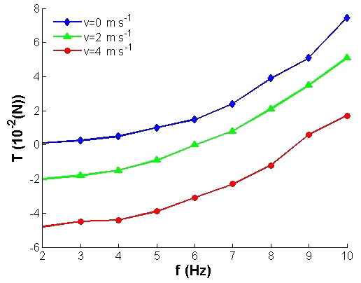
The general trend of average thrust for different windspeeds and frequencies are very similar. With the existence of attack angle, the forwardandback swing motion of wings increases the horizontal effective action area of airfoil under the effect of wind, which means more drag force generated under the action of the tunnel wind and more thrust in upstroke phase. When the flapping frequency is very low, the average drag value could be attained from the Fig. 11 directly. The drag increases with the growth of wind speed and reaches its maximum value when the wind speed is up to 4 m s−1. For higher flapping frequency, the propelling force is strengthened and it offsets part of drag force, thus the trend of total average thrust is gradually growing from negative value to the positive with the frequency increasing.
In this paper, a multi-DOF flapping wing air vehicle with elliptical wingtip trajectory was developed. It has the characteristic of 140∘ flapping stoke angle and forth-and-back swing motion. Multiple sliding and rotational joints are the designed key structure to achieve flapping and swing motion simultaneously. We also made tests on the aerodynamic performance of the aircraft. Lift and thrust were measured for different flapping frequencies and wind freestream velocity with the 20∘ attack angle. The increase of flapping frequency results in average lift increase and it is more obvious for larger flapping frequency. Different from the negative effect on thrust, the wind speed plays a positive role to lift increase. The value of average thrust is much smaller compared to lift in the same tests and the variation trend of average thrust seems similar to average lift. Finally, we believe that the mechanism is still too heavy to fly and the correlated flow visualization of the elliptical wingtip trajectory deserves follow-up attentions.
The research data in this paper includes structure parameters of FLMAV and the lift test data. The structure parameters of FLMAV are expressed in Table 1 and Fig. 7. The lift tests data is very simple and can be seen intuitively form Figs. 10 and 11 by reading the coordinate values of each point.
QLiu provided the idea of designing the FWMAV and directed QLi to fabricate the FWMAV. QLi designed, fabricated and assembled the FWMAV. XZ discussed the idea of designing the FWMAV with QLiu, and provided some advice in the FWMAV fabrication. PX helped QLi with the experiments. LR helped revise this paper. SP provided some advice in the experiments.
The authors declare that they have no conflict of interest.
This research has been supported by the China Postdoctoral Science Foundation (grant nos. 2014M551177 and 2015T80300), the Department of Science and Technology of Jilin Province (grant no. 20180101321JC) and by Fundamental Research Funds for the Central Universities.
This paper was edited by Jinguo Liu and reviewed by Ionut Geonea and one anonymous referee.
Au, L. T. K., Phan, H. V., and Park, H. C.: Optimal wing rotation angle by the unsteady blade element theory for maximum translational force generation in insect-mimicking flapping-wing micro air vehicle, J. Bionic Eng., 13, 261–270, 2016.
Bejgerowski, W., Ananthanarayanan, A., Mueller, D., and Gupta, S. K.: Integrated product and process design for a flapping wing drive mechanism, J. Mech. Design, 131, 061006–061014, 2009.
BionicFlyingFox: Ultra-lightweight flying object with intelligent kinematics, available at: https://www.festo.com/bionics, last access: April 2018.
Birch, J. M. and Dickinson, M. H.: Spanwise flow and the attachment of the leading-edge vortex on insect wings, Nature, 412, 729–733, 2001.
Dickinson, M. H., Lehmann, F. O., and Sane, S. P.: Wing rotation and the aerodynamic basis of insect flight, Science, 284, 1954–1960, 1999.
Ellington, C. P.: The aerodynamics of hovering insect flight. I. the quasi-steady analysis, Philos. T. R. Soc. Lond., 305, 17–40, 1984.
Ellington, C. P.: The novel aerodynamics of insect flight: applications to micro-air vehicles, J. Exp. Biol., 202, 3439–3448, 1999.
Ellington, C. P., Berg, C. V. D., Willmott, A. P., and Thomas, A. L. R.: Leading-edge vortices in insect flight, Nature, 384, 626–630, 1996.
Finio, B. M., Eum, B., Oland, C., and Wood, R. J.: Asymmetric flapping for a robotic fly using a hybrid power-control actuator, IEEE Int. C. Int. Robot., 2755–2762, 2009.
Hassanalian, M., Throneberry, G., and Abdelkefi, A.: Wing shape and dynamic twist design of bio-inspired nano air vehicles for forward flight purposes, Aerosp. Sci. Technol., 68, 518–529, 2017.
Keennon, M. and Grasmeyer, J.: Development of two MAVs and vision of the future of MAV design, AIAA International Air and Space Symposium and Exposition, The Next 100 Years, 14–17 July 2003, Dayton, Ohio, AIAA 2003-2901, https://doi.org/10.2514/6.2003-2901, 2003.
Lehmann, F. O.: The control of wing kinematics and flight forces in fruit flies (drosophila spp.), J. Exp. Biol., 201, 385–401, 1998.
Mcintosh, S. H., Agrawal, S. K., and Khan, Z.: Design of a mechanism for biaxial rotation of a wing for a hovering vehicle, IEEE-ASME T. Mech., 11, 145–153, 2006.
Meng, X. and Sun, M.: Wing kinematics, aerodynamic forces and vortex-wake structures in fruit-flies in forward flight, J. Bionic Eng., 13, 478–490, 2016.
Nguyen, Q. V., Park, H., Byun, D., and Goo, N.: Recent progress in developing a beetle-mimicking flapping-wing system, IEEE World Automation Congress, 19–23 September 2010, Kobe, Japan, 2154-4824, 2010.
Pornsin-Sirirak, T. N., Lee, S. W., Nassef, H., and Grasmeyer, J.: MEMS wing technology for a battery-powered ornithopter, IEEE The Thirteenth International Conference on MICRO Electro Mechanical Systems, 23–27 January 2000, Miyazaki, Japan, 799–804, 2000.
Pornsin-Sirirak, T. N., Tai, Y. C., Ho, C. M., and Keennon, M.: Microbat: a palm-sized electrically powered ornithopter, Proceedings of the Nasa/jpl Workshop on Biomorphic Robotics, available at: http://citeseerx.ist.psu.edu/viewdoc/summary?doi=10.1.1.540.116 (last access: 3 July 2019), 2001.
Pérez-Arancibia, N. O., Ma, K. Y., Galloway, K. C., Greenberg, J. D., and Wood, R. J.: First controlled vertical flight of a biologically inspired microrobot, Bioinspir. Biomim., 6, 036009, https://doi.org/10.1088/1748-3182/6/3/036009, 2011.
Rue, J., Chang, K., Ifju, P., Haftka, R., Schmitz, T., and Mcintire, J.: Fabrication and Analysis of Small Flapping Wings, Imaging Methods for Novel Materials and Challenging Applications, 3, 337–344, https://doi.org/10.1007/978-1-4614-4235-6_47, Springer, New York, 2013.
Ryan, M. and Su, H. J.: Classification of Flapping Wing Mechanisms for Micro Air Vehicles, ASME 2012 International Design Engineering Technical Conferences and Computers and Information in Engineering Conference, 105–115, ASME, Chicago, Illinois, USA, 2012.
Shyy, W., Aono, H., Chimakurthi, S. K., Trizila, P., Kang, C. K., and Cesnik, C. E. S.: Recent progress in flapping wing aerodynamics and aeroelasticity, Prog. Aerosp. Sci., 46, 284–327, 2010.
Weintraub, I., Sigthorsson, D., Oppenheimer, M. W., and Doman, D. B.: Kinematic Selection for a Tailless Flapping Wing Micro-Air Vehicle, AIAA Guidance, Navigation, and Control Conference, AIAA 2016-0892, San Diego, California, USA, 2015.
Weisfogh, T.: Quick estimates of flight fitness in hovering animals, including novel mechanisms for lift production, J. Exp. Biol., 59, 169–230, 1973.
Yang, L. J., Hsu, C. K., Hsiao, F. Y., Feng, C. K., and Shen, Y. K.: A Micro-Aerial-Vehicle (MAV) with figure-of-eight flapping induced by flexible wing frames, 47th AIAA Aerospace Sciences Meeting including the New Horizons Forum and Aerospace Exposition, AIAA 2099-875, Orlando, Florida, 2009.
Young, J., Walker, S. M., Bomphrey, R. J., Taylor, G. K., and Thomas, A. L. L.: Details of insect wing design and deformation enhance aerodynamic function and flight efficiency, Science, 325, 1549–1552, 2009.
Zbikowski, R.: On aerodynamic modelling of an insect-like flapping wing in hover for micro air vehicles, Philos. T. R. Soc. A, 360, 273–290, 2002.