the Creative Commons Attribution 4.0 License.
the Creative Commons Attribution 4.0 License.
 | 04 Jul 2019
Input Rationality Analysis of Three Degree of freedom Parallel Mechanism with Limbs of Embedding Structures
Gaowei Yang
Jianjun Zhang
Weimin Li
Kaicheng Qi
Three degrees of freedom (3-DoF) parallel mechanism (PM) with limbs of embedding structures is a kind of PM with a coupling relationship between limbs. In order to obtain a more desirable motion, the analysis of its actuated pairs shall be conducted. However, the fact that the existence of limbs coupling results in non-unique limb group, this mechanism has multiple limb groups. In this regard, the traditional input selection theory is not suitable for direct application in the input rationality analysis. Aiming to avoid this, a general extended input selection theory and limb group selection rule are proposed. The former tackles the traditional input selection theory which is not suitable for analyzing the input of PM with limbs of embedding structures since it does not take the influence of group into consideration, whereas the latter makes the calculation of the former easier. Based on the extended input selection theory and the limb group selection rule, the input and configuration of the 3-DoF PM with limbs of embedding structures are improved.


A lower-mobility parallel mechanism (PM) is one PM with DoFs fewer than 6-DoF, which has advantages of simpler mechanical architecture, lower cost of design and manufacturing. For these reasons, lower-mobility PMs are suitable for many tasks requiring fewer than 6-DoF (Wei and Li, 2018; Yi and Kim, 2018; Li and Huang, 2003a). In lower-mobility PMs, 3-DoF PMs have been extensively studied (Wu et al., 2017; Sameer and Tsai, 2002). Therefore, many novel 3-DoF PMs have been proposed, and these PMs fall into four categories: This first category is the 3-DoF translational PM including the delta PM and Tasi's PM (Liu et al., 2018); The second category is the 3-DoF rotational PM, such as spherical PM (Essomba et al., 2016; Houssem et al., 2017), 3-RPS parallel pyramid mechanism (Mu and Huang, 2007); The third is the 3-DoF PM has two rotational DoFs and one translational DoF (2R1T), for example, 3-CRC PM (Hussein and Ernesto, 2016), 2-RPU&SPR PM (Li et al., 2016) and 3-UPU PM (Wang et al., 2016). The forth category has two translational DoFs and one rotational DoF (2T1R).
This paper focuses on the forth category PM, i.e., PM with 2T1R. This category PM with rotational-translational output characteristic has high practical value in industrial production. In 1996, Gosselin proposed a 3-RRR PM with 2T1R, but its outputs are planar motions which limit its application (Gosselin et al., 1996). Thus, the spatial PM with 2T1R attracts considerable attention and it has become the current trend in research community. Zhang and his colleagues established the motion synthesis ideas based on the screw theory and synthesis for the type spatial PM and proposed many novel architectures (Zhang and Ting, 2013; Wu et al., 2009). Since many type synthesis methods based on certain complicated theory, such as GF set, displacement group theory of Lie Group Algebra, geometrical analysis, they are difficult to widely apply. Liu et al. introduced a concise and visual type synthesis method and proposed a PRU&PRC PM with high rotational capability, and this PM was used in 3T2R-DoF hybrid mechanism (Xie et al., 2014). All of the above work promote the development of mechanism and support the engineering applications, and these architectures have greatly enriched the diversity of lower-mobility PM.
However, the above PMs suffer from the shortcoming of smaller workspace, and their workspace are mostly hemispherical or semi-cylindrical. There is lack of the architectures with larger workspace, such as the architecture with full cylindrical workspace. Workspace is one of the most important criteria in designing a PM. A good design is one in which a PM of small mechanical size possesses a large workspace volume (DibakarSen and Singh, 2008; Fu and Gao, 2016). In order to satisfy this requirement, one 3-DoF PM with limbs of embedding structures is proposed (Zhang, 2008).
This PM has a coupled limb structure, which means a common axis for different limbs is presented. Compared with other PMs, where the common axis is located on the fixed platform (Brogardh and Kock, 2003; Brogardh, 2000; Isaksson et al., 2012; Lou and Li, 2013; Bin et al., 2018; Huang et al., 2010; Ni et al., 2015), this PM shares advantages such as compacted structures and no limb interference. Meanwhile, this PM enables complete cylindrical workspace and is more suitable for transportation in space. Therefore, this PM is highly promising for industrial applications.
Due to the key role of selection of actuated pairs in obtaining desired motions by this PM, actuated pairs of this PM were investigated. The input selection theory proposed by Huang Zhen is a powerful tool for this issue (Zhao and Huang, 2000; Zhao et al., 2017; Li et al., 2010; Huang et al., 2007; Li and Huang, 2003b). Based on the screw theory, the input selection theory evaluates rationality of the actuated pairs by limb groups (twist systems of different limbs). However, physical crossing or embedding of limbs of the 3-DoF PM with limbs of embedding structures leads to the presence of multiple limb groups, while only one of them is rational. If an irrational limb group was selected, the analysis may be incorrect, resulting in wrong conclusion on the rationality of inputs (details are shown in Sect. 3 of this article). The input selection theory, however, cannot identify the rational limb group. Hence, traditional input selection theory is not suitable for analysis of 3-DoF PM with limbs of embedding structures as it doesn't consider the effects of multiple limb groups. Instead, it shall be extended.
This paper proposes extended input selection theory which is used to determine reasonable inputs and limb group, in the meantime, limb group selection rule is summarized. In order to verify their generality, the inputs of one 2-DoF PM with limbs of embedding structures (Qu et al., 2009) is analyzed in Sect. 4. The structure of this paper is organized as follows: Sect. 2 presents a detailed description about the two PMs, and analyses mobility. Section 3 proposes extended input selection theory. Section 4 determines the reasonable inputs and limb group of 3-DoF and 2-DoF PM with limbs of embedding structures. Section 5 concludes the paper.
2.1 Architecture description
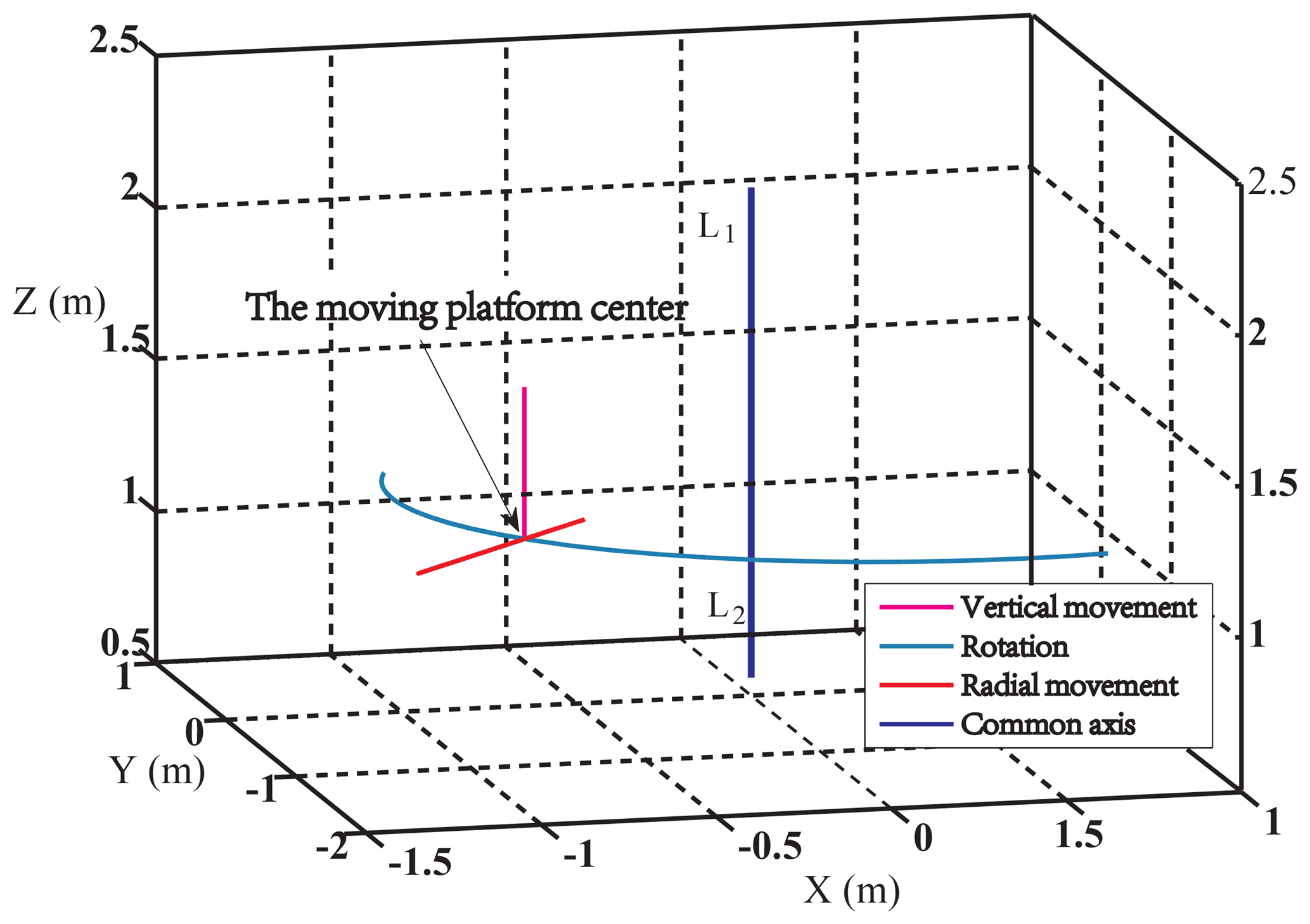
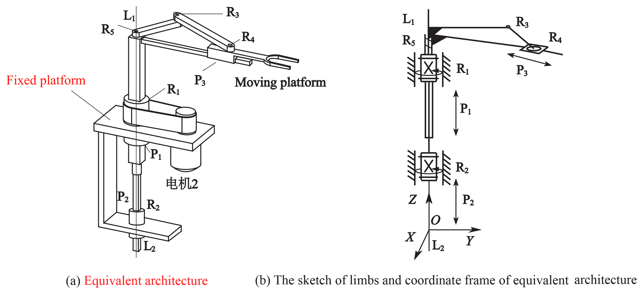
The CAD model and prototypes of 3-DoF PM with limbs of embedding structures are seen in Fig. 1a–c. The moving platform is connected with guideway and bar 2 by kinematic pair R4 and P3, respectively; the bar 2 is connected with bar 1 by R3, and the guideway is fixed with connection shaft 1; the connecting shaft 2, being fixed to the bar 1, is connected to the connecting shaft 1 and the fixed platform through R5 and P2. Support plate is connected with ball screw and fixed platform by screw pair H1 and revolute pair R6, respectively. All the kinematic pairs mentioned above have the same axes except the prismatic pair P3, which is indicated by L1L2. This PM has three motors, where the motor 1 drives moving platform to move along L1L2 axis by ball screw and connection shaft 1; the motor 2 drives the moving platform to rotate round L1L2 axis by belt and the connecting shaft 1; the motor drives moving platform to move along guideway, namely, radial movement centered on L1L2 axis. The workspace of this PM is complete cylindrical surface, and the motion trajectory is seen in Fig. 2.
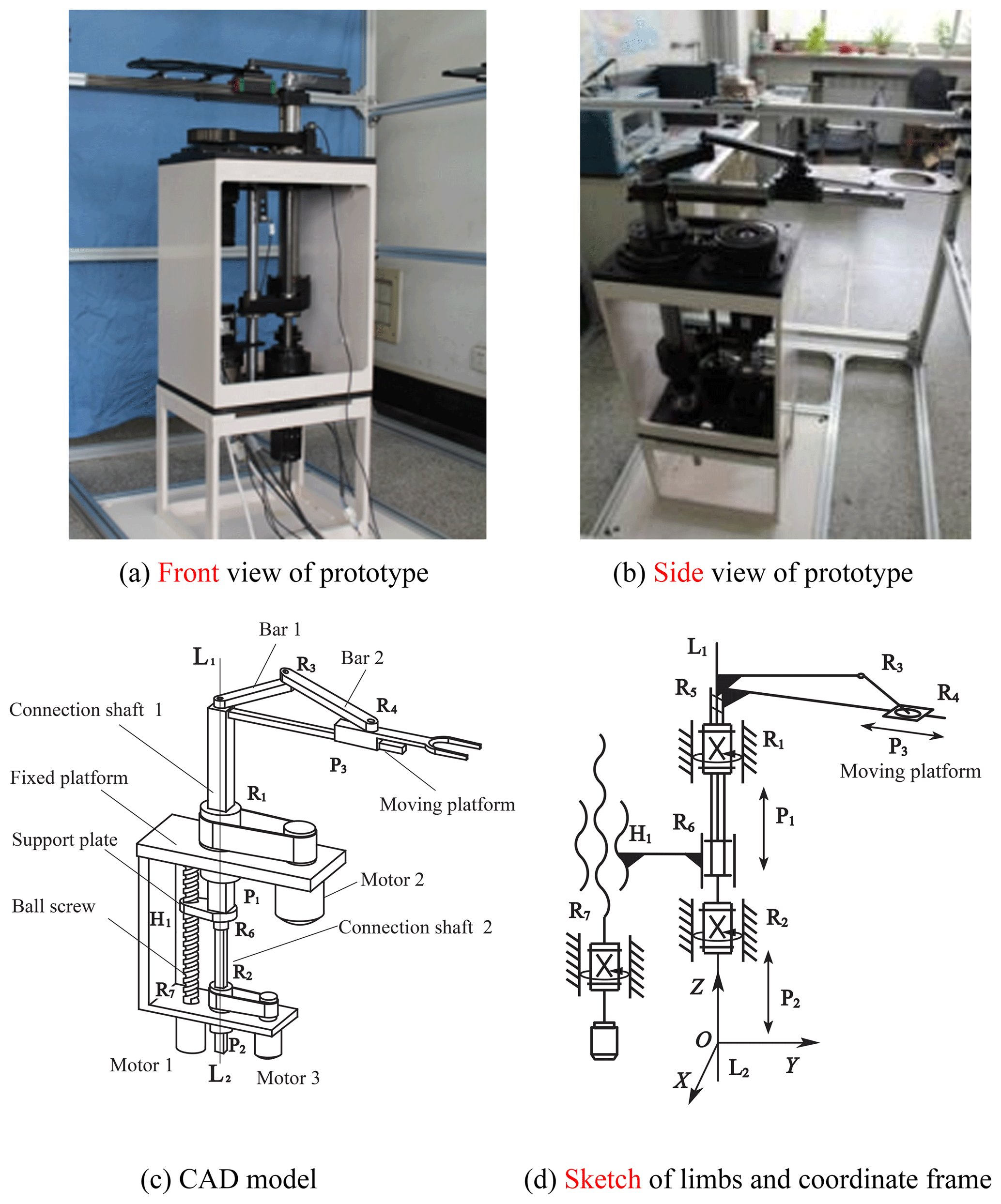
This coordinate of this PM is seen in Fig. 1d, where the origin is coincided with the middle point of revolute pair R2; the Z axis is the axis of prismatic P1, P2, and is coincided with L1L2; the kinematic pair H1, R7 are both on the YZ plane, and is parallel to the Z axis.
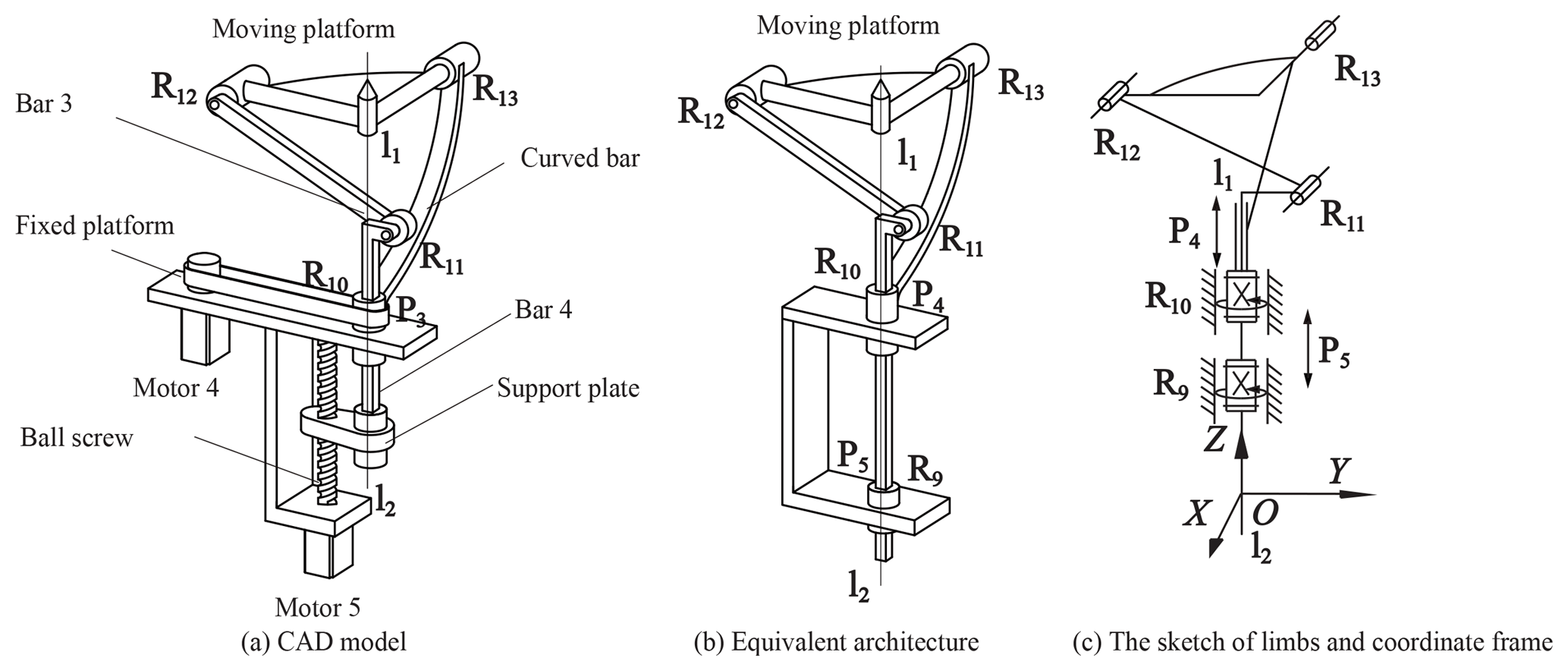
The CAD mode and equivalent architecture of 2-DoF decoupled PM with limbs of embedding structures are seen in Fig. 3a–c. The moving platform is connected by bar 3 and curved bar by revolute pair R12 and R13, respectively. Bar 3 and curved bar are connected with bar 4 and fixed platform by revolute pair R11 and R10, respectively. One end of bar 4 is connected with curved bar by prismatic P4, and the other end is connected with support plate by revolute pair R9. The ball screw is connected with support plate and fixed platform by screw pair H2 and revolute pair R8. The kinematic pairs H2, R8, R9, R10 and P4 have the same axis l1l2. This PM has two motors, where the motor 4 drives the moving platform to rotate around axis l1l2; the motor 5 drives he moving platform to rotate with radial axis of l1l2.
In this PM, the component (ball screw and support plate) between R8 and R9 can be deemed to prismatic inputs. According to this characteristic, equivalent mechanism is obtained as Fig. 3b. The coordinate of equivalent mechanism is seen as Fig. 3c, where the P4 and R10 are inputs; the origin is coincided with the middle point of revolute pair R10; Z axis is coincided with l1l2. Limbs and moving platform form closed chain structure.
2.2 3-DoF and 2-DoF PM with limbs of embedding structures architecture analysis
Both of the previous PMs have coupled limbs, which embed each other, and the kinematics pairs included in the intersection of limbs have common axis L1L2 and l1l2. Limbs, moving platform and fixed platform in one PMs forms closed-loop structure by common axis. This coupled structure makes PM more compact, in the meanwhile avoids limbs interference and obtains larger workspace. However, this configuration also leads to uncertainties of the components or kinematic pairs included in limbs, such as in 3-DoF PM with limbs of embedding structures, the limbs from revolute pair R7 to moving platform is either R7H1R6P1P3 limb or R7H1R6P1R5R3R4 limb. This problem will be discussed in Sect. 3.
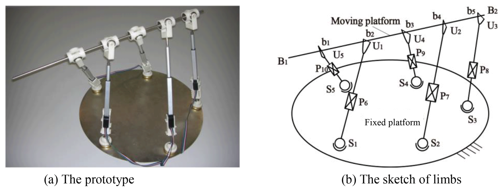
Besides PM with limbs of embedding structures, the extant PM (Borràs et al., 2014, 2011, 2009; Borràs and Thomas, 2008) also has common axis (common actuated axis), such as 5-DoF pentaponds (seen in Fig. 4).
This PM has five identical limbs, each of which has one spherical pair (Si, i=1, …, 5), one prismatic pair (Pi, i=6, …, 10) and universal pair (Ui, i=1, …, 5). The moving platform can be deemed to one line, and this line is indicated as B1B2. B1B2 is coincided with one axis of Ui, and intersection at point bi (i=1, …, 5) of the other axis. Therefore, B1B2 is the common axis (common actuated axis). Despite both 5-DoF pentaponds PM and PM with limbs of embedding structure have common axis, two mechanisms are disparate. The main distinction is as follows:
-
The limbs in 5-DoF pentaponds PM are independent of each other, and the limbs in PM with limbs of embedding structure exist coupling. Compared to the latter, 5-DoF pentaponds PM is more likely to have limb interference.
-
The axis B1B2 is located on the moving platform. However, with regards to 3-DoF PM with limbs of embedding structures, the moving platform is separated from the common axis (common actuated axis), thus increasing the structure's working space.
The input selection theory proposed by Huang Zhen is a powerful tool for analysis of rationality of inputs of PM. According to this theory, the rational actuated pairs of PM must lead to no remnant freedom singularity of this PM. In case of remnant freedom singularity, PM inputs are irrational and a new set of actuated pairs shall be selected. Actually, the remnant freedom singularity of PM is affected by the selection of the twist system of limbs and the actuated pairs. For PMs with determined twist system of limbs (PMs with one limb group only), irrational input selection is the only possible cause of remnant freedom singularity of PM. Hence, the input selection theory can be directly applied.
Nevertheless, for PM with limbs of embedding structures, the twist system of limbs is not determined and multiple limb groups are present. In this case, besides irrational input selection, irrational limb group can also lead to remnant freedom singularity of PM, if not errors in DoF calculations. Therefore, the input selection theory shall not be applied for judgment of 3-DoF PM with limbs of embedding structures without extension. The procedure of extended input selection theory can be stated as follows: (1) Select a limb group; (2) Calculate DoF based on twist systems of limb contained by this limb group; (3) If DoF calculation is correction, proceed to Step 4. Otherwise, return to Step 1; (4) Upon determination of correct calculation of PM, the remnant freedom of PM is analyzed: (a) Lock the actuated pairs, namely delete the actuated screws corresponding to the actuated pairs from twist systems of different limbs; (b) Calculate the limb reciprocal screw systems with inputs being locked of different limbs; (c) The mechanism constraint screw system after locking the inputs is gained from the limb reciprocal screw systems after locking inputs. To prevent input interference or invalid input in the same limb, the number of increased reciprocal in one limb after locking inputs must be equal to the number of locking inputs of this limb. (d) Calculate the rank (r) of the constraint screw system with inputs being locked of the mechanism. If r=6, no remnant freedom is presented; if r<6, remnant freedom and irrational input selection are present, a new limb group shall be selected and all steps above shall be repeated.
According to the extended input selection theory, for any actuated pair, if the DoF obtained by twists of different limbs of the limb group is correct, r=6, and the quantity of additional reciprocal systems on limbs with inputs being locked equals to that of actuated pairs, it can be concluded that the actuated pairs are rational. If any of these requirements is not met, it can be concluded that the input selection is irrational and a new set of actuated pairs shall be selected. Additionally, kinematic pairs near the fixed platform shall be preferred as the actuated pairs.
The extended input selection theory is suitable for 3-DoF PM with limbs of embedding structures and 2-DoF PM in the same category. Additionally, upon determination of rationality of the input kinematic pair, the rational limb group of PM with limb of embedding structures is determined, thus providing references for further studies of PM, including kinematic singularity analysis, instantaneous motion, and calculations of first-order influence coefficient.
4.1 Input rationality analysis of 3-DoF PM with limbs of embedding structures
4.1.1 The rationality analysis of the initial actuated pairs
This coordinate of 3-DoF PM with limbs of embedding structures is seen in Fig. 1d, this PM has five limb groups (The actuated pairs are R1, R7 and R2):
-
limb groups. 1: R7H1R6P1R1R5R3R4 limb, P1R1R5R3R4 limb, R2P2R5P3 limb;
-
limb groups. 2: R7H1R6P1P3 limb, P1R1P3 limb, R2P2R3R4 limb;
-
limb groups. 3: R7H1R6P1R1R5R3R4 limb, R2P2R5P3 limb;
-
limb groups. 4: R7H1R6P1R1P3 limb, R2P2R3R4 limb;
-
limb groups. 5: R7H1R6P1R5R3R4 limb, R1R5R3R4 limb, R2P2R5P3 limb.
In limb group 1, the first limb is R7H1R6P1R5R3R4 limb, the second limb is P1R1R5R3R4 limb, the third limb is R2P2R5P3 limb. The limb twist systems of the three limbs are as follows (the actuated screws are , and ):
Where, is the twist associated with the jth kinematic pair in the ith limb of limb group M; and are in YZ plane, the axes of the two twists are parallel to Z axis; the vector , , and , and is the coordinate of the center of moving platform. The reciprocal screw systems of each limb in limb group 1 are as follows:
Where, a and b are determined by: . By Eqs. (4)–(6), the mechanism constraint screw system can be obtained as follows:
By Eq. (7), the mechanism twist system $1:
Equation (8) demonstrates this PM has three DoF as follows: (a) Moving platform rotates around Z axis, and indicated by $11; (b) Moving platform translation along guideway, namely, radial translation centered on Z axis, and indicated by $12; (c) Moving platform rotation along Z axis, and indicated by $13.
It can be seemed from (a)–(c), this PM do not have parasitic motion, and the DoF is correct. The remnant-freedom analyzes as follows:
Delete the actuated screws in Eqs. (1)–(3), the limb twist systems of each limb after locking the inputs are as follows:
According to Eqs. (9)–(11), the three limb reciprocal screw systems after locking the inputs are as follows:
Based on Eqs. (12)–(14), the reciprocal screws in the three limbs after locking the inputs have not increased, so the inputs in limb group 1 are irrational. The mechanism constraint screw system after locking the inputs, namely, is:
Equation (15) validates that, the rank of is less than six, so the PM has remnant-freedom at this time. Based on the same method, the limb groups 2–5 does not meet input rationality judgment condition, and the actuated pairs R1, R7 and R2 are irrational.
It is worth noting that, in the analysis of limb group 2–4, this PM has remnant-freedom, but this PM appears miscalculation DoF when the limb 5 is selected. The process of analysis is as follows:
In limb group 5, the first limb is R7H1R6P1R5R3R4 limb, the second limb is R2P2R5P3 limb, the third limb is R1R5R3R4 limb. The first and second limb twist systems are the same as Eqs. (1) and (3), the third limb twist system is as follows:
The mechanism constraint screw system, namely, :
The DoF obtained from limb group 5 is:
Obviously, the number of DoF is wrong. Contrast to limb group 1, the case of this problem is that lack of prismatic pair P1 in R1R5R3R4 limb changes the mechanism constraint screw system. Prismatic pair P1 indicates translation along Z axis, which is synchronous motion of each component, so the twist indicates this motion must be included in each limb twist system, or one twist has same axis. Therefore, one conclusion is obtained: in order to ensure correct DoF, the twist indicates this motion must be included in each limb twist system (conclusion 1 for short). Conclusion 1 is a necessary condition to ensure correct DoF, and this conclusion can delete irrational limb group to simplify the analysis process.
4.1.2 Reasonable justification after reselected actuated pairs
When the actuated pairs are R7, R1 and R2, all the limb groups do not satisfy the judging conditions, so the actuated pairs need to be reselected. According to the principle that the kinematic pairs near the fixed platform are selected as the actuated pairs, the mechanism has two sets of kinematic pairs for actuated pairs, the first group is R1, P1, R2, and the second group is R1, P2, R2. In order to facilitate the transformation, the second sets of kinematic pairs are selected, and the motor 1 is changed to a linear motor at this time. After reselected inputs, the PM is seen in Fig. 5a, the sketch of limbs and actuated pairs coordinate frame of equivalent architecture are seen in Fig. 5b.
When actuated pairs are R1, R7 and R2, the limb groups are as follows: (a) Limb group I: P1R1P3 limb, P2R2R3R4 limb; (b) Limb group II: P2R5P1R1P3 limb, R2R3R4 limb; (c) Limb group III: P1R1R5R3R4 limb, R2P2 R5P1P3 limb.
The conclusion 1 mentioned above shows that the limb group II will lead to the error of the calculation of the DoF. For the irrational limb group, the rationality of the inputs is analyzed only through the remaining limb groups. The analysis process is as follows:
In limb group I, the first limb is P1R1P3 limb and the second limb is P2R2R3R4 limb, the twist system of the first limb is:
The twist system of the second limb in limb group I:
Based on Eqs. (19)–(20), the reciprocal screw systems of each limb are as follows:
Based on Eqs. (21)–(22), the mechanism twist system $I is:
According to Eq. (23), the DoF is correct. The two limb reciprocal screw systems after locking the inputs are as follows:
In which, a1, b1 and b1 are determined by the equation group . The quantity of additional reciprocal screw is equal to the number of actuated pairs, indicating that the inputs of each limb are reasonable. The mechanism constraint screw system after locking inputs, namely, is as follows:
The rank of Eq. (26) is six, namely, this PM loses all DoFs at this time. However, Eq. (25) only demonstrates one configuration, it is needed to analyze whether there is remnant-freedom in other configurations.
Let r1, r2 and r3 indicates vectors of guideway, bar 2 and bar 1, respectively. It can be obtained from Eqs. (27)–(29):
In order to avoid singularity, just meet the condition: |r3|<|r2|. In fact, this PM meets this condition, so dead point dose not present, namely, this PM dose not present remnant-freedom in any configuration, so the inputs are reasonable. Using the same method, the is as follows:
The rank of Eq. (34) is less than six, so the PM has remnant-freedom at this time. Contrast to limb group I and II, the case of this problem is excess kinematic pairs in limb group III, which leads to insufficient constraint of moving platform. Therefore, the other conclusion is obtained: in the process of input analysis, the limb group with fewer kinematic pairs should be preferred. Conclusion 1 and 2 can be called limb group selection rule.
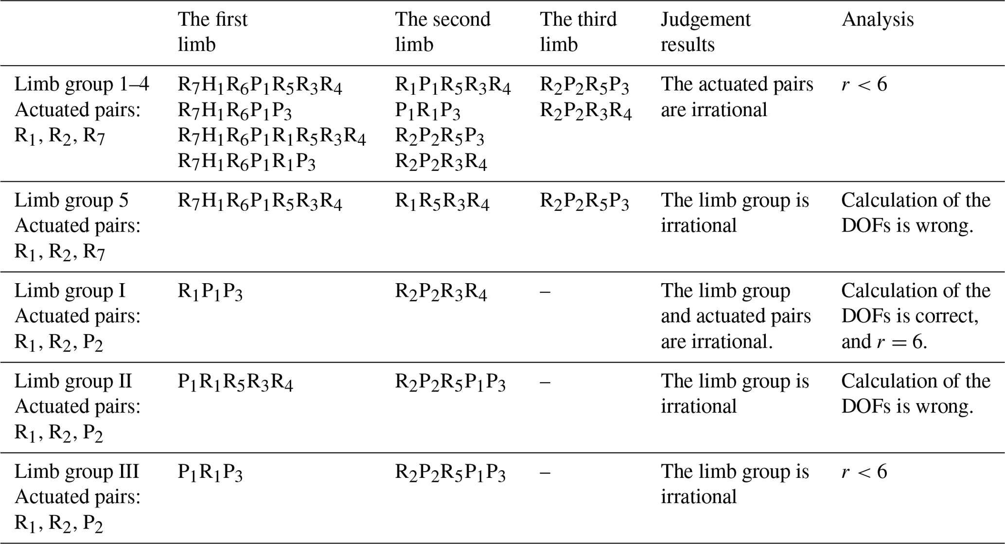
According to analyze different inputs and limb groups (comparative analysis seen in Table 1), the reasonable inputs and limb group of 3-DoF PM with limbs of embedding structures are determined, and limb group selection rule is summarized. This research lays on a foundation for input rationality analysis for similar PM.
4.2 Reasonable justification of inputs of 2-DoF PM with limbs of embedding structures
The coordinate system of 2-DoF PM with limbs of embedding structures is shown in Fig. 6, in which P5, R10 are the actuated pairs. There are two limb groups:
-
Limb group A: P5R9R11R12 limb (Fig. 6a), R10R13 limb (Fig. 6b).
-
Limb group B: P5R9P4R10R13 limb, R10P4R11R12 limb.
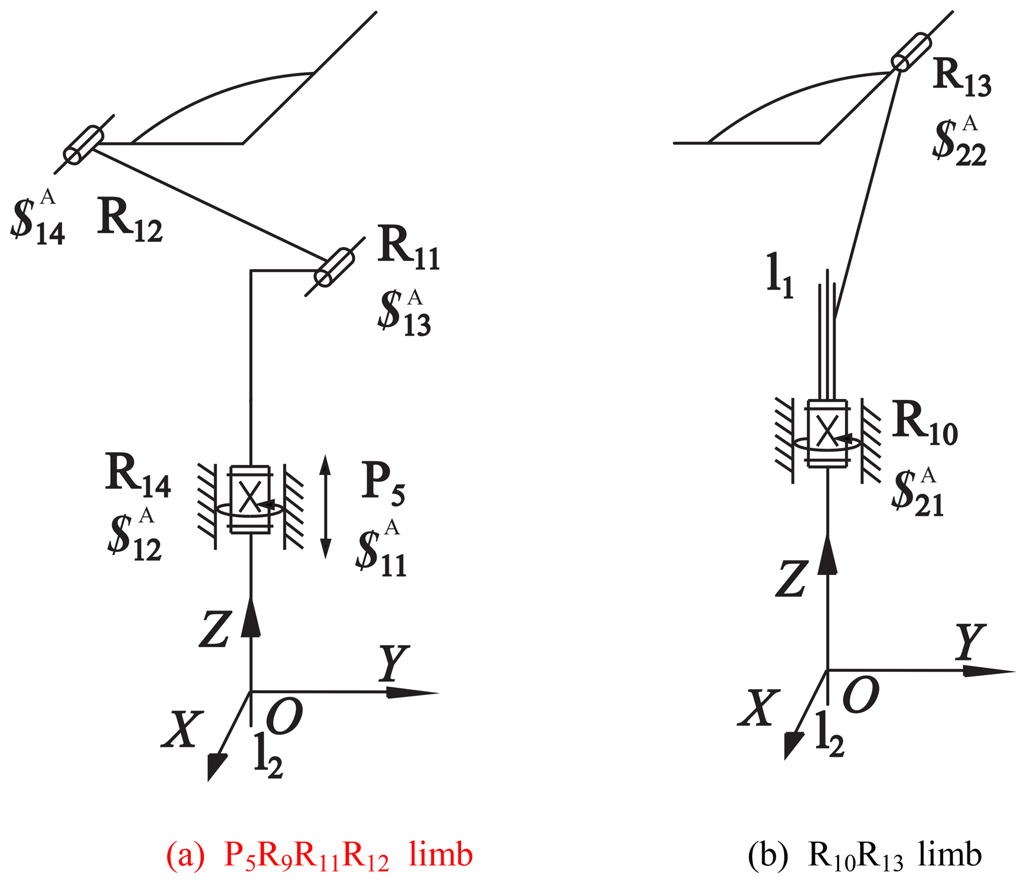
According to limb group selection rule, limb group A is selected to analyze input rationality. Let the first limb is P5R14R11R12 limb, the second limb is R10R13 limb. The limb twists systems are as follows:
The reciprocal screw systems of each limb are as follows:
By Eqs. (37)–(38), the twist system of the mechanism is as follows:
Where, (a) demonstrates a revolution DoF around Z axis; (b) demonstrates a revolution DoF around arbitrary axis in XY plane. According to Eq. (39), the workspace of this PM is sphere. The limb reciprocal screw systems after locking the inputs are as follows:
Based on Eqs. (40)–(41), the quantity of additional reciprocal screw is equal to the number of actuated screws, so the inputs in each limb are reasonable.
The rank of Eq. (42) is six, which indicates that the platform loses all DoFs, and the inputs of the mechanism are reasonable. At the same time, the limb group A can be determined as a reasonable limb group. For the limb group B, the constrained screw system of the moving platform only consists of three reciprocal screws, that is, the constraint of the moving platform is insufficient. According to the constraint screw system of the mechanism, the twist system of the mechanism is as follows:
According to Eq. (36), the DoF of the mechanism is wrong, so the limb group B is irrational. Based on the analysis of this PM, the extended input selection theory and the limb group selection rule are verified to have generality.
According to analyze the characteristic of 3-DoF PM with limbs of embedding structures and the influence factor of remnant-freedom, the extended input selection theory is proposed. Through extended input selection theory, the reasonable inputs and limb group of 3-DoF PM with limbs of embedding structures is determined, and limb group selection rule is summarized. Based on the analysis of the inputs of 2-DoF PM with limbs of embedding structures, the extended input selection theory and limb group selection rule verified to have generality.
All data in this paper is obtained by calculated. The calculation is based on screw theory. Screw theory comes from Huang et al. (2006).
GY prepared the manuscript with the help of JZ, WL and KQ.
The authors declare that they have no conflict of interest.
The authors gratefully acknowledge the contribution of Liu Teng and Wu Jinhui for fruitful discussions about this work.
This research has been supported by the National Natural Science Foundation of China (grant no. 51175144).
This paper was edited by Guimin Chen and reviewed by two anonymous referees.
Bin, L., Lou, Y. J., and Li, Z. B.: Acceleration analysis and optimal design of a 3-DoF co-axis parallel manipulator for pick-and-place applications, Adv. Mech. Eng., 10, 1–15, 2018.
Borràs, J. and Thomas, F.: Architecture singularities in flagged parallel manipulators, International Conference on Robotics and Automation, 384–385, IEEE, Pasadena, CA, USA, 2008.
Borràs, J., Thomas, F., and Ottaviano, M.: A reconfigurable 5-DoF 5-SPU parallel platform, International Conference on Reconfigurable Mechanism & Robots, 617–623, IEEE, London, UK, 2009.
Borràs, J., Thomas, F., and Torras, C.: Architectural singularities of a class of pentapods, Mech. Mach. Theory, 46, 1107–1120, 2011.
Borràs, J., Thomas, F., and Torras, C.: New geometric approaches to the analysis and design of Stewart–Gough platforms, IEEE/ASME Transactions on Mechatronics, 19, 445–455, 2014.
Brogardh, T.: Design of high performance parallel arm for industrial application, in: Proceedings of a Symposium Commemorating the Legacy, Works, and Life of Sir Robert Ball, 9–11, University of Cambridge, 2000.
Brogardh, T. and Kock, S.: An industrial robot and a method for manipulation in an industrial robot comprising a parallel kinematic manipulator, European Patent: EP1513657B1, European intellectual property office, Paris, 2003.
DibakarSen, B. and Singh, N.: A geometric approach for determining inner and exterior boundaries of workspaces of planar manipulators, J. Mech. Design, 130, 1–9, 2008.
Essomba, T., Laribi, M. A., and Zeghloul, S.: Optimal synthesis of a spherical parallel mechanism for medical application, Robotica, 34, 671–686, 2016.
Fu, J. X. and Gao, F.: Designing a Novel Three-degree-of-freedom Parallel Robot Based on Workspace, Int. J. Adv. Robot. Syst., 13, 1–15, 2016.
Gosselin, C., Lemieux, S., and Merlet, J. P.: A new architecture of planar three-degree-of-freedom parallel manipulator, Proceedings of the 1996 IEEE International Conference on Robotics and Automation, 3738–3743, IEEE, Minneapolis, Minnesota, 1996.
Houssem, S., Laribi, M. A., and Zeghloul, S.: Optimal torque distribution for a redundant 3-RRR spherical parallel manipulator used as a haptic medical device, Robot. Auton. Syst., 89, 40–50, 2017.
Huang, T., Wang, M., and Ni, Y., Mei, J., Song, Y., Zhao, X., Wang, H., Shen, Z., and Wang, D.: A high-speed pick-and-place parallel robotic mechanism capable of full rotation, China Patent: 201010290635.1, Intellectual Property Office of the People's Republic of China, Tianjin, China, 2010.
Huang, Z., Zhao, Y. S., and Zhao, T. S.: Advanced Spatial Mechanism, Higher Education Press, Beijing, 2006.
Huang, Z., Mu, D., and Zeng, D.: The screw motion simulation on 3-RPS parallel pyramid mechanism, International Conference on Mechatronics and Automation, 2860–2864, IEEE, Harbin, China, 2007.
Hussein, T. and Ernesto, R.: Instantaneous kinematics analysis via screw-theory of a novel 3-CRC parallel mechanism, Int. J. Adv. Robot. Syst., 13, 1–16, 2016.
Isaksson, M., Brogardh, T., and Nahavandi, S.: Parallel manipulators with a rotation-symmetric arm system, J. Mech. Design, 134, 114–503, 2012.
Li, B., Li, Y. M., and Zhao, X. H.: Kinematics analysis of a novel over-constrained three degree-of-freedom spatial parallel manipulator, Mech. Mach. Theory, 104, 222–223, 2016.
Li, E. W., Zhao, T. S., Wang, C., Zhao, Y. Z., Bian, H., and Chen, Y. H.: Type synthesis and analysis of two-axis swaying platform with virtual rotation axis, International Conference on Reconfigurable Mechanisms and Robots, Vol. 36, 445–469, IEEE, Beijing, China, 2010.
Li, Q. C. and Huang, Z.: Mobility analysis of lower-mobility parallel manipulators based on screw theory, IEEE International Conference on Robotics and Automation, 2003, Proceedings ICRA. IEEE, 1, 1179–1184, 2003a.
Li, Q. C. and Huang, Z.: Symmetrical lower-mobility parallel mechanisms using the constraint-synthesis method, Int. J. Robot. Res., 22, 59–79, 2003b.
Liu, G. Y., Chen, Y. N., and Xie, Z., and Geng, X.: GA/SQP optimization for the dimensional synthesis of a delta mechanism based haptic device design, Robot. CIM-Int. Manuf., 51, 73–84, 2018.
Lou, Y. and Li, Z.: Kinematics and optimal design of a novel 3-DoF parallel manipulator for pick-and-place applications, International Journal of Mechatronics and Automation, 3, 181–190, 2013.
Mu, D. J. and Huang, Z.: The movement simulation of 3-RPS parallel pyramid mechanism, ASME 2007 International Mechanical Engineering Congress and Exposition, 691–698, ASME, Washington, USA, 2007.
Ni, Y. B., Wu, N., and Zhong, X.: Dimensional synthesis of a 3-DOF parallel manipulator with full cir cle rotation, Chin. J. Mech. Eng., 28, 168–174, 2015.
Qu, Y. X., Xu, A. P., and Li, W, M.: Velocity performance analysis of a novel 2-DoF fully-decoupled spherical parallel mechanism, Second International Conference on Intelligent Networks and Intelligent Systems, IEEE Computer Society, 546–549, IEEE, Tianjin, China, 2009.
Sameer, A. J. and Tsai, L. W.: Jacobian ansysis of limited-DoF parallel manipulators, T. ASME, 124, 254–258, 2002.
Wang, L. P., Xu, H. Y., and Guan, L. W.: A novel 3-PUU parallel mechanism and its kinematic issues, Robot. CIM-Int. Manuf., 42, 86–102, 2016.
Wei, Y. L. and Li, Q. C.: A New Family of Symmetrical 2T2R Parallel Mechanisms Without Parasitic Motion, J. Mech. Robot., 10, 1–10, 2018.
Wu, J., Yan, R. J., and Shin, K. S., Han, C., and Chen, I.: A 3-DOF quick-action parallel manipulator based on four linkage mechanisms with high-speed cam, Mech. Mach. Theory, 115, 168–196, 2017.
Wu, X., Chen, M. L., and Zhang, Y. B.: Kinematic analysis and simulation of a new parallel mechanism two translational and one rotational output, Proceedings of the 2009 IEEE International Conference on Robotics and Automation, 1568–1573, IEEE, Zhuhai/Macau, China, 2009.
Xie, F. G., Liu, X. J., You, Z., and Wang, J. S.: Type synthesis of 2T1R-type parallel kinematic mechanisms and the application in manufacturing, Robot. CIM-Int. Manuf., 30, 1–10, 2014.
Yi, B. J. and Kim, W. K.: Task-oriented type synthesis of the lower-mobility parallel mechanisms with a common platform, J. Mech. Sci. Technol., 32, 5573–5387, 2018.
Zhang, J. J.: PARALLEL ROBOTICS: Recent advances in research and application, in: A family of parallel manipulators with mobile platform rotating continuously: manipulators with limbs of embedding structures, edited by: Wang, J. S. and Liu, X. J., New York, Nova Science Publisher, 88–93, 2008.
Zhang, Y. B. and Ting, K. I.: Design and analysis of a spatial 3-DOF parallel manipulator with 2T1R-Type, Int. J. Adv. Robot. Syst., 10, 226–134, 2013.
Zhao, T. S. and Huang, Z.: Theory and application of selecting actuating components of spatial parallel mechanisms, Chin. J. Mech. Eng., 36, 81–85, 2000.
Zhao, T. S., Li, E. W., and Bian, H.: Type synthesis and analysis of rotational parallel mechanisms with a virtual continuous axis, Mech. Mach. Theory, 109, 139–154, 2017.
- Abstract
- Introduction
- Architecture and mobility analysis of 3-DoF and 2-DoF PM with limbs of embedding structures
- Extended input selection theory
- Input rationality analysis of 3-DoF and 2-DoF PMs with limbs of embedding structures
- Conclusion
- Data availability
- Author contributions
- Competing interests
- Acknowledgements
- Financial support
- Review statement
- References