the Creative Commons Attribution 4.0 License.
the Creative Commons Attribution 4.0 License.
 | 27 Jun 2019
Influence of eccentricity of double eccentricity sleeves on the movements of swing head in rotary forging press
Xin Liu
Chun Dong Zhu
Xi Jiang
Yi Zhang
Rotary forging is an innovative incremental metal forming process, In a rotary forging press with double eccentricity sleeves, the eccentricity of double eccentricity sleeves has significant effects on the movements of swing head. The internal and external eccentricity of the existing rotary forging machine is equal, except circular path, the rotation speed of internal and external eccentric sleeves for the rose curve, spirals curve and straight line is not equal, which will produce the oscillation centrifugal force during the forming process and cause the violent shaking on the machine. The shaking of the machine has an important influence on the life of the equipment parts machining accuracy and surface profile of parts, reducing the production efficiency. This paper proposes a method to reduce shaking by changing eccentricity and studied the influence of unequal eccentricity on the movements of swing head obtained the design relationship of internal and external sleeves eccentricity, which can reduce the shaking in rotary forging press. This study improving the working state of the rotary forging machine and economic benefits.


Rotary forging is a continuous local pressure plastic forming technology (Zhang, 1984; Zhu et al., 2011, 2015). Because the contact area between the upper die and billet is partial during the rotary forging process (Nam et al., 2014; Wang et al., 2005; Wang and Zhou, 1999), the load force in rotary forging is only about 10 %–20 % of that in conventional forging. Besides saving energy, it has many other advantages such as high precision, saving materials, low noise, therefore it has been widely used in mechanical, electrical, aerospace, petroleum, chemical industry, etc.
Due to its advantages above, many scholars have conducted researches, mainly on the calculation of energetic parameters (Oudin et al., 1985; Choi et al., 1997; Canta et al., 1998), contact mechanisms (Hawkyard et al., 1977; Pei et al., 1982; Han and Hua, 2011, 2012) and the deformation mechanisms of billets (Nowak et al., 2008; Montoya et al., 2008; Deng et al., 2011; Rusz and Dyja, 2004; Samoyk, 2013), while the researches on the movement of the swing head in rotary forging process were rare. Hu and Che (1993) analyzed the motion path of swing head in PXW rotary forging press. Dong et al. (2015)studied the effect of the rotation speed of double eccentricity sleeves on the swing head path. Recently, Feng et al. (2014) and Han et al. (2015) investigated the swing head path under different eccentricity respectively, however, they only studied the shape changes of the swing head path.
In this paper, on the basis of the motion equation of locus of swing head, the movement of swing head has been analyzed with mathematical method and the influence of eccentricity of double eccentricity sleeves on the movements of swing head has been researched. Finally the design relationship between the eccentricities of double eccentricity sleeves were obtained, which can reduce the vibration of swing head.
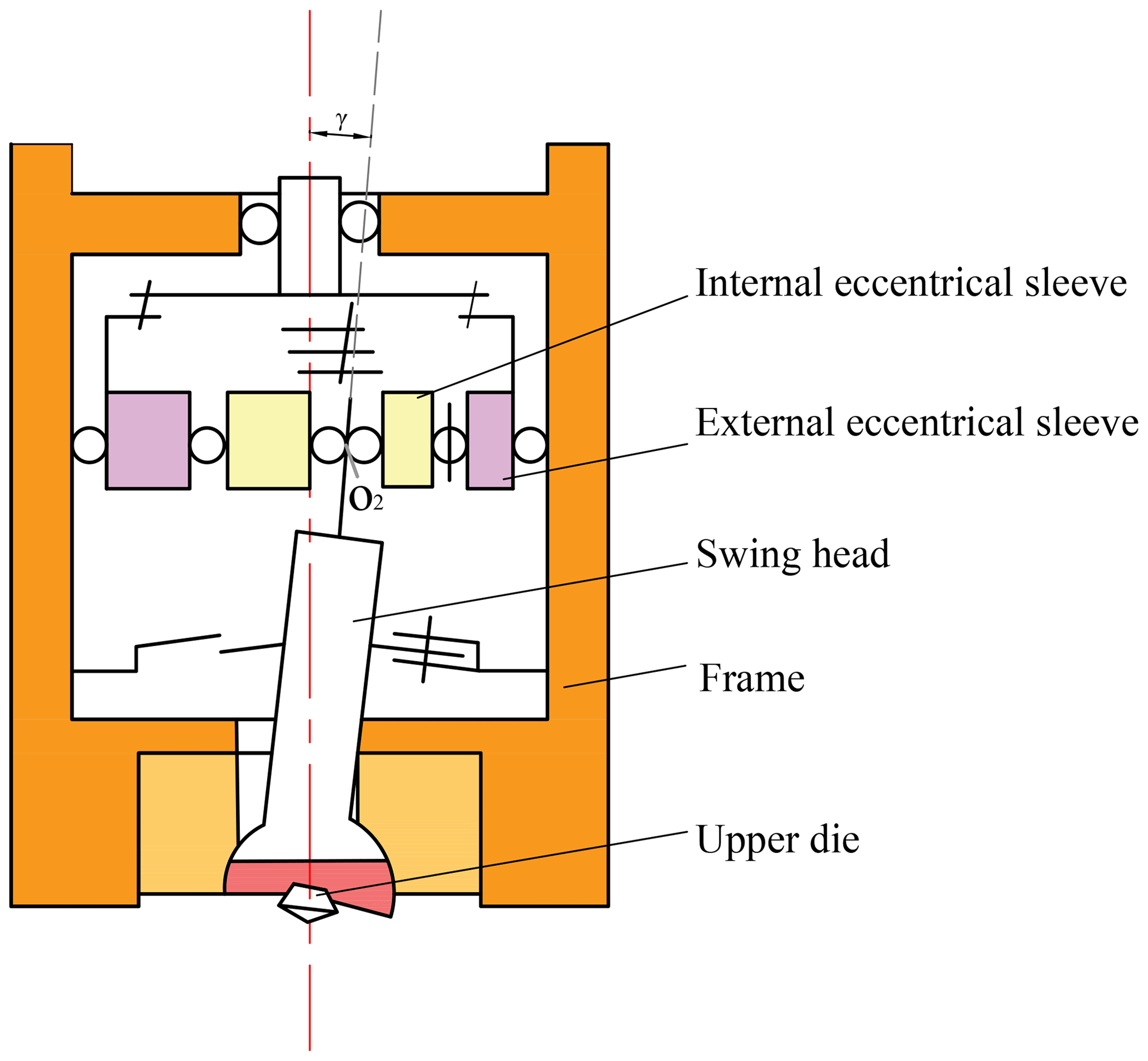
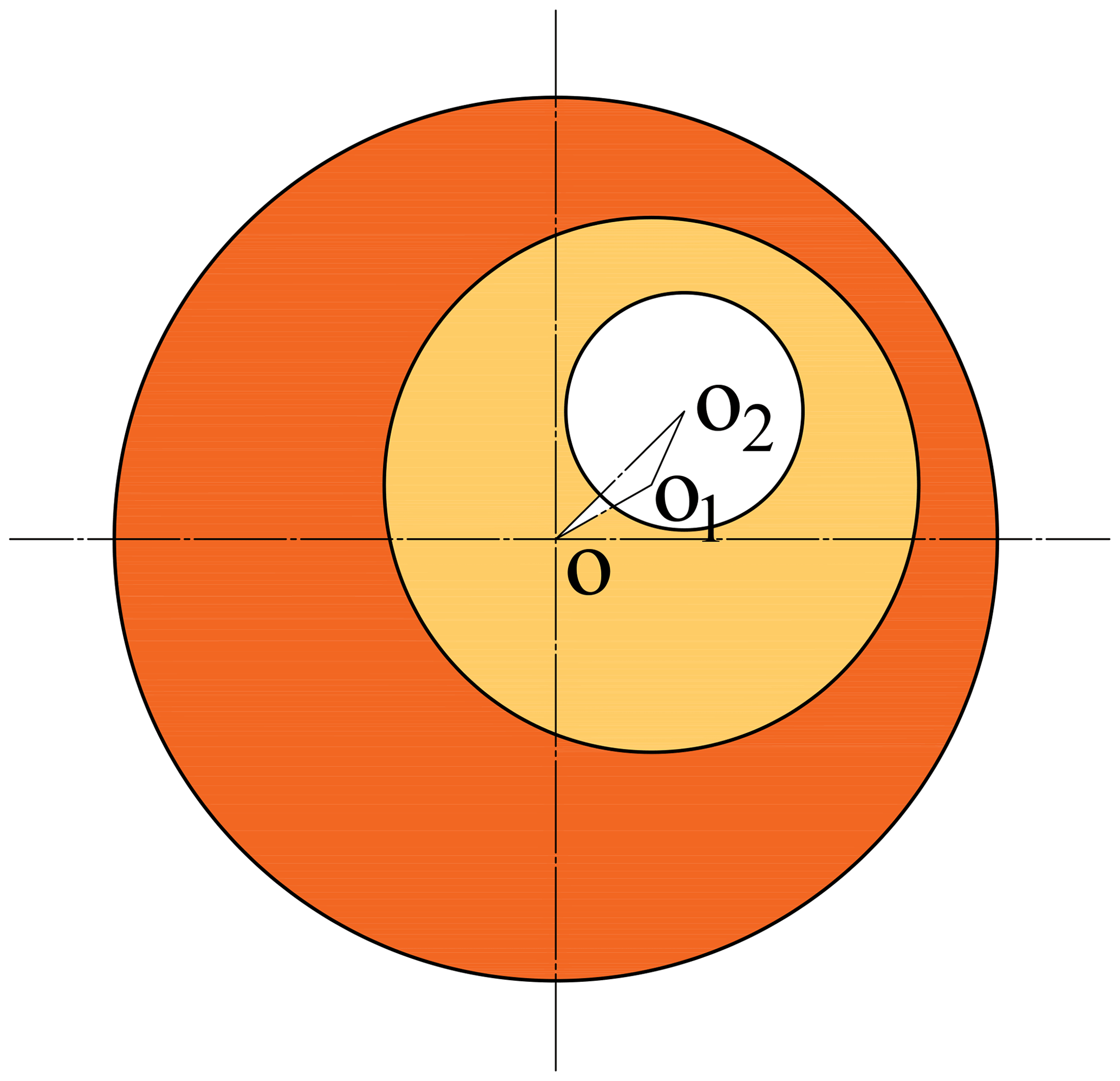
The structure and motion type of the swing head are critical for designing the rotary forging machine. Different structure and transmission form can obtain different motion paths. A schematic of rotary forging machine with double eccentricity sleeve is illustrated in Fig. 1. The relative position and rotation speed of the internal and external eccentricity sleeve determined the various movements of swing head. The movement form of swing head is determined by the internal and external eccentricity sleeve, its positional relationship is shown in Fig. 2.
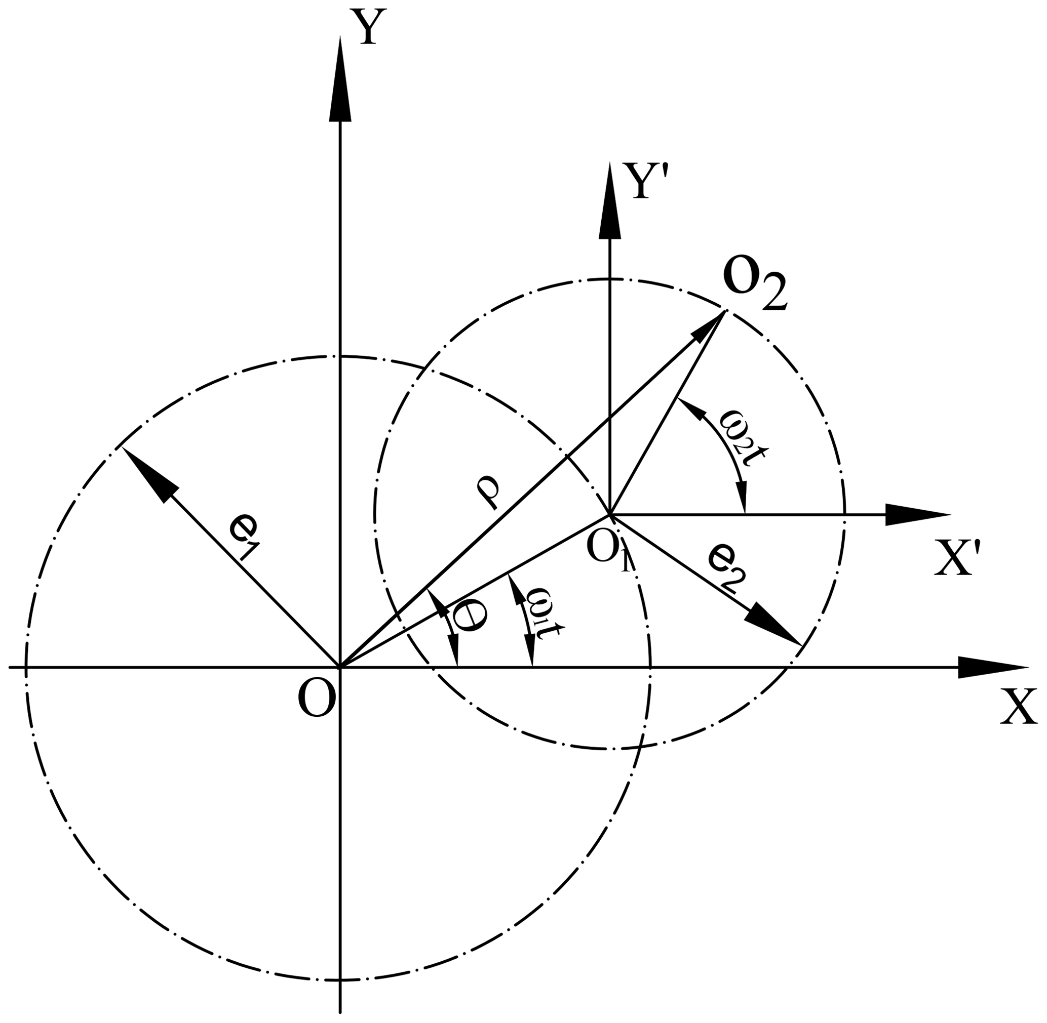
The internal eccentricity sleeve embedded in the external one, |O1O2| and |OO1| is the eccentricity of the internal and external eccentricity sleeve, respectively. Point O2 represents the locus of swing head. Figure 3 illustrates the eccentricity vectors of the internal and outside eccentricity sleeves, |OO1|=e1 represents the eccentricity of the external eccentricity sleeve, |O1O2|=e2 represents the eccentricity of the internal eccentricity sleeve. The position equation of the locus of swing head is obtained as follows:
Polar equation of O2:
e1and e2 is the eccentricity of the internal and external eccentricity sleeve, and mm, ω1 and ω2 is the rotation speed of the internal and external eccentricity sleeve, when ω1=ω2, rad s−1, and when ω1≠ω2, ω1=4π rad s−1, rad s−1. According to Eq. (1), the acceleration of O2 can be deduced as follow:
3.1 Movements analysis when ω1=ω2
When ω1=ω2, the double eccentricity sleeves have rotations with the same rotation speeds and directions. The polar equation of motion curve of O2 can be obtained from Eq. (2):
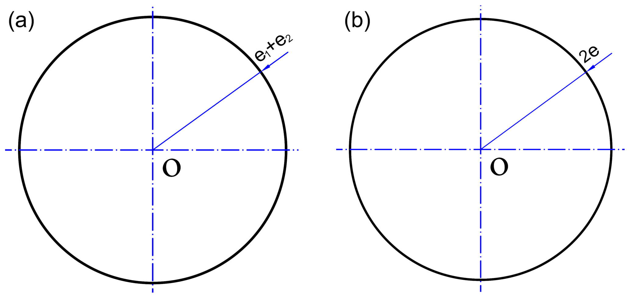
According to Eq. (4), the motion curve of the center point O2 of swing head is a circle, the center point O is geometric center of external eccentric sleeve, the radius is the sum of eccentricity of internal and external eccentric sleeves, i.e. e1+e2, as shown in Fig. 4a.
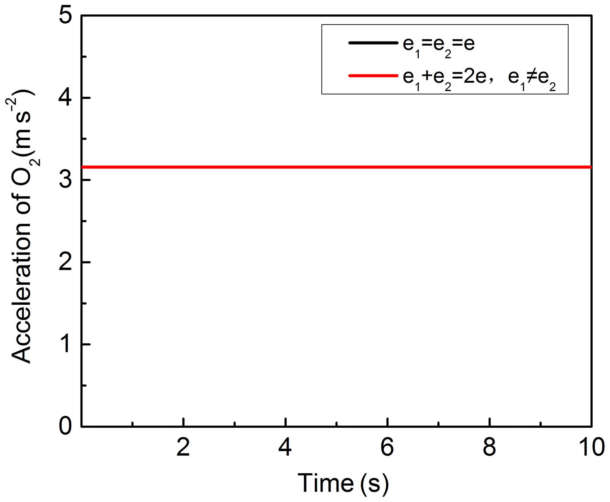
From Eq. (3), when ω1=ω2, the acceleration equation of O2 can be obtained as follow:
When eccentricity of internal and external eccentric sleeves is equal, i.e. , the acceleration equation of O2:
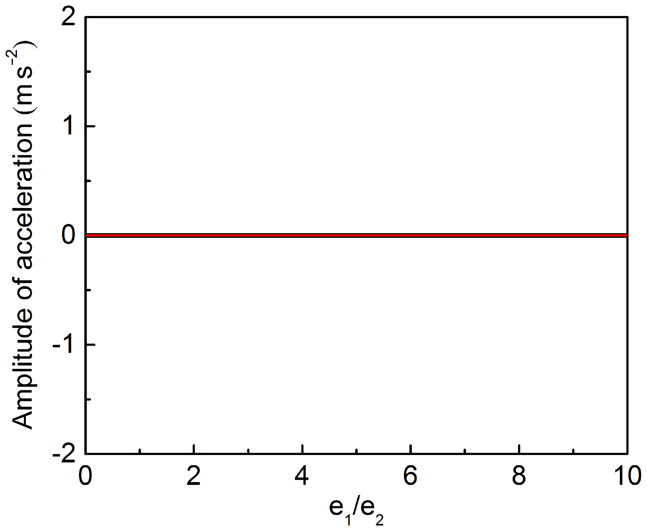
The corresponding acceleration and amplitude curve of O2 are presented in Figs. 5 and 6, respectively. Figure 5 shows that, when ω1=ω2, no matter the eccentricity of internal and external eccentric sleeves is equal or not, the acceleration value always keep constant and the value are equal. Figure 6 reveals the effects of on the amplitude of the acceleration. Figure 6 shows that no matter how the eccentricity of internal and external eccentric sleeves changes, the amplitude of acceleration is always equal to 0.
3.2 Movements analysis when
When , the double eccentricity sleeves have rotations with the same rotation speeds but opposite directions. The polar equation of motion curve of O2 can be obtained from Eq. (2):
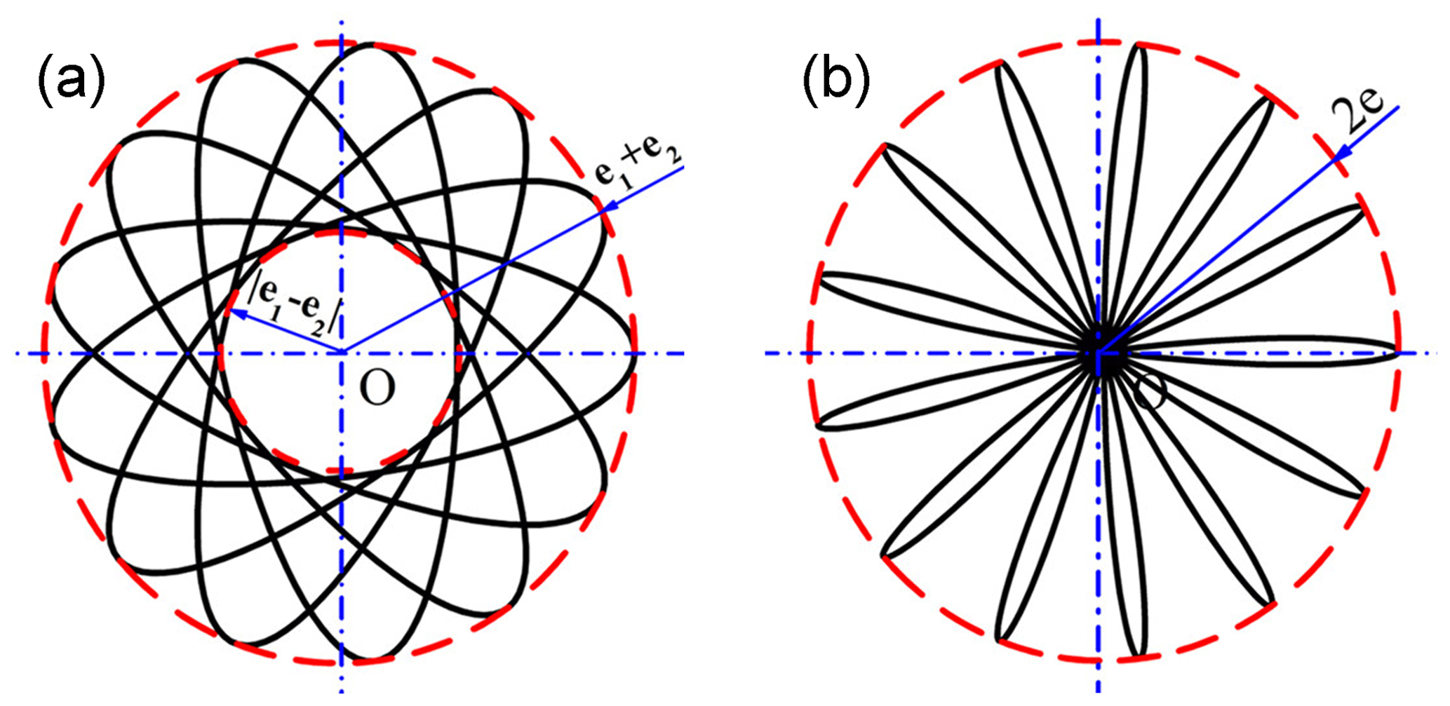
According to Eq. (7), and can be obtained. The motion curve of point O2 is an ellipse with a center point located in the geometric center O of external eccentric sleeve, taking 2(e1+e2) as the long axis and 2|e1−e2| as the short axis, as shown in Fig. 7a.
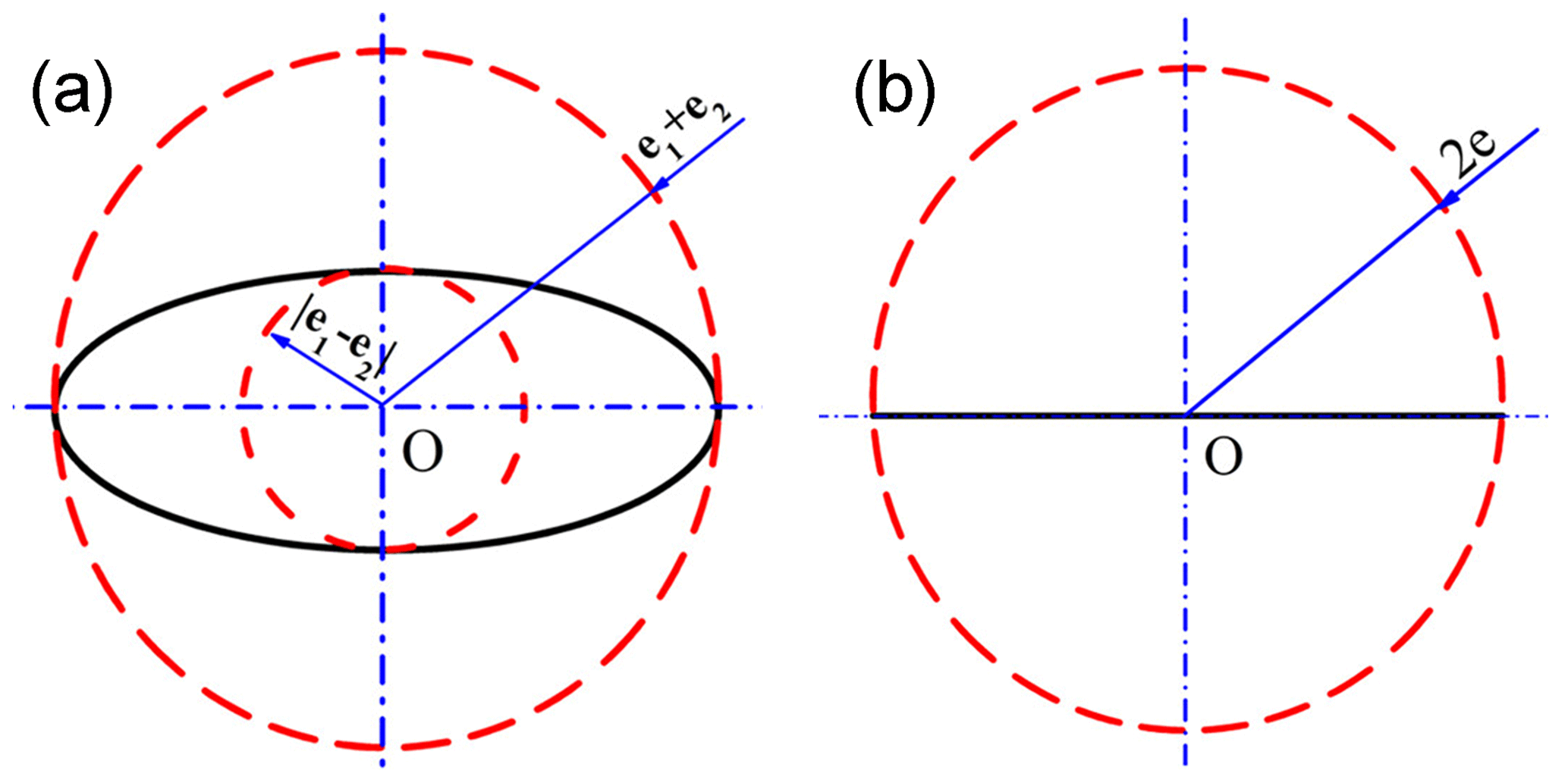
When eccentricity of internal and external eccentric sleeves is equal, i.e. , the polar equation of motion curve of O2:
At this time, the motion curve of O2 is a straight line with a total length of 4e and a middle point located in the geometric center O of external eccentric sleeve, as shown in Fig. 7b.
From Eq. (3), when , the acceleration equation of O2 can be obtained as follow:
, and can be obtained from Eq. (9).
When eccentricity of internal and external eccentric sleeves is equal, i.e. , the acceleration equation of O2:
, and can be obtained from Eq. (10).
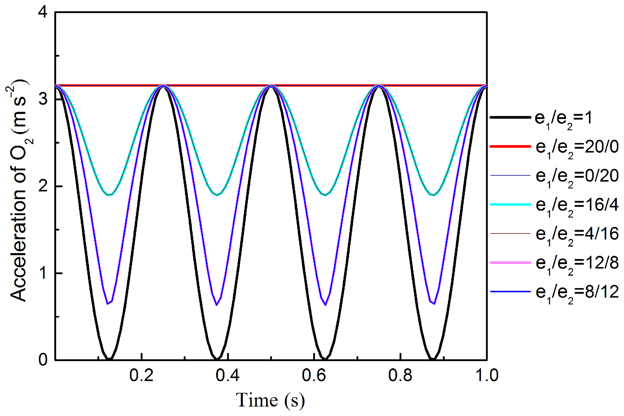
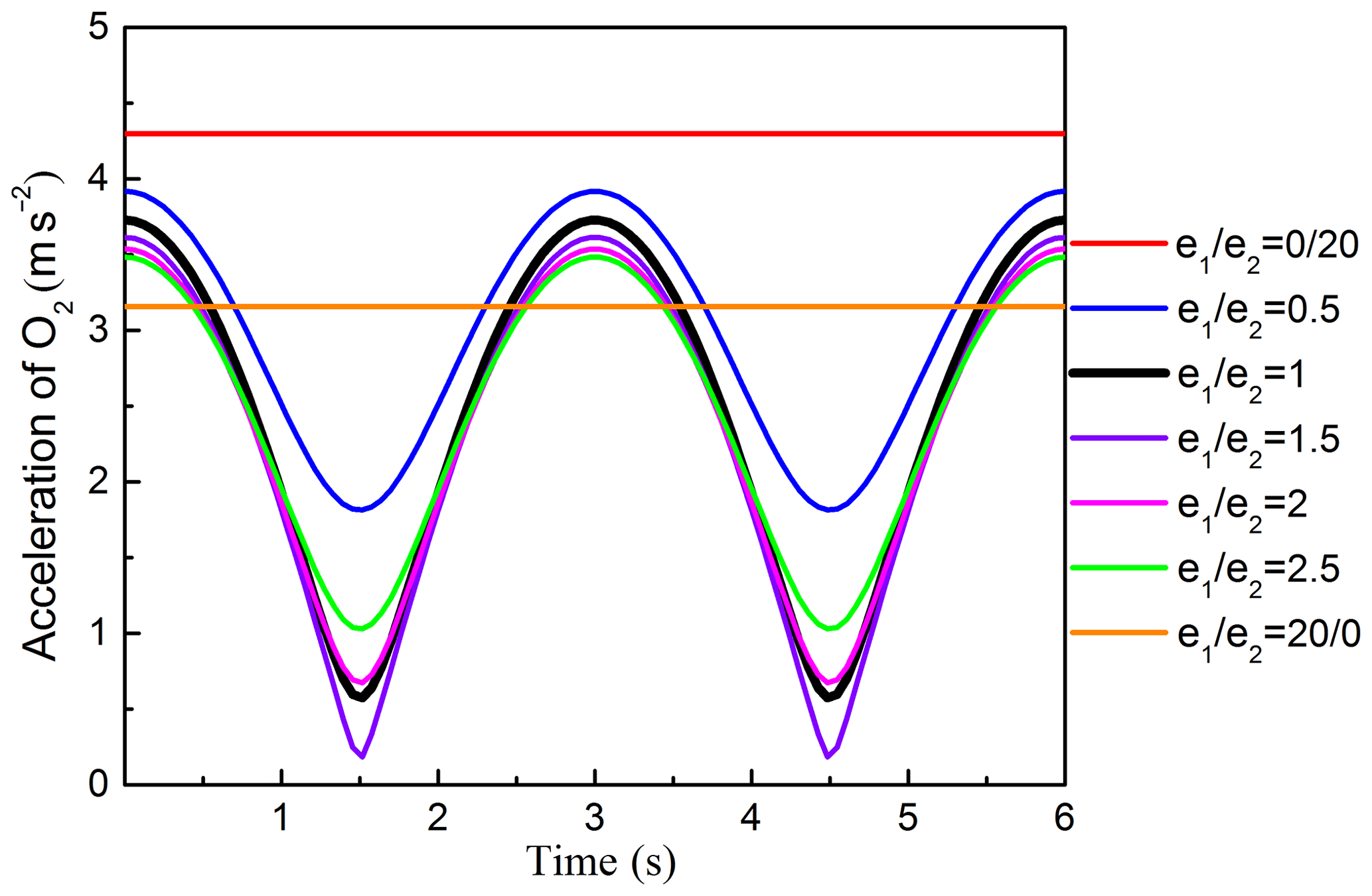
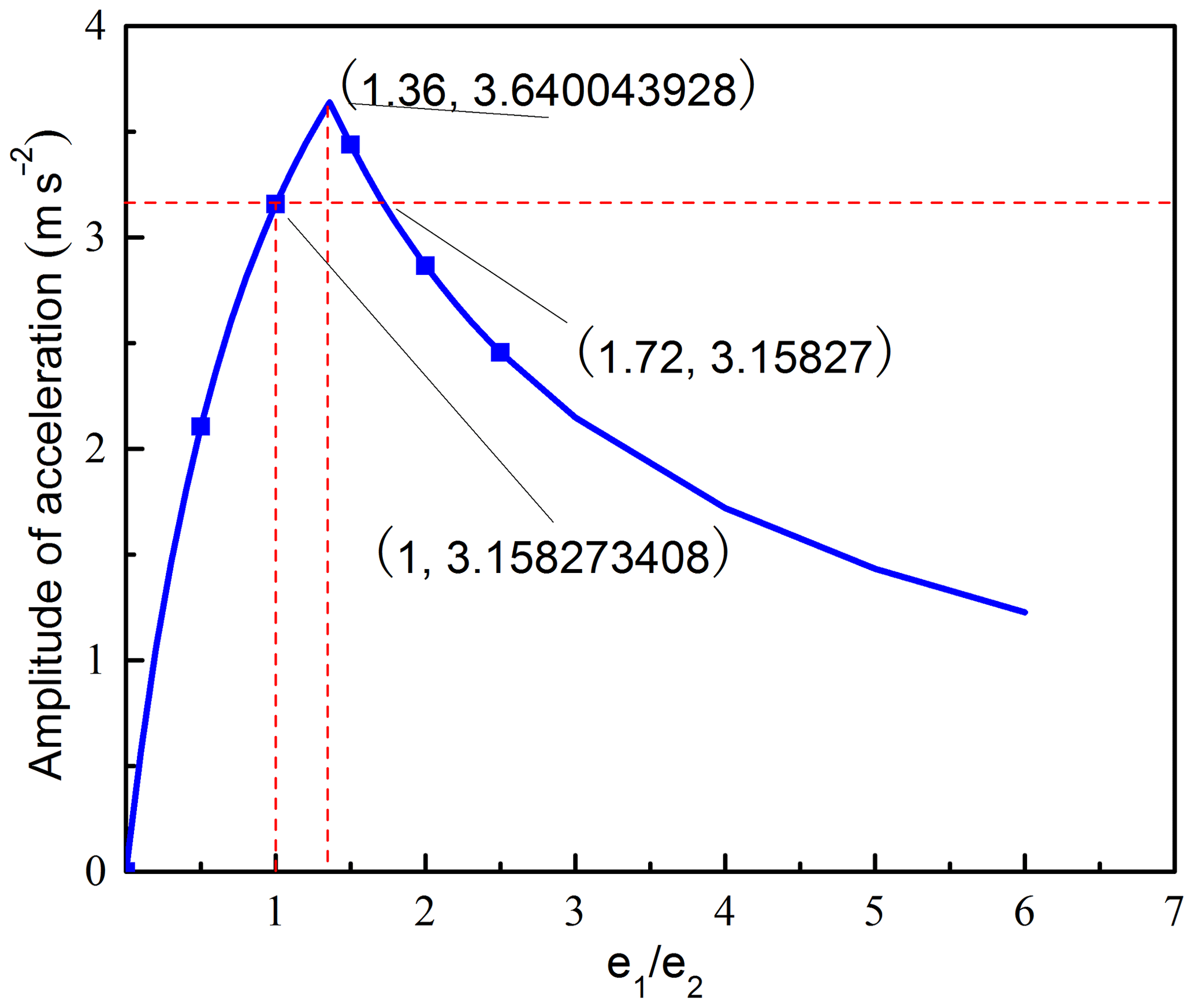
The corresponding acceleration and amplitude curve of O2 are presented in Figs. 8 and 9, respectively. Figure 8 shows that, when , the acceleration curve changed cyclically with cosine function form over time, and the maximum acceleration value is equal no matter the e1∕e2 how to change. When e1 or e2 is equal to 0, the straight line will change into circular line, the corresponding acceleration and amplitude curve are the same with ω1=ω2. When , the acceleration curves will coincide. Figure 9 reveals the effects of on the amplitude of the acceleration. Figure 9 shows that the amplitude curve is a piecewise function curve. When , the curve increases rapidly. When , the curve decreases gradually, the amplitude of the acceleration reaches the maximum value when , and when , the amplitude value is equal.
3.3 Movements analysis when ω1≠ω2 and
When ω1≠ω2 and the double eccentricity sleeves have rotations with different rotation speeds and same rotation directions. The polar equation of motion curve of O2 can be obtained from Eq. (2)
According to Eq. (11), and can be obtained, the motion curve of point O2 is a spiral curve with 2(e1+e2) as external diameter, 2|e1−e2| as internal diameter and a center point located in the geometric center O of external eccentric sleeve, as shown in Fig. 10a.
When eccentricity of internal and external eccentric sleeves is equal, i.e. , the polar equation of motion curve of O2:
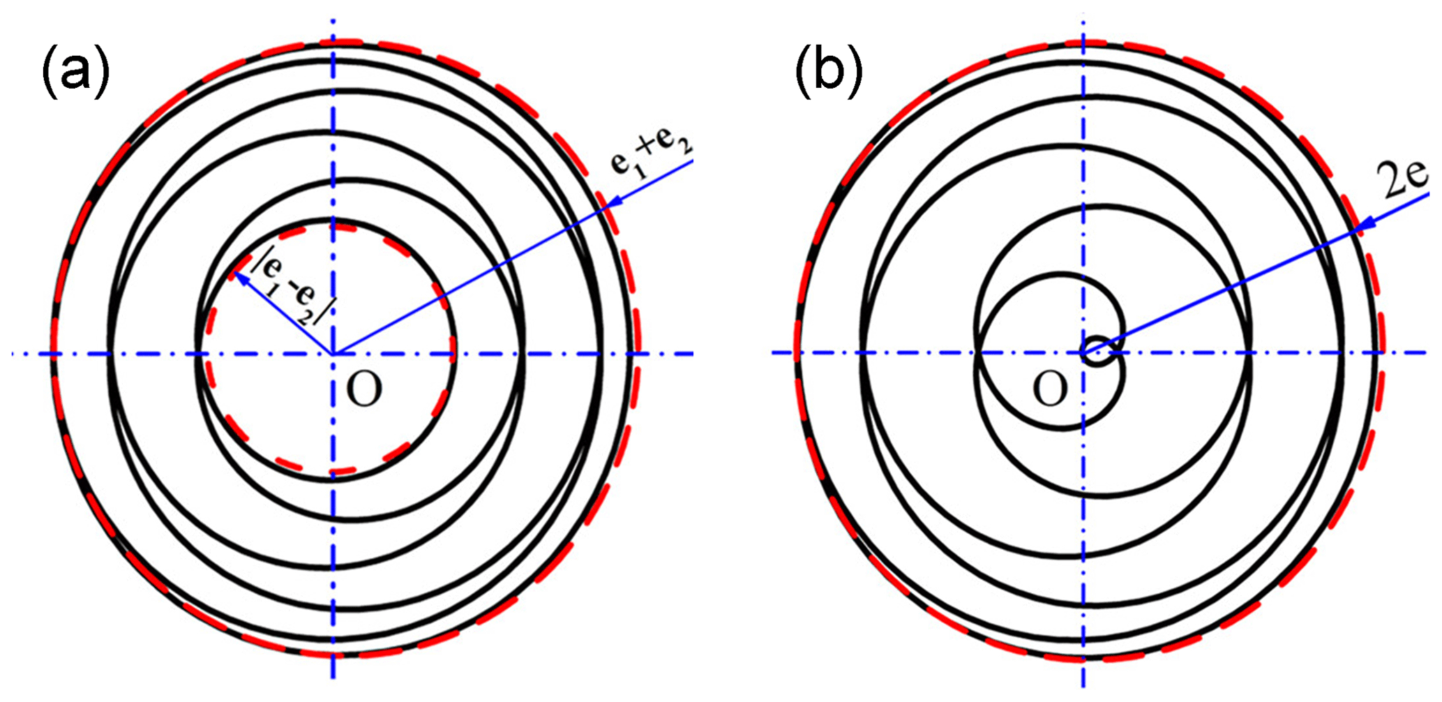
At this time, the motion curve of O2 is also a spiral with 4e as external diameter and the motion curve goes through the geometric center of external eccentric sleeve, as shown in Fig. 10b.
From Eq. (3), when ω1≠ω2 and , the acceleration equation of O2 can be obtained as follow:
, and can be obtained from Eq. (13).
When eccentricity of internal and external eccentric sleeves is equal, i.e. , the acceleration equation of O2:
, and can be obtained from Eq. (14)
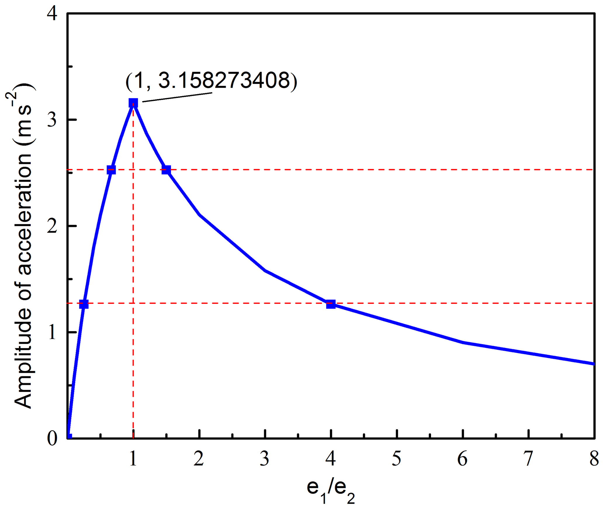
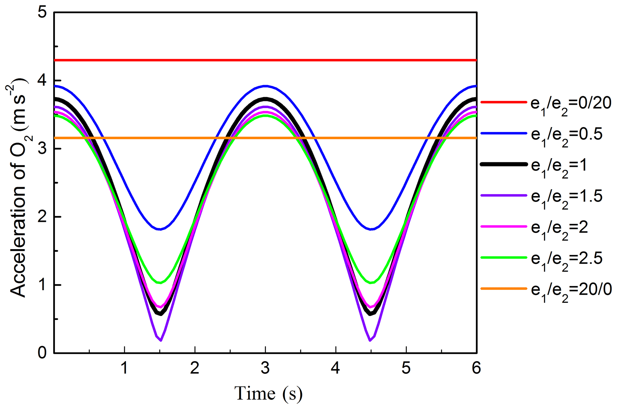
The corresponding acceleration and amplitude curve of O2 are presented in Figs. 11 and 12, respectively. Figure 11 shows that, when ω1≠ω2 and , the acceleration curve changed cyclically with cosine function form over time,and the maximum acceleration value gradually decreases with the increasing of e1∕e2; when e1 or e2 is equal to 0, the spiral curve will change into circle, the corresponding acceleration curve keeps constant value but the acceleration value is different, and the amplitude is equal to 0. Figure 12 reveals the effects of on the amplitude of the acceleration. Figure 12 shows that the amplitude curve is a piecewise function curve. When , the curve increases rapidly. When , the curve decreases gradually, the amplitude of the acceleration reaches the maximum value when , when and , the amplitude of the acceleration will be smaller than that when .
3.4 Movements analysis when ω1≠ω2 and
When ω1≠ω2 and the double eccentricity sleeves have rotations with different rotation speeds and same rotation directions. The polar equation of motion curve of O2 can be obtained from Eq. (2):
According to Eq. (15), and can be obtained, the motion curve of point O2 is a rose with 2(e1+e2) as external diameter, 2|e1−e2| as internal diameter and a center point located in the geometric center O of external eccentric sleeve, as shown in Fig. 13a.
When eccentricity of internal and external eccentric sleeves is equal, i.e. , the polar equation of motion curve of O2:
At this time, the motion curve of O2 is also a rose with 4e as external diameter total and the motion curve goes through the geometric center of external eccentric sleeve, as shown in Fig. 13b.
From Fig. 13, when e1≠e2, the petal of rose curve will be more wider and overlap with each other, but the petal number of rose curve keeps unchanged.
From Eq. (3), when ω1≠ω2 and , the acceleration equation of O2 can be obtained as follow:
, and can be obtained from Eq. (17)
When eccentricity of internal and external eccentric sleeves is equal, i.e. , the acceleration equation of O2:
, and can be obtained from Eq. (18)
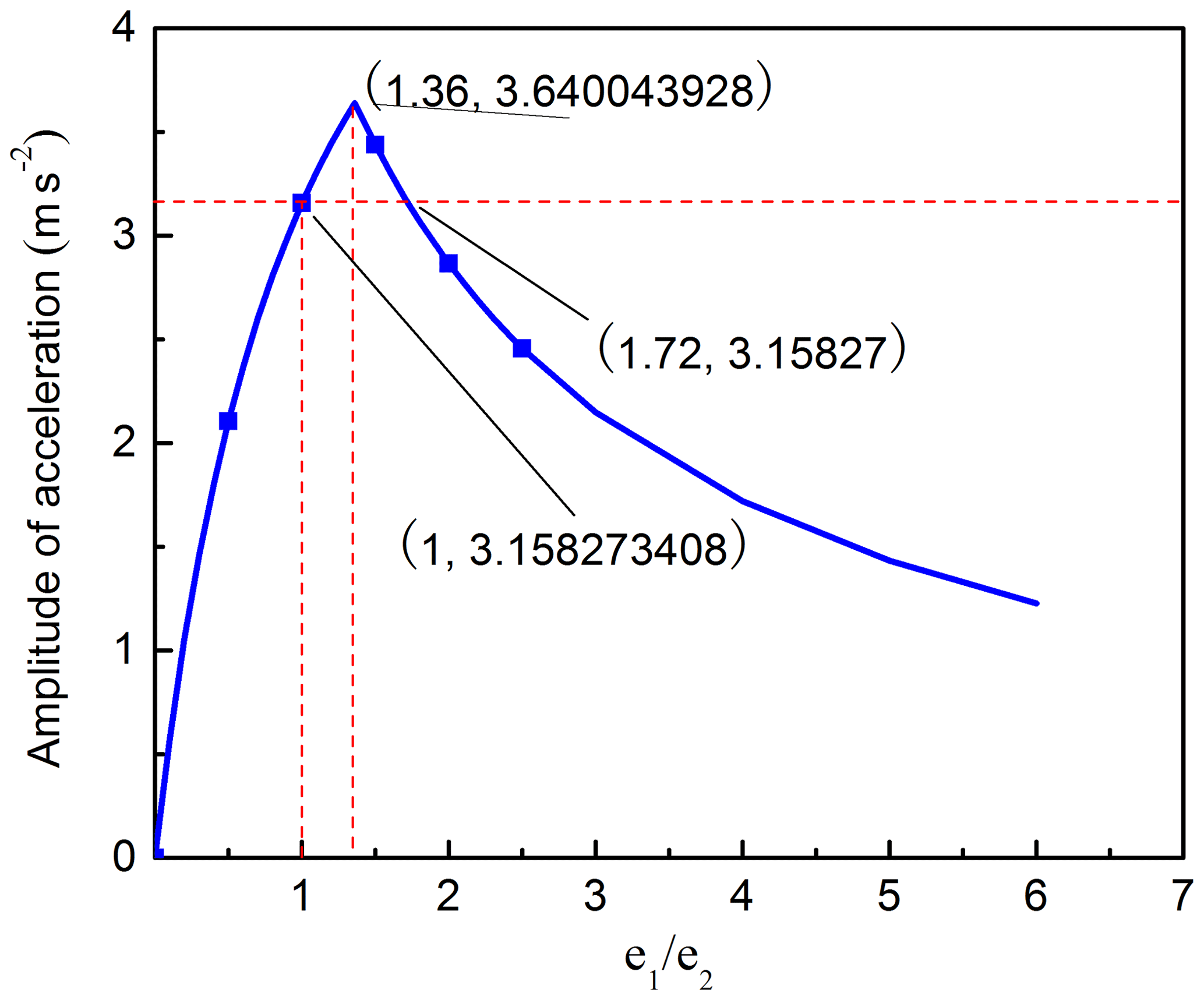
The corresponding acceleration and amplitude curve of O2 are presented in Figs. 14 and 15, respectively. Figure 14 shows that, when ω1≠ω2 and (), the acceleration curve changed cyclically with cosine function form over time,and the maximum acceleration value gradually decreases with the increasing of e1∕e2, when e1 or e2 is equal to 0, the rose curve will change into circle, the corresponding acceleration curve keeps constant value but the acceleration value is different, and the amplitude is equal to 0. Figure 15 reveals the effects of on the amplitude of the acceleration. Figure 15 shows that the amplitude curve is a piecewise function curve. When , the curve increases rapidly. When , the curve decreases gradually, the amplitude of the acceleration reaches the maximum value when , when and , the amplitude of the acceleration will be smaller than that when .
3.5 Comprehensive Analysis
The acceleration and amplitude of the locus point O2 of swing head reflect the movement of the swing head. The greater the acceleration changes, the more unstable the movement of the swing head and the greater shaking the rotary forging machine will be. In order to reduce the vibration of machine, it needs to reduce the maximum acceleration and the amplitude of acceleration at the same time, under the condition that the sum of eccentricity of internal and external eccentric sleeves and rotation speed of double eccentricity sleeve are constant, the corresponding equations as follow:
The relationship of the eccentricity of the internal and external eccentricity sleeves satisfying Eq. (20) can be obtained as follows:
-
When ω1=ω2, no matter the eccentricity of internal and external eccentric sleeves is equal or not, the acceleration value keep constant, and the amplitude of acceleration is equal to 0.
-
When , the maximum acceleration is equal no matter the eccentricity is equal or not, no matter e1>e2 or e1<e2, the amplitude of acceleration when e1≠e2 is always smaller than that when e1=e2.
-
When , according to Eqs. (14) and (15),
when ω1>ω2 Eq. (21) can be obtained as follow:
When ω1<ω2, Eq. (22) can be obtained as follow:
-
When , according to Eqs. (18) and (19), when |ω1|>|ω2|, Eq. (23) can be obtained as follow:
When |ω1|<|ω2|, Eq. (24) can be obtained as follow:
According to the amplitude curves and acceleration curves under different eccentricities, it can be seen that the smaller the e1∕e2, the smaller the amplitude and the maximum acceleration, except for the circular trajectory, under the premise of satisfying the optimization formula. However, the maximum value of e1∕e2 is less than 5 because of the 1∕3 track curve to be maintained during rotary forging. For the optimization of specific part shape parts, several sets of eccentricities are obtained under the requirements of optimization formulas and trajectory curves, The optimal set of eccentricity is determined by studying the influence of several sets of eccentricity on force and energy parameters and deformation uniformity of rotary forging parts.
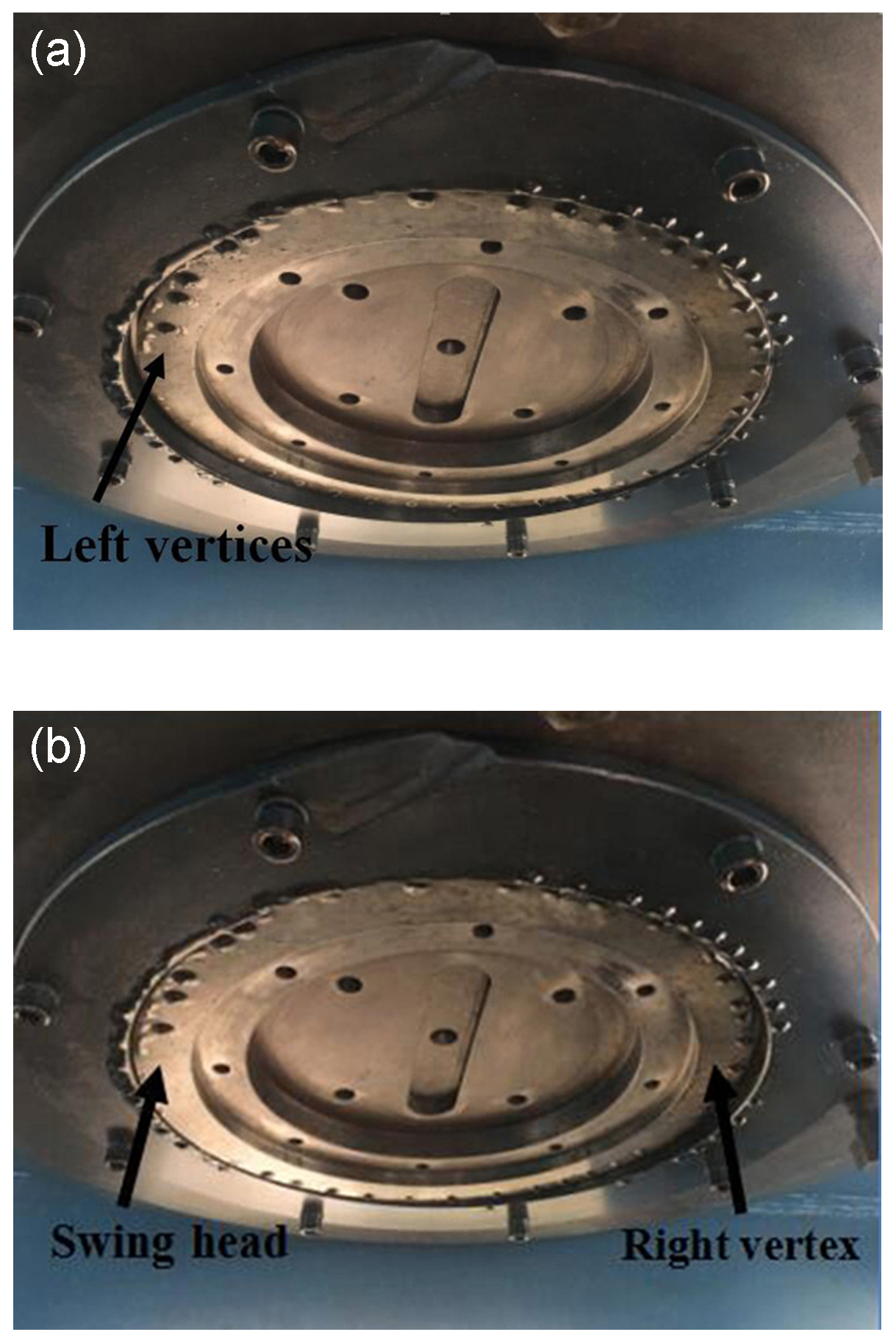
The equipment used in the test is 2600 KN rotary forging machine. When min−1, the trajectory of the swing head was circular. Experiments show that no matter how the eccentricity ratio changes, it has no effect on the motion trajectory of the swing head, and there is no obvious difference between the forged products, which accords with the amplitude variation curve of Fig. 6 deduced by Eqs. (5) and (6) under different eccentricities. When n1=120 r min−1, n2=140 r min−1, the motion trajectory of the swing head was straight line. It was found that when the eccentricity ratio increased gradually from zero, the vibration of the swing head increased significantly. When the eccentricity ratio , the vibration amplitude of the swing head decreases gradually, and the equipment runs more smoothly. When the eccentricity ratio , the vibration amplitude of the swing head is more stable, the product outline is clearer, which accords with the variation curve of the amplitude of Fig. 9 deduced by Eqs. (9) and (10). The swinging motion is shown in Fig. 16.
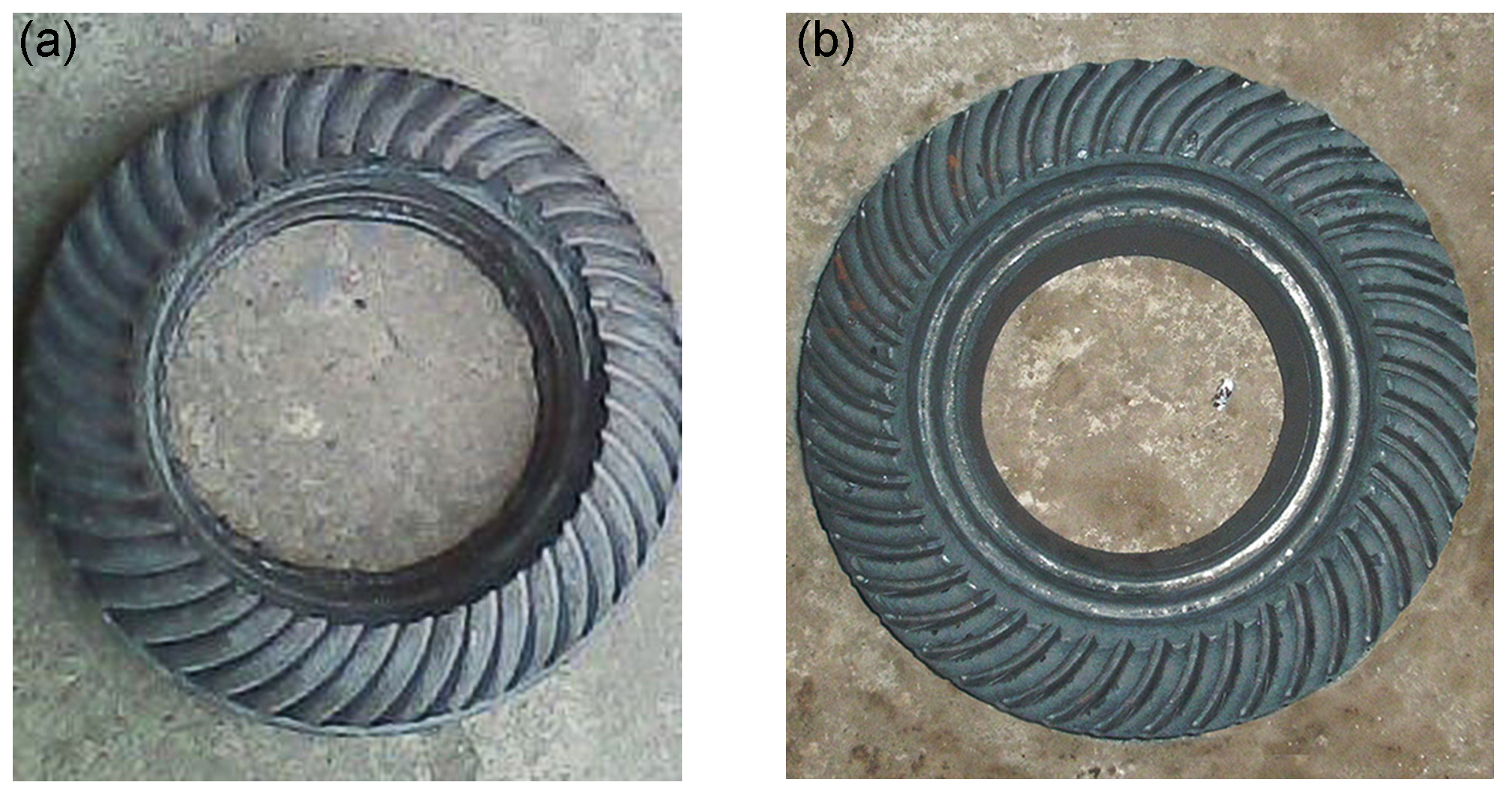
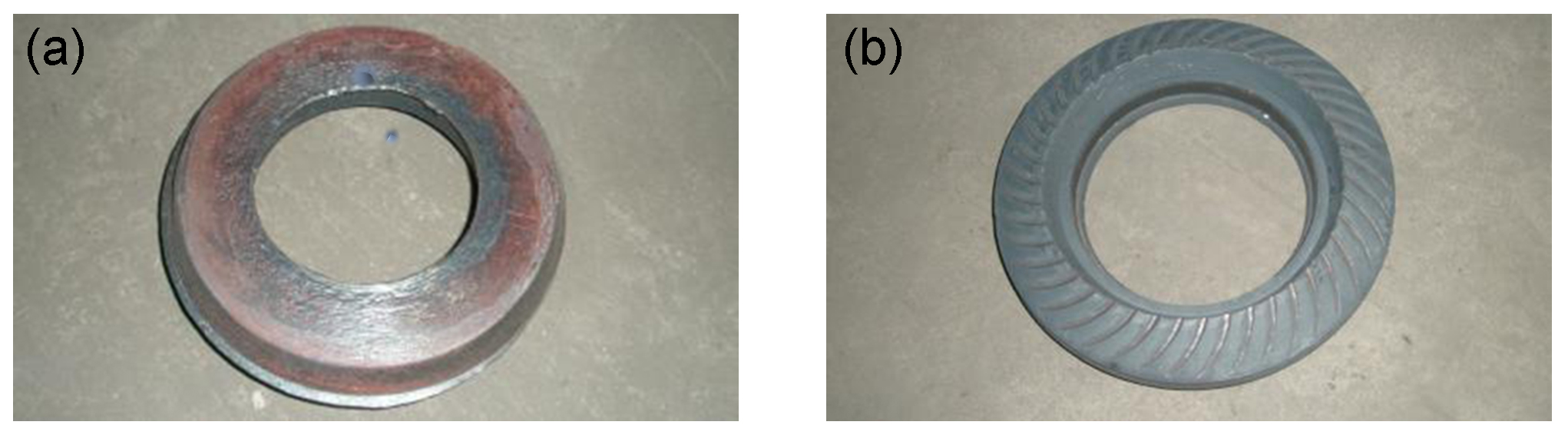
When n1=120, and n1=120, n2=140 r min−1 the eccentricity ratio e1∕e2 increased gradually from zero, the vibration of the swing head becomes more and more obvious. When the eccentricity ratio , the vibration amplitude of the swing head decreases gradually, becomes more stable and the product outline becomes clearer, as shown in Fig. 17. According to the relationship (21) and (23) deduced above, the theoretical calculation value is obtained, and the relative error is about 14 %. The amplitude curves under different eccentricities of Figs. 12 and 15 are basically in agreement with Eqs. (13), (14), (17) and (18). When the eccentricity satisfies the relations (20)–(23) at the same speed of the eccentric sleeve, the experimental results show that the vibration amplitude of the unequal eccentricity is smaller than that of the equal eccentricity, which accords with the inferences of Eqs. (20)–(23). Physical experiments show that the vibration amplitude of the swing head is relatively small when the ratio of eccentricity and rotational speed is appropriate. The driven wheel and spiral bevel gear with clear outline and good dimensional accuracy can be obtained under the spiral and rosette trajectories, as shown in Fig. 18.
This paper studies the influence of the eccentricity of double eccentricity sleeves on the movements of swing head under the condition that ω1, ω2 and e1+e2 are constant. The following conclusions are obtained.
-
When e1≠e2, all the four motion curves will not go through the center point O, the motion curves of swing head moves in the area with O as the center, 2(e1+e2) as external diameter and 2|e1−e2| as internal diameter, and no matter the eccentricity is equal or not, when ω1=ω2, the motion curve of O2 is always a circle.
-
When ω1=ω2, no matter the eccentricity is equal or not, the acceleration and amplitude curve of O2 keep unchanged, the acceleration is constant and the amplitude is equal to 0; When , the acceleration curve changed cyclically with cosine function form over time, and the maximum acceleration is equal no matter the eccentricity is equal or not, when e1 or e2 is equal to 0, the straight line will change into circular line and when , the acceleration curve will coincide and the amplitude value is equal, and no matter e1>e2 or e1<e2, the amplitude is always smaller than that when e1=e2, when e1=e2, the amplitude reach the maximum value.
-
When ω1≠ω2, and ω1≠ω2, , the acceleration and amplitude curve are the same situation, the acceleration curve changed cyclically with cosine function form over time, and the maximum acceleration gradually decreases with increasing e1∕e2, when e1 or e2 is equal to 0, the spiral curve and rose curve will change into circular line, and when e1 and e2 satisfy Eqs. (20)–(23), both the maximum acceleration and amplitude when e1≠e2 are smaller than that whene1=e2.
-
When |ω1|≠|ω2|, the relationships between e1 and e2 are obtained, which can reduce the vibration in rotary forging press, when |ω1|>|ω2|, , when |ω1|<|ω2|, .
Data can be made available upon reasonable request. Please contact Chun Dong Zhu (zcdzcd6252@sina.com).
| O | Geometric center of external eccentricity sleeve |
| O1 | Geometric center of internal eccentricity sleeve |
| O2 | Center point of the swing head |
| e1 | Eccentricity of external eccentricity sleeve |
| e2 | Eccentricity of internal eccentricity sleeve |
| ω1 | Rotation speed of the external eccentricity sleeve |
| ω2 | Rotation speed of the internal eccentricity sleeve |
| a | Acceleration of the center point of the swing head of equal eccentricity |
| a′ | Acceleration of the center point of the swing head of unequal eccentricity |
| A | Amplitude of the acceleration of equal eccentricity |
| A′ | Amplitude of the acceleration of unequal eccentricity |
CDZ proposes method to reduce shaking by changing eccentricity; he did the final examine of the whole paper. XL studied the influence of unequal eccentricity on the movements of swing head obtained the design relationship of internal and external sleeves eccentricity. XJ and YZ performed the experiment to verify the suggested mode.
The authors declare that they have no conflict of interest.
The authors would like to thank the National Natural Science Foundation of China (no. 51875427) for the support given to this research.
This research has been supported by the National Natural Science Foundation of China (grant no. 51875427).
This paper was edited by Xichun Luo and reviewed by two anonymous referees.
Canta, T., Frunza, D., Sabadus, D., and Tintelecan, C.: Some aspects of energy distribution in rotary forming processes, J. Mater. Process. Tech., 80, 195–198, https://doi.org/10.1016/S0924-0136(98)00210-6aC80-81, 1998.
Choi, S., Na, K. H., and Kim, J. H.: Upper-bound analysis of the rotary forging of a cylindrical billet, J. Mater. Process. Tech., 67, 78–82, https://doi.org/10.1016/S0924-0136(96)02822-1, 1997.
Deng, X. B., Hua, L., Han, X. H., and Song, Y. L.: Numerical and experimental investigation of cold rotary forging of a 20CrMnTi alloy spur bevel gear, Mater. Design, 32, 1376–1389, https://doi.org/10.1016/j.matdes.2010.09.015, 2011.
Dong, L. Y., Han, X. H., Hua, L., Lan, J., and Zhuang, W. H.: Effects of the rotation speed ratio of double eccentricity sleeve on rocking tool path in a cold rotary forging press, J. Mech. Sci. Technol., 29, 1619–1628, https://doi.org/10.1007/s12206-015-0333-5, 2015.
Feng, W. C., Yao, W. G., and Jiang, P.: Influence of Eccentricity on Movements of Rotary Head with Double Eccentric Structure in Rotary Forging, Procedia Engineer., 81, 2348–2354, 2014.
Han, X. H. and Hua, L.: Prediction of contact pressure, slipdistance and wear in cold rotary forging using finite element methods, Tribol. Int., 44, 1742–1753, https://doi.org/10.1016/j.triboint.2011.06.034, 2011.
Han, X. H. and Hua, L.: Investigation on contact parameters in coldrotary forging using a 3D FE method, Int. J. Adv. Manuf. Tech., 62, 1087–1106, https://doi.org/10.1007/s00170-011-3867-4, 2012.
Han, X. H., Zhang, X. C., and Hua, L.: Calculation of kinetic locus of upper tool in cold rotary forging machine with two eccentricity rings, J. Mech. Sci. Tech., 29, 4351–4358, https://doi.org/10.1007/s12206-015-0933-0, 2015.
Hawkyard, J. B., Gurnani, C. K. S., and Johnson, W.: Pressure-distribution measurements in rotary forging, J. Mech. Eng. Sci., 19, 135–142, https://doi.org/10.1243/JMES_JOUR_1977_019_032_02, 1977.
Hu, Y. M. and Che, L. C.: Investigation on the motion path of rocking tool in PXW rotary forging press, Forging & Stamping Technology, 3, 25–29, 1993 (in Chinese).
Montoya, I., Santos, M. T., Pérez, I., González B., and Puigjaner, J. F.: Kinematic and sensitivity analysis of rotary forging process by means of a simulation model, Int. J. Mater. Form., 1, 383–386, https://doi.org/10.1007/s12289-008-0075-3, 2008.
Nam, C., Lee, M., Eom, J., Choi, M., and Joun, M.: Finite Element Analysis Model of Rotary Forging for Assembling Wheel Hub Bearing Assembly, Procedia Engineer., 81, 2475–2480, https://doi.org/10.1016/j.proeng.2014.10.353, 2014.
Nowak, J., Madej, L., Ziolkiewicz, S., Plewinski, A., Grosman, F., and Pietrzyk, M.: Recent development in rotary forging technology, Int. J. Mater. Form., 1, 387–390, https://doi.org/10.1007/s12289-008-0076-2, 2008.
Oudin, J., Ravalard, Y., Verwaerde, G., and Gelin, J. C.: Force, torque and plastic flow analysis in rotary upsetting of ring shaped billets, Int. J. Mech. Sci., 27, 761–780, https://doi.org/10.1016/0020-7403(85)90008-6, 1985.
Pei, X. H., Zhou, D. C., and Wang, Z. R.: Some basic problems of the rotary forging and its application, Proceedings of thesecond international conference on rotary metalworking processes, 81–90, 1982.
Rusz, S. and Dyja, H.: The influence of technological parameters on the rotary pressing process, J. Mater. Process. Tech., 157, 604–608, https://doi.org/10.1016/j.jmatprotec.2004.07.121, 2004.
Samoyk, G.: Investigation of the cold orbital forging process of an AlMgSi alloy bevel gear, J. Mater. Process. Tech., 213, 1692–1702, https://doi.org/10.1016/j.jmatprotec.2013.03.027, 2013.
Wang, G. C. and Zhou, G. Q.: A three-dimensional rigid–plastic FEM analysis of rotary forging deformation of a ring workpiece, J. Mater. Process. Tech., 95, 112–115, https://doi.org/10.1016/S0924-0136(99)00268-X, 1999.
Wang, G. C., Guan, J., and Zhao, G. Q.: A photo-plastic experimental study on deformation of rotary forging a ring workpiece, J. Mater. Process. Tech., 169, 108–114, https://doi.org/10.1016/j.jmatprotec.2005.03.003, 2005.
Zhang, M.: Calculating force and energy during rotary forging: Proceedings of the third international conference on rotary metalworking processes, 115–124, 1984.
Zhu, C. D., Guan, Q., and Wang, H.: Twin symmetry roll axial rolling: new method of plastic forming profiles demonstrated using manufacture of spiral bevel gears, Ironmaking Steelmaking, 38, 211–217, https://doi.org/10.1016/j.triboint.2011.06.034, 2011.
Zhu, C. D., Jiang, X., and Dai, T. L.: Research on technology of twin rollers rotary forging of spiral bevel gears, Ironmaking Steelmaking, 42, 632–640, https://doi.org/10.1179/1743281215Y.0000000019, 2015.