the Creative Commons Attribution 4.0 License.
the Creative Commons Attribution 4.0 License.
 | 21 Jun 2019
Research on Influence of Joint Clearance on Precision of 3-TPT Parallel Robot
Chunxia Zhu
Zhiyu Zhao
The error model of the working accuracy of parallel mechanism was established in this paper. The D-H matrix method and error independent method were used to analyze the clearance error of mechanism joint based on the inverse position kinematics solution. The theoretical model describing the position error of the moving platform position error affected by its joint clearance was developed when the moving platform was parallel to fixed platform in the ideal state; the clearance error model of 3-TPT Parallel mechanism was established based on D-H matrix method and error independent method while the joint clearance error source was given. The effect of joint clearance error on the working accuracy of 3-TPT parallel mechanism was analyzed by Monte Carlo method. The effect of posture error due to revolution of the moving platform about coordinate axis on the error of parallel mechanism was simulated and analyzed based on D-H matrix method in the non-ideal state.


In recent years, with the extensive application of parallel mechanism, the research on parallel mechanism is also increasing, but the accuracy of the solution of parallel mechanism has not been improved. Component parameters and mechanism control system are the main references and index of accuracy design of parallel mechanism, which influences the machining quality of parts to a certain degree (Zhu et al., 2017; Akhadkar et al., 2018a). With the increasing demand of machinery manufacturing industry, automatic production and processing quality has been improved. It is of great importance to make the error of parallel mechanism to achieve optimal and improve the processing capability of manufacturing organization (Zheng et al., 2016; Akhadkar et al., 2018b; Yan et al., 2015).
It is an important problem that one of each input structure error was not cumulative and each branch error can cancel others out in the machining accuracy of parallel mechanism. But when it is applied on the actual production, due to the fact that the configuration of mechanism is simple, it is found that the machining accuracy of parallel mechanism is quite different from that of machine tool based on series mechanism (Liang et al., 2012). With the wider application of parallel mechanism in our life, the requirements of working accuracy in the design of parallel mechanism have become increasingly demanding (Zaeh and Siedl, 2007).
The research on parallel mechanism is becoming an important part of design for parallel mechanism as many experts and scholars are focusing cumulatively on its accuracy problems. Considering that the parts of the parallel mechanism must be flexible in the working space, there should be a certain gap between the movements of adjacent joints to ensure the normal operation of mechanism (Subudhi and Morris, 2002). With the existence of the joint clearance, the actual working accuracy of the parallel mechanism is rather low, which affects the accuracy and performance of the mechanism (Wu et al., 2013; Zhang et al., 2013). Therefore, the research on the influence of clearance on accuracy of parallel mechanism cannot be ignored. And it will play a significant role in the error analysis of parallel mechanism.
Joint clearance is one of the main factors that lead to the decrease of the performance of the mechanism, which leads to the position and attitude error, impact and wear of the end effectors. The mechanism designers try to eliminate the clearance and the extra degree of freedom by the pre tightening method, but it can lead to the difficulty of assembly, and the higher accuracy and manufacturing cost are needed. When the body is under the constraint, it is possible to lose the degree of freedom so that it cannot be installed.
In the past research of the effect of clearance on the mechanism, the main application methods are the matrix method, the vector method and the error independent action principle method (Mihai and David, 2010). They have a strong commonality in the analysis of clearance impact on the mechanism, and are suitable for the analysis of clearance error for most mechanism (Amir and Alireza, 2015).
A branched chain of 3-RSR Parallel Robot was studied in the reference (Hiwa and Gholamhasan, 2014), the platform motion relative to the fixed plat-form position and orientation relation matrix was established by using D-H matrix, the mechanism structure manufacturing errors to the end effect or error mapping model was deduced by adopting the error sources of differential method. The paper (Mikhael et al., 2014) carried out a research on the crank slider mechanism, they established the function relation between the slider motion and the center distance of the crank by using the vector method; Literature (Singhee and Rutenbar, 2010) built error model of PSS parallel mechanism by using vector method, the calibration values of the mechanism were obtained by using calibration algorithm based on initial values and according to the model error mechanism error source on the moving platform output end pose. Reference (Piras et al., 2005) quantitatively analyzed the effect of component error of the whole mechanism of hybrid five axis parallel mechanism by using the independent principle of error and taking into account component manufacturing and assembly errors.
The clearance error of the parallel mechanism is the output synthesis error of the working point of the moving platform which is caused by the joint clearance of each branch. Compared to the error of the traditional serial mechanism, the error of the individual branches of parallel mechanism will not be linear cumulative. So its research methods and final results are also very different from the series mechanism.
The first step of error modeling of parallel mechanism is to establish the error model of the output point of the moving plat-form. Existing method for error modeling of parallel mechanism is mainly considering the effect of each input error on final output error while some dynamic factors are existed such as no work load, which belongs to the field of static error analysis.
Experts and scholars in many countries have carried out a wide range of researches on clearance error. The reference (Liang et al., 2012) put forward a new method to analyze the impact mechanism of motion pair with clearance for the space mechanism, which can achieve a more accurate evaluation. This method is suitable for the plane or space, open or closed chain structure, but not suitable for over constrained mechanism. It belongs to the kinematic method and directly determines the worst contact condition of the motion pair with clearance, which is the cause of the maximum position error (Amir and Alireza, 2015). The reference (Huang et al., 2011) analyzed the error of parallel manipulators with a chain gap and put forward a general error prediction model that the maximum error prediction problem represented a standard convex optimization problem, which can be used for planar or spatial, constraints or non over con-strained manipulators. Taking the robot, parallel manipulator with parallel edges and the translational degree of freedom as an example, this paper gives the derivation method of the maximum position error in the general configuration and the given working space. Reference (Dai et al., 2017) proposed a nonlinear error equivalent method to analyze the pose error of a parallel robot with joint clearance. And it could be used in estimating the calibration error, tolerance design and trajectory planning of a spherical joint and slide pair comprised parallel robot. Reference (Cavalieri and Cardona, 2018) proposed a new element for modeling three-dimensional revolute joints with clearance. The equations of motion are solved with a non-smooth generalized-α time integration scheme, in which the constraints at velocity and position levels are satisfied exactly without requiring the user to define any penalty parameter.
However, a few of scholars analyzed mechanism accuracy and position error of parallel mechanism which affected by the chain clearance (Liang et al., 2012). One of the main sources of error of parallel mechanism platform is the installation error of parts manufacturing. And the joint clearance error of the component is an important component for the structural parameter errors. In order to improve the accuracy of such mechanism, the possible errors were evaluated and on-line error compensation was carried out by control system for the purpose of accuracy machining. The error model of the working accuracy of the parallel mechanism was established in this paper. Through the analysis of the inverse position kinematics solution, the D-H matrix method and error in-dependent method were used to analyze the clearance error of mechanism joints. The theoretical model describing the position error of the movable-platform position error affected by its joint clearance was developed when the movable-platform was parallel to fixed-platform in the ideal state; the 3-TPT Parallel mechanism clearance-error model was established based on the D-H matrix method and the error independent method when the joint clearance error source was given. The Monte Carlo method was used to analyze the effect on the 3-TPT parallel mechanism working accuracy caused by the joint clearance error. The effect of the posture error due to the revolution of the movable platform about coordinate axis on the error of the whole parallel mechanism was simulated and analyzed based on D-H matrix method in the non-ideal state.
2.1 Introduction of 3-TPT parallel mechanism
3-TPT parallel mechanism is consisted of fixed platform, mobile platform, 3-driven links (2-Hooke and 1-Prismatic pair) and constrain mechanism, as shown in Fig. 1. The coordinate systems of OB-XYZ and OB-XYZ are established respectively in the fixed platform and the mobile platform. The origin of the fixed platform coordinate system is coincident with the fixed platform center, and the Z axis is vertically downward and the Y axis through over the platform hinge point B1. Positive X-axis and fixed platform B1B2 edge intersect each other; and origin point of moving coordinate system OP-XYZ and the center of moving platform are coincided, Z axis vertically downwards. X plane of OP-XYZ is parallel to Y plane of OB-XYZ. The radius of the fixed platform is R and the radius of the moving platform is r. BBi and PPi are Coordinate vectors in the respective coordinate system of the fixed platform and the moved platform respectively. BPi is the connection point of the moving platform and the coordinate vector in the fixed coordinate system. BtP is the coordinate of the center point of the moving platform in the fixed coordinate system. is the length error of link of parallel mechanism, is the position error produced by the hinge center point position error in the ideal state, is the pose error of the moving platform, is the center point of the moving platform, which is the working position error.

2.2 Clearance error model of 3-TPT parallel mechanism with matrix method
The inverse solution equations of the mechanism are expressed as follows:
Where is the unit vector of the extension direction of the telescopic rod, and is the transformation matrix of the coordinate system of the moving platform with respect to the coordinate system of the fixed platform.
Differential equation of Eq. (1) is given:
The movement platform of 3-TPT parallel mechanism moves in parallel to the fixed platform without rotation. So then the following equation can be expressed as follows:
Eq. (3) multiplied by the extension direction of the telescopic rod ki on both sides of the same time, then the following equations can be got as , , so,
And at the same time, considering the influence of the gap on the hinge center, the above formula is modified. Which,
In which is a space vector of fixed platform hinge on the coordinates of fixed platform, is the space vector of hinge of moving platform on the coordinates of moving platform. Integrated Error from three directions, the above Eq. (6) can be written as,
Where,
The equation Multiplies N−1 on both sides
Eq. (8) is the mathematical error model of the center of the moving platform with the gap based on the D-H matrix method. In which is the joint clearance error of the source of input error, is the work position error that is the center of the moving platform.
2.3 The error model based on the principle of independent action
Independent principle of error is that the effect on moving platform working point of a link error of parallel mechanism is considered separately, and other sources of error has nothing to do with it, then the error function is established separately based on the influence of each error source, and the influence on the accuracy of error sources to the working position is derived. Based on the principle of error independent action, the working error of the moving platform is formed by the superposition of the position error of fixed platform and the hinge point of the moving platform, which are generated by the hinge clearance. The platform position error equation is as follows.
The position error of the 3-TPT parallel mechanism moving platform can be obtained by the differential equation of the Eq. (9),
The other errors of the mechanism are not considered at the same time, the length of the error is 0, that is , so only analyzing the clearance of ring gap, then above Eq. (10) can be expressed by following equation.
Where and are the error transfer function of the fixed platform and the moving platform respectively.
Based on the principle of error independence, the influence of the clearance of the hinge point on the moving platform is analyzed, and It is assumed that there is no position error of other hinge points on the moving platform. The position error of the moving platform caused by the clearance of the moving platform can be added together with the position error of the moving platform.
In the fixed coordinate system, is the coordinate of the base platform hinge point Bi in fixed coordinate system, is the coordinate of moving platform hinge point Pi in fixed coordinate system coordinates. Then the three links of parallel mechanism could satisfy all the condition in any position.
If there is no gap between the hinge points of the moving platform, the motion of the moving platform is moving relative to the fixed platform, and the error of the moving platform is caused by the error of the hinge point of the fixed platform. Then the Eq. (12) is derivative as following (),
Since the fixed platform hinge gap is the only factor to be considered, the motion varieties of moving platform are the same. So the error of the moving platform is equal to the small change of the hinge point on the moving platform. So
It is expressed based on 3-TPT Parallel Mechanism as follows:
so
That is
If assumed that other hinges don't exist gap, that is other hinges points are in the right position relative to the fixed platform, let i=1, then Eq. (15) can be written as follows,
It can be known by the kinematic analysis of the mechanism that if |W|≠0, then W is reversible, so,
In the same way, the influence on the position error of the moving platform of other two hinge clearance of the fixed platform are obtained shown as following.
The error influence coefficient of the hinge point position error of the fixed platform is respectively shown as follows,
The above combined error transfer function is the position error model of the hinge point of fixed platform. is the transfer function of clearance error for Hooke joint. Because of the mutual motion of the moving platform and the fixed platform, it can be known that the influence of the gap error between the two ends of each drive rod on the output position error is equal to the influence of the Hooke joint, so
If the gap error of each Hooke joint is known, then the end output position error caused by the clearance error of Hooke joint can be obtained. In the present work, because the error of joint of the mechanism is caused by the manufacturing and installation process, it is considered that the gap error of the structure is in accord with the normal distribution, At the same time, the attitude error of the moving platform is assumed to conform to the normal distribution. Then the effects of above two errors on the overall error of the mechanism are simulated. At last, the accuracy of the mechanism is obtained considering the clearance and the attitude error of the moving platform.
2.4 Random sampling of joint clearance error
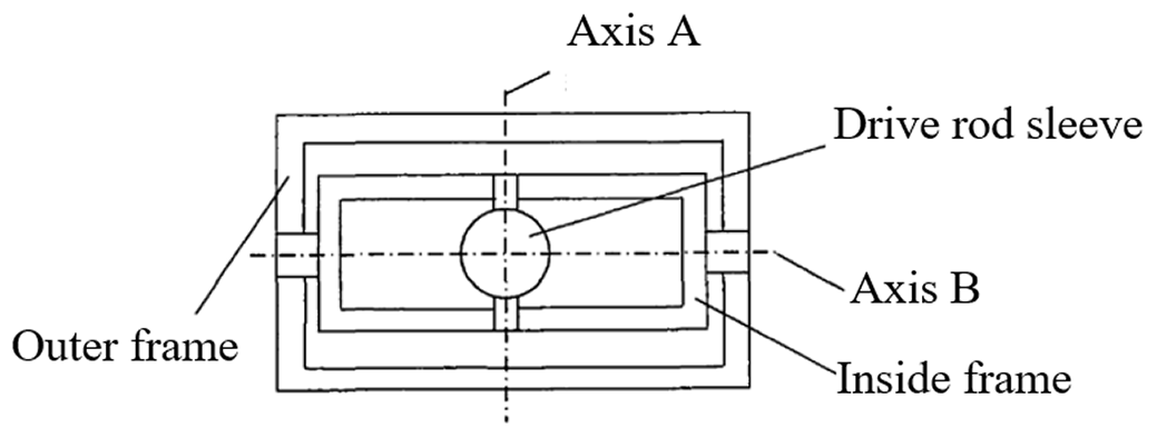
The Hooke joint of 3-TPT mechanism is designed as a split-type with inner and outer frame structure which rotates along two separate axes for accomplishing two-dimensional rotation of the connection of adjacent members. The structure of Hooke joint is shown in Fig. 2. The Hooke hinge of 3-TPT parallel mechanism has the inner and outer frame structure. The outer frame and a fixed platform are fixed together, and the inner frame rotates around a shaft frame, the driving rod sleeve can rotate around the inner frame by an axis of rotation, and the shaft frame and the axis of rotation can form a cross shaft, and that the driving rod sleeve axis, the shaft frame and the axis of rotation are mutually orthogonal. So there are two rotational degree of freedom around the axis A and axis B.
Since there are clearance errors in two mutually perpendicular directions for Hooke Joint, they cannot be arbitrarily superposed each other. Therefore it is necessary to consider the output end position error caused by Hooke joint clearance error in two directions respectively. In order to more directly and clearly express the gap error in two directions, a coordinate system O′- is set up at the intersection of the two axes of the hook hinge. Where, the plane is parallel to the plane of the fixed platform, X′ is parallel to the B axis, μ is the angle between X′ and the X axis in the base coordinate system, Y′ is parallel to the A axis, and point to the origin of base coordinate system. Then the transform matrix which the coordinate system O′- relative to the fixed platform coordinate system O-XYZ is expressed as:
Then the position transfer matrix of each Hooke hinge can be obtained from the above formula.
δu is the joint clearance between Hooke joint outer frame and a shaft A on each platform, in order to consider the biggest impact caused by the error, namely, the probability that the centre of each axis of hook joint outer frame falls on an arbitrary point which on the circle with a radius of δu is equal, and the angle within the range of (0,2π) obeys uniform distribution. The outer ring joint clearance δu and the angle αu are independent each other, after respectively getting the outer ring joint clearance and the angle of the sample values αu, the axis clearance of Hooke joint outer frame can be obtained by following equations.
Similarly, δu′ is the joint clearance between Hooke joint inner frame and a shaft B on each platform, the probability that the centre of each axis of hook joint inner frame falls in an arbitrary point which on the circle with a radius of δu′ is equal, and the angle αu′ within the range of (0,2π) obeys uniform distribution, the inner ring joint clearance δu′ and the angle are independent each other, after respectively getting the inner ring joint clearance and the angle of the sample values, the axis clearance of Hooke joint inner frame can be obtained by fowling equations.
Then the relative error of the joint clearance of parallel manipulator of each Hooke joint with respect to the base coordinate system is
3.1 The simulation analysis for the error of the joint clearance by matrix method
As the mentioned above, the effect model of clearance error of parallel mechanism on work accuracy has been built. In or-der to have a more intuitive response to mechanism clearance effect on the accuracy of the mechanism, the error model analyzed above is simulated and carries out the relevant analysis on accuracy of 3-TPT parallel mechanism. Because the clearance of inner and outer ring of Hooke joint of 3-TPT Parallel Mechanism belongs to machining error with very strong randomness, the clearance error influence on accuracy can be significantly described by using Monte Carlo random experiment method, thus achieving the analysis of the error characteristics.
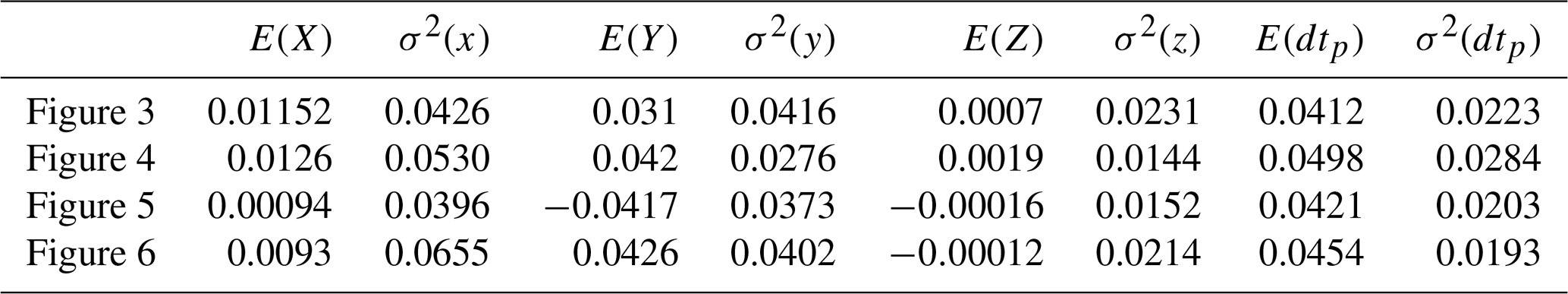
Table 1The statistical parameters of position errors influenced by joint clearance in different positions using matrix method.
In this paper, due to the fact that the joint clearance error belongs to errors generated in the manufacturing and installing pro-cess, the clearance error of mechanism is similar to that of normal distribution, it also assumes that the posture error of moving platform conform to normal distribution. The simulation will be carried out by considering the effect on working accuracy of clearance error and posture error.
Taking the 3-TPT parallel mechanism developed by Northeast University as an example, the error analysis of the mechanism is carried out. The parameters of each component of the parallel mechanism are shown as follows. c=400 mm, R=650 mm, r=250 mm. In order to analyze the influence of the joint clearance error on the position error of the moving platform more directly, the inner and outer ring clearance of Hooke joint are assumed as mm. And the clearance distribution angle αu accords with to uniform distribution in the range of (0,2π), and the position synthesis error of the moving platform is
The position error (position error of the moving platform) is outputted by using the D-H matrix method for Monte Carlo simulation in this part. As a sample size of 800, based on the D-H matrix method, the simulation results of error of mechanism that affected by joint clearance are obtained in the XYZ three directions and the Synthetic direction.

Figure 3Frequency histogram of position error on working point in (0, 0, 1000) by matrix method.

Figure 4Frequency histogram of position error on working point in (100, 0, 1000) by matrix method.
It can be obtained from Figs. 3 to 6 that the output end position error in the x, y, z direction caused by Hooke joint clearance error all meet the normal distribution when input error satisfy uniform distribution. Table 1 lists the statistical parameters of the effect of the joint clearance error on the end output position error in the different locations. By analyzing the result data can be found that the effect of error of the joint clearance on error in the Z direction of the moving platform is very small. In contrast to x, the errors in the two directions of Y are more significant, therefore the error in the y direction is bigger. The position integrated error of moving platform is , which is smaller than the input error, and it is one in ten or one in twelve of input error.
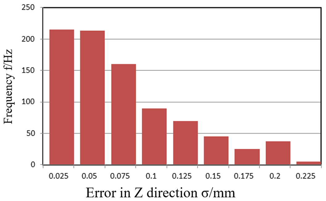
Figure 5Frequency histogram of position error on working point in (0, 100, 1000) by matrix method.
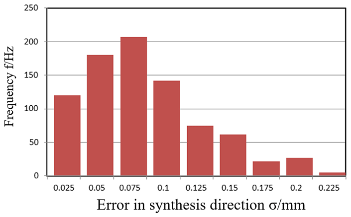
Figure 6Frequency histogram of position error on working point in (100, 100, 1000) by matrix method.
3.2 The simulation analysis for the error of the joint clearance by error independent method
The error independent action method is used in this analysis, and the parameters of each component of the parallel mechanism can be selected from the following parameters: c=400 mm, R=650 mm, r=250 mm. Suppose the clearance between Hooke's hinges is δu=0.08 mm, included angle αu in the range of (0,2π)and Obey the uniform distribution. Based on the error model of D-H matrix method, the error model is established by the method of matrix, and the error of output position error is simulated by Monte Carlo method. As shown in following Figs. 7–10, the sample size is 800, the error of the joint clearance of the mechanism based on the error independent action method is simulated in the XYZ three direction error and mechanism synthesis error.
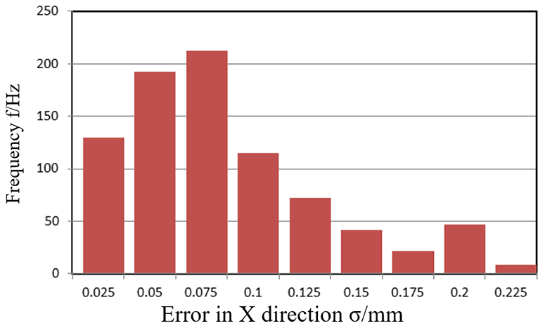
Figure 7Frequency histogram of position error on working point in (0, 0, 1000) by error independent method.
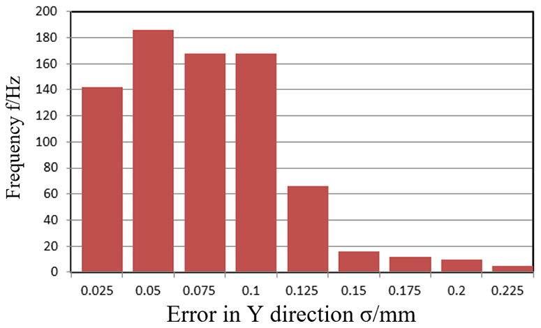
Figure 8Frequency histogram of position error on working point in (100, 0, 1000) by error independent method.
It can be noticed from Figs. 7 to 10 that when input error satisfy uniform distribution, the output end position error in the X, Y, Z direction caused by Hooke joint clearance error all meet the normal distribution. Table 2 lists the statistical parameters of the influence in the different positions of the position errors by error independent method.
Through the analysis of the data in Table 1 in the chart, the error can be obtained that the effects of joint clearance error of the moving platform in Z direction are lower than the other two directions.
Table 2Statistical parameters of the influence in the different positions of the position errors by error independent method.
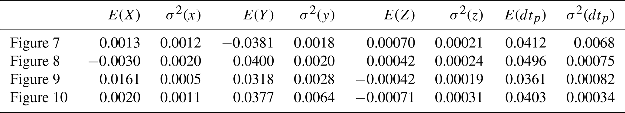
The platform position error is one order of magnitude smaller than the input, it is one in ten or one in fifth of input error. It can be obtained that 3-TPT Parallel mechanism can effectively avoid error cumulative of each joint and can offset a portion of input error through the action of each member and reaches the higher position accuracy.
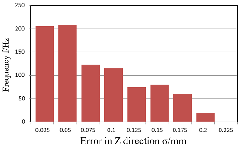
Figure 9Frequency histogram of position error on working point in (0, 100, 1000) by error independent method.
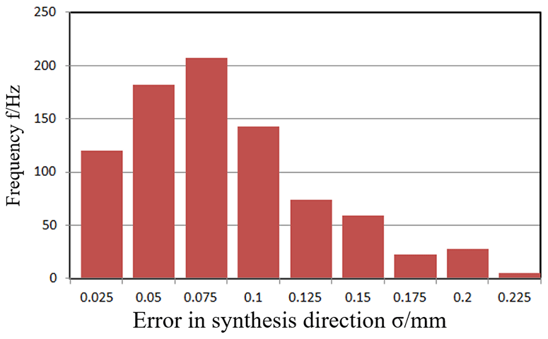
Figure 10Frequency histogram of position error on working point in (100, 100, 1000) by error independent method.
4.1 Attitude error modeling of parallel mechanism
In the ideal state, due to the constraint of the 3-TPT mechanism, the moving platform should be parallel to the base platform. But in fact, the mechanism is often unable to reach the ideal posture due to the existence of the mechanism error, the rod length error and clearance error. At this time the position of the moving platform will be affected by the deviation of its attitude and work position error. Because the effect of different positions of the various error sources on the mechanism error is also different. So the effect moving platform on different location should be considered when analyzing accuracy of the mechanism.
In the fixed coordinate system, The coordinates of the hinge point Bi of the base platform are in the fixed coordinate system. And the coordinates of the hinge points Pi of the moving platform in the fixed coordinate system are . Where i=1, 2, 3, there are three bars in parallel mechanism under arbitrary attitude to meet the condition equation.
Suppose that the length of the driving rod of the parallel mechanism is kept constant, and the coordinate of the three hinge points in the fixed coordinate system is when the moving platform is in an arbitrary attitude. Then each hinge point of moving platform still meet the driving rod length constraint conditions, then the equation is expressed as follows:
Where, the (rpxi rpyi rpzi) is the rotation increment of the coordinates of each hinge point of the moving platform, and the differential coefficient of Eq. (33) is given:
Where,
Where, are the coordinate changing values of the hinge point coordinates respectively due to the differential rotation of the moving platform. (Δxp Δyp Δzp) are the change value of center position of the moving platform respectively caused by the differential rotation of the moving platform. Prior to the differential rotation of the moving platform, the moving platform and the fixed platform can be considered to be in an ideal position. Then , put this into above equation, it is given as follows:
set to the coordinates of the hinge point of the moving platform in the coordinate system of the moving platform, and the (ξx ξy ξz) is the differential rotation of the moving platform around the three coordinate axes. Then,
Where,
From Eqs. (36) and (37), the error of the center of moving platform caused by differential rotation of the moving platform is given as follows,
Where,
Differential rotation of the moving platform is (ξx ξy ξz) that represents the attitude error of the moving platform. Equation (38) is the relationship between the posture errors of the moving platform, which can be used to establish the error mathematical model for further analysis.
4.2 Simulation of the influence of attitude error on the position error of mechanism
According to the Eq. (38), the position error of the mechanism moving platform can be calculated by the attitude error of the moving platform, and the design parameters of the system are r=250 mm, c=400 mm, and then Eq. (38) can be written as:
In the 3-TPT mechanism, Due to the length error of the driving rod, the gap error and the uneven temperature, the posture error may be caused by the attitude error of the mechanism moving platform, and the attitude error is not a stable value. The attitude error of the moving platform is ξ which is in line with the normal distribution, and set the values are σ=0.000284 μ=0.00104. According to the structure characteristic of 3-TPT mechanism, the connection between drive rod and each platform are Hooke joint, hence the value of rotation of the branch rod around its own axis is very small, that makes rotation error of moving platform around the Z axis is also very small, assume that ξz is one in ten of ξx and ξy. The simulation model is established with the above data and formula to check the results.
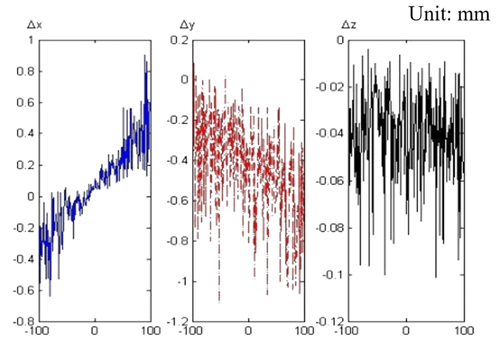
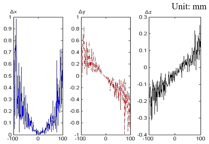
It is noticed from the above analysis that the position error in the three directions and the position relation is relatively independent. The distribution of the position error Δx Δy Δz in three directions is compared by simulating in a working condition. The position error caused by the attitude error while the moving platform moving from −100 to 100 in Y-axis direction when x=0 and z=1000 mm, as shown in Fig. 11. the Position error caused by the attitude error when y=0, z=1000 mm and , as shown in Fig. 12.
By comparing the results of the distribution of (Δx Δy Δz) in Figs. 11 and 12, It can be seen that the maximum value of Δx and Δy can reach 0.977 and 1.514 mm in the simulation range, while Δz is only 0.304 mm. The fluctuation of Δz is small in the simulation range. Hence, The visible posture error has great influence on the Δx and Δy errors of the position of the moving platform, and has less influence on the Δz. The influence of Δx and Δy on the accuracy of the mechanism should be researched in the process of product design.
Considering the influence of the attitude error of the moving platform on position error in three directions, the position error (Δx Δy Δz) of the center point of the moving platform along the XYZ axis is unified into a comprehensive evaluation index for modeling. Then the influence of attitude error on the position error in the center of the moving platform is simulated when z=1000 mm and z=800 mm, and the results are shown as follows Figs. 13 and 14.


By observing and comparing Figs. 13 and 14, the value of dv in the center of the plane center is very small, and with moving away from the center point, the error increases. The position error caused by the platform attitude error is smaller when the center is near the center point, and the error increases with moving away from the center point. And compared the value dv along the x, y two axis, you can find that dv along the x axis changes relatively large with the change of x, and it is smaller along the y axis with the change in y direction, and it is more larger and more far away from the center. Therefore, it should try to keep the working area at the center of the plane when designing the mechanism.
Parallel mechanism system is a multi-closed-loop, multi-branch error coupling structural system. The Accuracy of parallel mechanism is an important part for researching and designing of parallel mechanism. Due to the parallel mechanism requires flexible movement in its workspace, there must be some clearance between its adjacent joints to ensure the normal operation of the mechanism. The existence of joint clearance reduces the actual working accuracy of parallel mechanism to a great extent, which affects the working accuracy and performance of the mechanism. The influence of clearance on the accuracy of parallel mechanism can not be ignored, and this will become an important part of error analysis of parallel mechanism. Compared with the traditional series mechanism, the research methods of its accuracy characteristics are much more complex. Considering the system attitude error of hinge clearance, in this paper the error model of the working accuracy of parallel mechanism was established. The hinge clearance error of mechanism was differentiated by using D-H matrix method and error independent action method under the ideal state based on the obtained mechanism inverse solution equations, then the influence of clearance error on moving platform positioning error model was deduced for further accuracy analysis and mechanism design. The major findings are summarized as follows:
When the distance increases between moving platform and fixed platform, the position error of parallel mechanism become bigger and effect of Hooke joint clearance error on position error is more obvious.
The joint clearance errors on the combined effects of the moving platform with two methods are respectively and . It is shown that terminal position error of parallel mechanism is an order of magnitude smaller than input error, about one in ten or one in fifth of input error.
It can be noticed from simulation results that the effect of position errors on overall accuracy of 3-TPT parallel mechanism is significantly small near working plane center, and with the X axis location changing, it has little effect on accuracy, and with the Y axis location changing, the effect become bigger. The influence law was obtained from the above analysis is of great significance for the design and analysis of the parallel mechanism.
All data included in this study are available upon request by contact with the corresponding author.
CZ has made substantial contributions to the conception and design of the work, the acquisition, analysis and the interpretation of data for the work. And she hasdrafted the work or revised it critically for important intellectual content. ZZ has made a contribution to the acquisition of simulation experimental data and data collation.
The authors declare that they have no conflict of interest.
This work was supported by the Project of Promoting Talents in Liaoning Province (Grant No. XLYC1807065) and Shenyang Young and Middle-aged Science and Technology Innovation Talents Support Plan (Grant No. RC180193).
This research has been supported by the National Natural Science Foundation of China (grant no. 51575365) and the Natural Scientific Foundation of Liaoning Province (grant no. 2015020127).
This paper was edited by Doina Pisla and reviewed by two anonymous referees.
Akhadkar, N., Acary, V., and Brogliato, B.: 3D Revolute Joint with Clearance in Multibody Systems, in: Computational Kinematics, edited by: Zeghloul, S., Romdhane, L., and Laribi, M., Mechanisms and Machine Science, Vol 50. Springer, Cham, 2018a.
Akhadkar, N., Acary, V., and Brogliato, B.: Multibody systems with 3D revolute joints with clearances: an industrial case study with an experimental validation, Multibody Syst. Dyn., 42, 249–282, https://doi.org/10.1007/s11044-017-9584-5, 2018b.
Amir, R. and Alireza, A.: Study on Jacobian, singularity and kinematics sensitivity of the FUM 3-PSP parallel manipu-lator, Mech. Mach. Theory, 86, 211–234, https://doi.org/10.1016/j.mechmachtheory.2014.11.009, 2015.
Cavalieri, F. J. and Cardona, A.: Non-smooth model of a frictionless and dry three-dimensional revolute joint with clearance for multibody system dynamics, Mech. Mach. Theory, 121, 335–354, https://doi.org/10.1016/j.mechmachtheory.2017.09.018, 2018.
Dai, Y., Fu, Y., Li, B., and Wang, W.: Clearance effected accuracy and error sensitivity analysis: A new nonlinear equivalent method for spatial parallel robot, J. Mech. Sci. Technol., 31, 5493–5504, https://doi.org/10.1007/s12206-017-1044-x, 2017.
Hiwa, G. and Gholamhasan, P.: Kinematic design of a novel 4-DOF parallel parallel mechanism for turbine blade machining, Int. J. Adv. Manuf. Tech., 74, 729–739, https://doi.org/10.1007/s00170-014-6015-0, 2014.
Huang, P., Wang, J., Wang, L., and Yao, R.: Identification of structure errors of 3-PRS-XY mechanism with Regularization method, Mech. Mach. Theory, 46, 927–944, https://doi.org/10.1016/j.mechmachtheory.2011.02.006, 2011.
Liang, M. I., Yin, G. F., Sun, M. N., and Wang, X. H.: Effects of preloads on joints on dynamic stiffness of a whole machine tool structure, J. Mech. Sci. Technol., 26, 495–508, https://doi.org/10.1007/s12206-011-1033-4, 2012.
Mihai, D. and David, G.: Dynamic analysis of a flexible linkage mechanism with cracks and clearance, Mech. Mach. Theory, 45, 1909–1923, https://doi.org/10.1016/j.mechmachtheory.2010.07.006, 2010.
Mikhael, T., Stéphane, C., and Alexandre, G.: Sensitivity analysis of parallel manipulators using an interval lineariza-tion method, Mech. Mach. Theory, 25, 93–114, https://doi.org/10.1016/j.mechmachtheory.2013.09.004, 2014.
Piras, G., Cleghorn, W. L., and Mills, J. K.: Dynamic finite-element analysis of a planar high-speed, high-precision parallel manipulator with flexible links, Mech. Mach. Theory, 40, 849–862, https://doi.org/10.1016/j.mechmachtheory.2004.12.007, 2005.
Singhee, A. and Rutenbar, R. A.: Why quasi-Monte Carlo is better than Monte Carlo or Latin hypercube sampling for statistical circuit analysis, IEEE T. Comput. Aid. D., 26, 1763–1776, https://doi.org/10.1109/TCAD.2010.2062750, 2010.
Subudhi, B. and Morris, A. S.: Dynamic modeling, simulation and control of a manipulator with flexible links and joints, Robot. Auton. Syst., 41, 257–270, https://doi.org/10.1016/s0921-8890(02)00295-6, 2002.
Wu, J., Wang, L. P., and Guan, L. W.: A study on the effect of structure parameters on the dynamic characteristics of a PRRRP parallel manipulator, Nonlinear Dynam., 74, 227–235, https://doi.org/10.1007/s11071-013-0960-2, 2013.
Yan, S., Xiang, W., and Zhang, L.: A comprehensive model for 3D revolute joints with clearances in mechanical systems, Nonlinear Dynam., 80, 309–328, https://doi.org/10.1007/s11071-014-1870-7, 2015.
Zaeh, M. and Siedl, D.: A new method for simulation of machining performance by integrating finite element and mul-ti-body simulation for machine tools, Proc. CIRP, 56, 383–386, https://doi.org/10.1016/j.cirp.2007.05.089, 2007.
Zhang, L. J. and Li, Y. Q.: Error analysis of spherical 2-dof parallel manipulator with actuation redundancy, Chin. J. Mech. Eng.-En., 49, 148–154, https://doi.org/10.3901/JME.2013.07.148, 2013.
Zheng, E., Zhu, R., Zhu, S., and Lu, X.: A study on dynamics of flexible multi-link mechanism including joints with clearance and lubrication for ultra-precision presses, Nonlinear Dynam., 83, 137–159, https://doi.org/10.1007/s11071-015-2315-7, 2016.
Zhu, C. X., Katupitiya, J., and Wang, J.: Effect of links deformation on motion accuracy of parallel manipulator based on flexible dynamics, Ind. Robot., 44, 776–787, https://doi.org/10.1108/IR-12-2016-0368, 2017.
- Abstract
- Introduction
- The error model of parallel mechanism with joint clearance
- Simulation of joint clearance error effect on the accuracy of 3-TPT parallel mechanism
- Analysis of the position error of the moving platform caused by the attitude error of the parallel mechanism
- Conclusion
- Data availability
- Author contributions
- Competing interests
- Acknowledgements
- Financial support
- Review statement
- References