the Creative Commons Attribution 4.0 License.
the Creative Commons Attribution 4.0 License.
 | 07 Jun 2019
Numerical analysis of the influence of the damping rings' thickness on interrupted dynamic tension results using SiC-reinforced ZC71 magnesium alloy specimens
Roberto-Alonso González-Lezcano
José-Manuel del Río Campos
This article discusses the influence of the thickness of the damping rings used for interrupting a dynamic tension experiments on the results of a modified split Hopkinson tension bar (SHTB). In this paper a device enclosed in an external fixture used for interrupting a dynamic tension experiment in a SHTB is studied. The novelty of this manuscript with respect to previous studies lies in the fact that the dynamic tension experiment in a SHTB is interrupted in order to study the mechanical behavior of the material at high strain rates. The role played by such device is to interrupt the experiment at different levels of plastic deformation, particularly when the specimen is about to reach its failure strength. Finite-element (FE) simulations of high-strain-rate tension experiments are accomplished on a particle-reinforced metal matrix composite specimen (namely SiC-reinforced ZC71 magnesium alloy) when varying the thickness of the damping rings. Interrupting the test before the specimen breaks offers the possibility of being able to study in a more detailed way the deformation process of such material at high strain rates. Therefore, this work focuses on the study of the behaviour of materials undergoing high strain rates, developing a tool which allows materials to withstand different levels of strain rates in a controlled manner and providing guidance for future studies. In view of this research, it can be concluded that the thickness of the damping rings is a factor that can resolutely influence the interrupted dynamic tension experiment results avoiding the specimen's failure by optimally buffering the experiment using 0.8 mm thick lead damping rings.


The emergence of metallic matrix composites (MMCs) has been one of the major innovations in materials during the last 30 years, since they combine an excellent mechanical behaviour with a light weight. These materials consist of a metallic matrix such as aluminum-based and magnesium-based alloys, among other metals, and a reinforcement of fibers or particles, which are generally made of ceramic materials. The matrix provides the structural element and transmits the stresses to the reinforcement, which undergoes the stresses transmitted by the matrix (Whitehouse and Clyne, 1993; Lloyd, 1994). Therefore, in terms of the shape of the reinforcement, an initial classification for these materials can be established, i.e., fiber-reinforced MMCs (FMMCs) and particle-reinforced MMCs (PMMCs).
This article shows both analytically and experimentally the use of an interruption mechanism based on the use of a damping element made of lead enclosed within an interruption fixture inside a modified split Hopkinson tension bar which can absorb the impact energy by deforming plastically. It also allows to interrupt the dynamic experiment in order to study the behaviour of the particle-reinforced composite specimen. Although different tests on metallic alloys at different strain-rate levels have already been reported, such as selected aluminium alloys (Oosterkamp et al., 1999; Reyes et al., 2006), wrought iron (El-Magd and Abouridouane, 2006), and other alloys (Smerd et al., 2005; Field et al., 2004; Yang et al., 2014) such as copper (Dongfang et al., 2010; Böhme, 1988) and including composites (del Río et al., 2005; Hamouda and Hashmi, 1998; Harding and Welsh, 1983) and polymers (Khlif et al., 2012), such as polystyrene, there are still much to be said about the behaviour of MMCs at high strain rates.
The split Hopkinson tension bar (SHTB) is the most widespread method for material characterization at high strain rates. Research on tensile and compressive high strain-rate testing has been developed (Lindholm and Yeakley, 1968) as well as the wave-propagation effects in dynamic loading (Albertini and Montagnani, 1976). Although different authors have been testing materials at high-strain rates (Nicholas, 1981; Staab and Gilat, 1990), and experimental research of the deformation of Hopkinson bar specimens have been accomplished (Thakur et al., 1996; Verleysen and Degrieck, 2004), the novelty of this research with respect to previous studies lies in the fact that the dynamic tension experiment in a SHTB is interrupted in order to study the mechanical behavior of the material at high strain rates. Other studies have been modifying the classic Hopkinson bar testing (Gray et al., 2000; Swantek et al., 2001) as well as designing new split Hopkinson tensile bars (Gerlach et al., 2012). Material properties can therefore be obtained at strain rates in the range between 200 and 1500 s−1 as per a standardized experiment (ASTM E8, 2013).
The SHTB consists of two cylindrical bars of different lengths called the incident and the transmission bar respectively, between which a specimen of the material being tested is sandwiched. Cylindrical bars facilitate the study of the wave propagation as well as the optimization of their adequate dimensions in order to accomplish the experiment.
The bars must have a sufficiently high yield strength, so that the test can hardly affect them. Their mechanical properties must be accurately determined, since the results strongly depend on such precision. The bars are supported by two movable supports, which in turn can be adjusted on guides fixed to a bench, so as to ensure the perfect alignment of all the components.
Two strain gauges mounted on the incident and transmission bars enable the stress waves to be measured as clearly as possible. The information gathered by the strain gauges is then forwarded to a data acquisition system that consists of a signal conditioner and an oscilloscope, where test data can be recorded and computed.
During the tension experiment at high strain rates, the specimen ends are screwed into both the incident and transmission bars. The steel projectile impacts the incident bar, which is longer than the transmission bar. The hollow cylindrical projectile is launched with a maximum pressure of 8 bar from a cannon impulsed by a compressed air chamber. The projectile generates compression waves which are converted to tensile waves by a flange. The optimum pressure can be selected in every particular test by using a control valve. The impact speed of the projectile can be adjusted and therefore the strain rate can be varied.
The stress pulse travels through the bars and then it is recorded to obtain the stress–strain curve. The conclusions about the specimen's behaviour are drawn using the 1-D stress wave propagation theory (Gama et al., 2004). The results of the incident, reflected, and transmitted waves can be recorded by means of strain gauges mounted on both bars (Richter et al., 2016; Kolsky, 1949; Achenbach, 1973; Resnyansky, 2000).
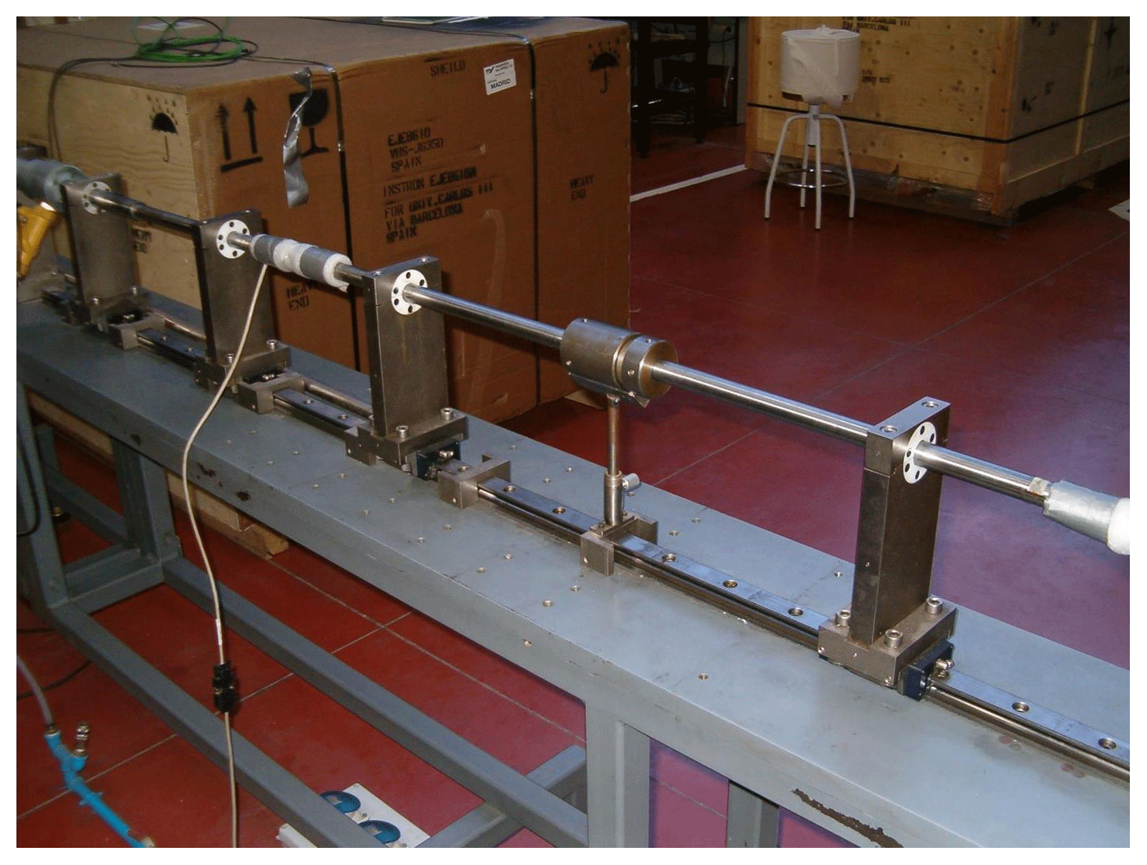
A modified SHTB on which an external interruption fixture is mounted on the bars was developed by González-Lezcano et al. (2003) was installed in the Universidad Carlos III de Madrid Engineering Laboratory.
Many researches have been accomplished on the SHTB apparatus, particularly with regard to its interruption (Essa et al., 2007). The purpose of interrupting a dynamic experiment is to achieve a predefined strain on the material (and hence on the specimen) without altering the strain rate reached. Once the experiment has been interrupted, the damage caused to the material can be estimated. If the material is a particle-reinforced composite, such estimation can be carried out by counting the broken or decohesionated particles. The final strain can be finally associated with the damage produced for a certain strain rate.
The interruption mechanism is based on the use of two damping rings working as buffers which are enclosed in an external interruption fixture. They can absorb the impact energy by deforming plastically and therefore allowing a tensile stress distribution in the specimen. Otherwise, the specimen would receive an undesired compressive stress wave.
The interruption fixture will play the role of an ideal rigid body, which will not allow the damping rings to expand, so that the rings have to deform in order for the cylinder to deform as well. The element is given a great robustness in its dimensions after manufacturing it thick enough and using a material with excellent mechanical properties. Therefore, the wave hardly provokes its deformation. The interruption fixture will actually maintain a certain length between the rings, causing them to interrupt the experiment. The design of the interruption fixture allows to place the rings inside it, and therefore it is necessary to fabricate a separate model with two threaded pieces. Its dimensions give great robustness to the system and provides the possibility to work with rings of different dimensions. The thread, apart from giving a good solidity to the entire device, provides a wide possibility of adjustment to the different rings to be studied.
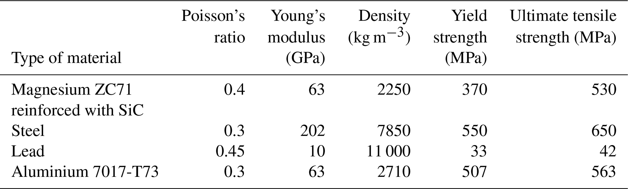
Table 1Properties of the ZC71 magnesium alloy reinforced with SiC compared with steel, lead, and aluminium 7017-T73.
The interruption fixture dimensions are bigger than the enlargement of the bars to avoid friction with them. The validity of such interruption fixture shall be based on its rigidity, which must not allow its initial length to be varied. The role of the interruption fixture is to interrupt the tension experiment at different levels of plastic deformation, particularly before the specimen reaches its failure strength. The specimen tested at a given strain rate and at a given deformation level can be studied microscopically in a laboratory. Interrupting the experiment before the specimen reaches its failure strength offers the possibility of being able to study in a more detailed way the deformation process at high strain rates as well as the influence of the variations of the geometry of the specimen in the results (Verleysen et al., 2009).
Therefore, this research focuses on the study of the behaviour of materials undergoing high strain rates, developing a tool which allows materials to withstand different levels of strain rates in a controlled manner. After a series of numerical simulations, the impact limit is obtained, which corresponds to a value equal to −5000 mm s−1.
The system developed in 2003 included damping rings to attenuate the effects of the compressive waves produced as a result of including the external interruption fixture. In such modified SHTB apparatus, the bars were designed with a non-uniform cross section. Moreover, an increment in the cross-sectional area of the bar ends which are in contact with the specimen was necessary to properly mount the external interruption fixture in parallel with the bars. Such increment in the cross-sectional area of the above-mentioned bar ends does not significantly interfere with the classical SHTB apparatus behaviour.
The dimensions of the bars used are summarized in Table 1. The steel bars are made in one piece in order to provide the minimum resistance to the wave passage. They are provided with the appropriate lengths to optimize the test. Table 1 shows the mechanical properties of aluminum 7017-T73 alloy at high strain rates as per previous studies (Pérez-Martín et al., 2014).
The properties of ZC71 magnesium alloy (Mg-6.5Zn-1.2 Cu-0.5 Mn) when reinforced with 12 % of SiC particles are also shown in Table 1 compared to those of other materials. The reinforcement of SiC modifies the deformational behaviour of the Magnesium alloy.
The damping rings are made of lead. As for the FE analysis, other materials have been simulated besides lead in order to study the influence of the damping rings material on the interruption process. Thus, different compositions of glass fibre-reinforced polystyrene (GF-polystyrene) were used to find the influence of the damping rings density on the specimen strain.
The material to be tested is a SiC-reinforced ZC71 magnesium alloy. The properties to be introduced in ABAQUS were collected from the stress-strain curve obtained from other SHTB experiments accomplished on SiC-reinforced ZC71 magnesium at 600 s−1 (Essa and Pérez, 2003; Essa et al., 2003).
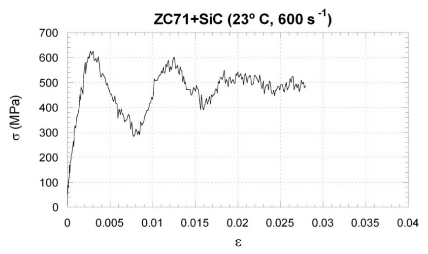
Figure 1Stress-strain curve pertinent to SiC-reinforced ZC71 magnesium alloy at a strain rate equal to 600 s−1.
The aspect of the stress-strain curve shown in Fig. 1 is due to the fact that the experiment is carried out at high strain rates. It should be noted that the strain rate obtained through the simulation is lower than that of the curve from which the properties of the material were taken, but the approximation is more accurate than the properties pertaining to the quasi-static test. The study of stresses in the SHTB is accomplished when using SiC-reinforced ZC71 magnesium alloy at −5000 mm s−1.
Many metallic materials show in their mechanical behaviour a significant dependence to the strain rate. The behaviour of a material subject to variable loads over time presents two important differences in relation to its behaviour under static conditions. First, due to the participation of the inertia forces in the equilibrium, and secondly due to the possible influence of the strain rate on the properties of the material. In general, an increase in the strain rate values results in an increase of the yield strength and the tensile strength values.
This fact implies negative effects such as the reduction of the tensile strength of PMMCs and the precipitation of their fracture. From 1961 it was begun to consider that the materials in use (mainly aluminum) increased their sensitivity to the strain rate when it was higher than 1000 s−1. From the viewpoint of solid mechanics, such increase of the sensitivity can be attributed to inertia effects. However, from a physical viewpoint, the sensitivity to the strain rate is attributable to the abrupt transition from a thermal behaviour to a viscous behaviour.
The behavioral complexity of such materials, coupled with their recent origin, has caused that most researchers in the past had focused on their behaviour at low strain rates. Thus, for example, the effect of the fracture of Al2O3 or SiC particles within an aluminum alloy at low strain rates exhibit a brittle behaviour as the particles are progressively broken during their plastic deformation period, being the probability of its fracture bigger as the size of the reinforcement increases.
The stress-strain curves at high strain rates are generally obtained by accomplishing experiments using the Hopkinson bar. The results obtained when using SiC-reinforced aluminum alloy are detailed herein: its apparent modulus of elasticity and yield strength do not practically vary for strain rates between 10−3 and 150 s−1, but they increase from this value onwards. The failure strain increases with the strain rate, which contrasts with the behaviour of other materials in which such strain decreases when the strain rate gets raised.
Essa and Pérez (2003) analyzed the ZC71 alloy and the same reinforced alloy under conditions of tensile and compressive loads. As per their research, for a given strain level the corresponding stress in a experiment at high strain rates is always higher than under quasi-static conditions. In tensile tests, an increase in the strain rate has a greater effect on the mechanical response of the reinforced material than that of the base alloy. This tendency is not so clear in compression experiments. The effect of temperature under quasi-static conditions is more significant than that of dynamic experiments.
The analysis of such curves as shown in Fig. 2 shows that their plastic branches are substantially parallel indicating that the mechanisms of strain hardening are independent of the strain rate.
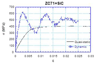
Figure 2Stress-strain curve pertinent to SiC-reinforced ZC71 magnesium alloy at high strain rates.
The finite-element (FE) method is a powerful technique originally developed for numerical solution of complex problems in structural mechanics. In this article, the FE simulations are performed using the FE software ABAQUS (from ABAQUS, Inc.). The FE models described herein are created with ABAQUS/CAE. ABAQUS/Explicit code is used for the calculations to study the precise dynamical phenomena in the specimen. Instances are meshed using quadrilateral elements (CAX4R) and a structured meshing. In general, structured meshing provides the most control over the mesh that ABAQUS/CAE generates. ABAQUS/CAE respects seed distribution wherever possible when generating a structured mesh. For modeling, a strain-rate sensitive model is employed. The model is complemented by assuming that the transverse stresses are zero. A 1-D code is developed on the basis of the Godunov scheme (Godunov and Romenskii, 2003).
Three FE models are established. A classical SHTB model without the external interruption fixture (Model 1), a modified SHTB model increasing the cross-sectional area of the bar ends which are in contact with the specimen but without the external interruption fixture (Model 2), and a modified SHTB model with the entire interruption device including the fixture and the damping rings enclosed within (Model 3). Finite-element simulations of high-strain-rate tension experiments have been performed on SiC-reinforced ZC71 magnesium alloy specimens using different dimensions of the damping rings made of lead at different strain rate levels in order to reproduce the same stress wave observed in experiments accomplished with SHTB apparatus. The above-mentioned FE models have already been validated by previous studies made by the authors of this article (González-Lezcano and del Río, 2015a, b) and are described more deeply therein. The modeling results correlate well with the SHTB experimental results, confirming the validity of the FE models.

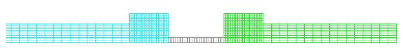

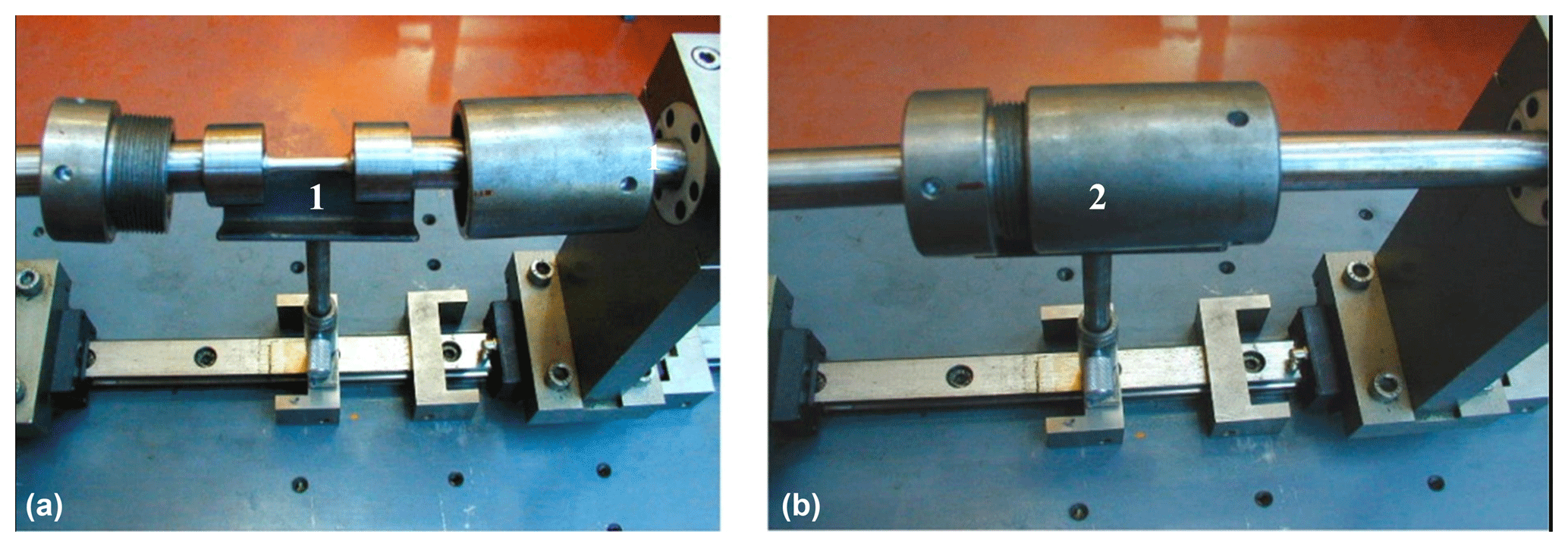
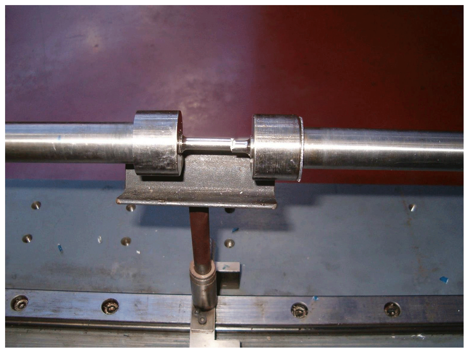
Figure 6External interruption fixture when (a) unscrewed to insert the damping rings or access the specimen and (b) when screwed. Legend: (1) Specimen; (2) Interruption device.
After such research, these authors then concluded that the thickness of the damping rings is a factor that can resolutely influence the interrupted dynamic tension experiment results, while their cross-sectional area can be excluded as a factor influencing the results of the modified SHTB experiments. Experiments using aluminum 7017-T73 alloy specimens and lead damping rings whose thickness ranged from 2 to 6 mm values were considered therein (González-Lezcano and del Río, 2017).
Details of FE meshes of the three models for validating interrupted mechanisms can be found below: the classical SHTB model without interruption (Model-1 shown in Fig. 3), the modified SHTB model when increasing the bar ends without assembling the interruption device (Model-2 shown in Fig. 4), and the modified SHTB model with the entire interruption mechanism (Model-3 shown in Fig. 5).
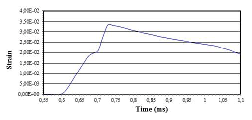
Figure 7Strain-time curve in the centre of the specimen when using SiC-reinforced ZC71 magnesium alloy at −5000 mm s−1.
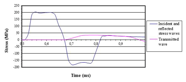
Figure 8Incident and reflected stress waves pertinent to the modified SHTB (Model 2) when using SiC-reinforced ZC71 magnesium alloy at −5000 mm s−1.
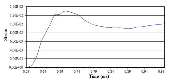
Figure 9Strain-time curve in the centre of the SiC-reinforced ZC71 magnesium alloy specimen for modified SHTB (Model 3) when using 1 mm thick lead damping rings at −5000 mm s−1.
The interruption fixture performs as an actual rigid body avoiding the expansion of the damping rings. Therefore, the damping rings deform when the specimen deforms. This can be achieved fabricating a robust element with the suitable mechanical properties and whose dimensions are consistent with the aim pursued. The interruption fixture maintains a constant length between the damping rings allowing them to stop the experiment. The elongation of the test specimen can therefore be controlled by the length of the external interruption fixture. The element is manufactured in two threaded pieces to permit an easy access to the specimen. The damping rings can be suitaby adjusted by means of the threaded pieces. Figure 6 shows a picture of the two-piece external interruption fixture when (panel a) unscrewed to insert the damping rings or access the specimen and when (panel b) screwed.
The numerical technique produces clear limits on strain, which are achieved using the following formula:
where
-
ε0=0.028
-
L0=30 mm
-
-
T= thickness of the lead damping rings
Regarding the thickness of the lead damping rings, the following maximum value is obtained after replacing such values:
From the above, different values of the ring's thickness have been selected. Such values range from 0.5 mm up to 1 mm, since there will be an added factor caused by the dimensions of the gap between the evolvent and the bars, which increases the maximum thickness.
Numerical simulations on both classical SHTB model (Model 1) and modified SHTB models (Models 2 and 3) are accomplished. Figure 3 shows the strain-time curve obtained in the centre of the SiC-reinforced ZC71 magnesium alloy specimen at −5000 mm s−1.
It can be observed that the failure elongation value (0.028 µm) is exceeded, and strain values up to 0.032 µm are eventually reached.
The following figures show the waves in every bar.
Figure 8 shows the incident wave peak, which reaches 204 MPa. Therefore, impacts that reach or even surpass such incident wave must be accomplished in order to test the buffering capacity of the interruption device. Moreover, it can be observed that the reflected compression wave is lower than the incident one, as expected, since a transmission wave appears as a result of such difference. Next, the strain-time curve obtained in the centre of the SiC-reinforced ZC71 magnesium alloy specimen for modified SHTB (Model 3) when using 1 mm thick lead damping rings at −5000 mm s−1 is represented.
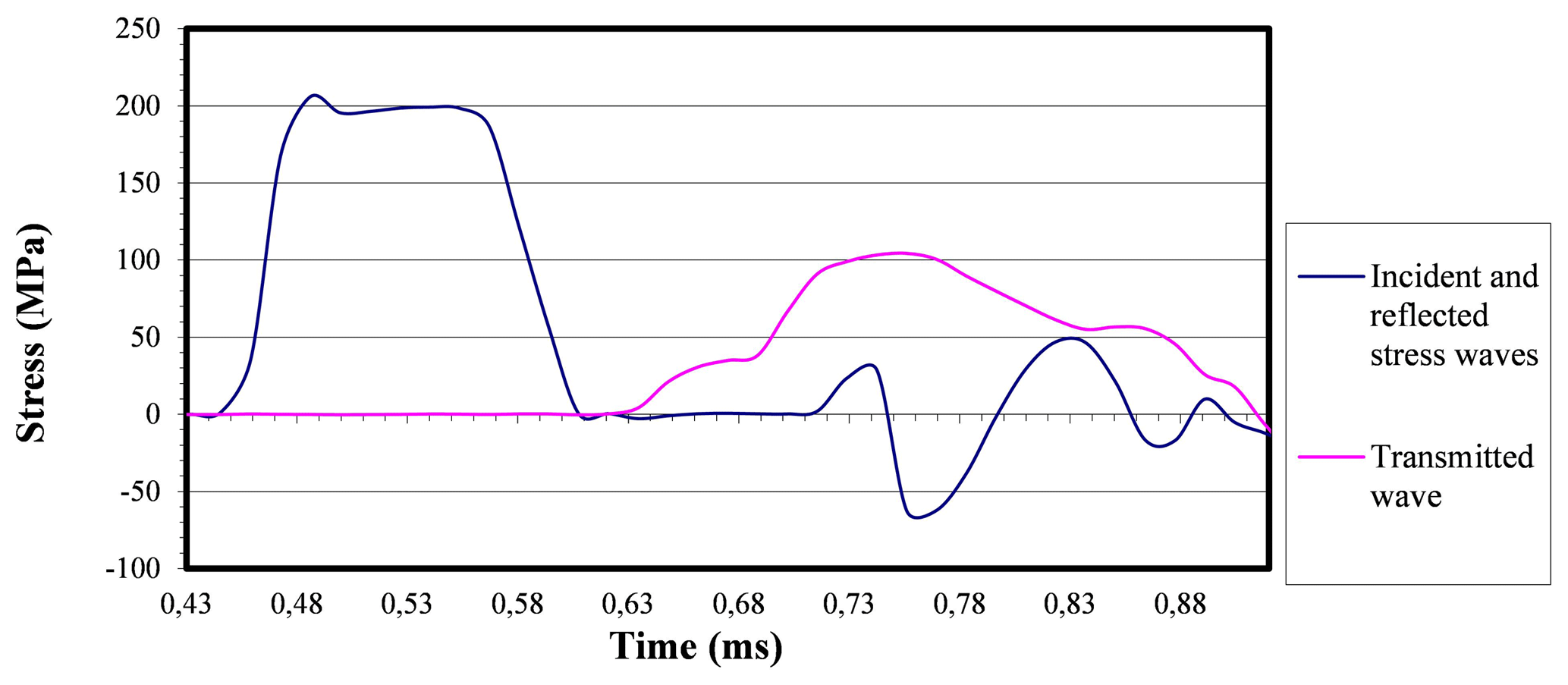
Figure 10Incident and reflected stress-time curves in the centre of the SiC-reinforced ZC71 magnesium alloy specimen pertinent to the modified SHTB (Model 3) when using 0.5 mm thick lead damping rings at −5000 mm s−1.

Figure 11Incident and reflected stress-time curves in the centre of the SiC-reinforced ZC71 magnesium alloy specimen pertinent to both modified SHTB (Model 2) and modified SHTB (Model 3) when using 0.5 mm thick lead damping rings at −5000 mm s−1.
Figure 9 shows the strong influence of the interruption device, which decreases elongation values from 0.032 to 0.13 µm. Thus, the experiment is interrupted, avoiding the fracture of the specimen.
The curves pertinent to the stress waves on the bars are shown here below.
A strong damping effect is observed as per Fig. 10 with a substantially diminished reflected wave and a transmitted wave which increases considerably at an inflection point in which the interruption device starts affecting the transmission bar performance. In this case, it is observed that the waves show significant discrepancies due to the presence of the interruption device, which partly absorbs the incident wave before it reaches the bar end. In the modified SHTB which includes the interruption device (Model 3), the transmitted wave travels through two different paths (i.e., the specimen and the interruption device), while in the modified SHTB without interruption device (Model 2), the transmitted wave only travels through the specimen. First the incident and reflected waves are analyzed.
Figure 11 clearly shows similar incident waves pertinent to both modified SHTB (Model 2) and modified SHTB (Model 3) but a great difference in reflected waves, which evidences the strong effect of the interruption device. The transmitted waves are shown herebelow (Fig. 12).
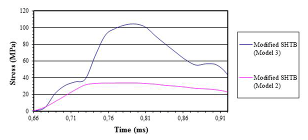
Figure 12Transmitted stress-time curves in the centre of the SiC-reinforced ZC71 magnesium alloy specimen pertinent to both modified SHTB (Model 2) and modified SHTB (Model 3) when using 0.5 mm thick lead damping rings at −5000 mm s−1.
Figure 12 shows that a similar initial behaviour can be observed in both modified SHTB (Model 2) and modified SHTB (Model 3) until the interrupting device interrupts the transmission bar causing the transmitted wave to increase considerably. After analyzing the behaviour of both arrangements when using SiC-reinforced ZC71 magnesium alloy as a test material, the behaviour of the test interruption device with more severe impacts leading to higher strain rates is to be analyzed. The impact selected was the one relevant to the lab experiments. Simulations on modified SHTB (Model 3) using specimens made of SiC-reinforced ZC71 magnesium alloy lead rings 1, 0.8, and 0.5 mm thick as a damping material at strain rates equal to −7000 mm s−1 are studied. The strain-time curve is displayed to realize whether the experiment gets interrupted when using 1 mm thick lead rings.
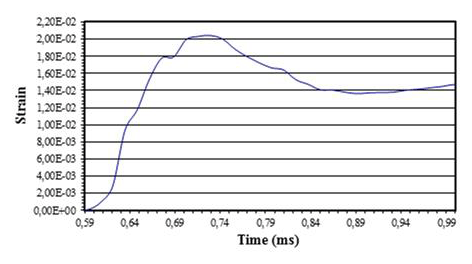
Figure 13Strain-time curve in the centre of the SiC-reinforced ZC71 magnesium alloy specimen pertinent to the modified SHTB including the interruption device (Model 3) when using 1 mm thick lead damping rings at −5000 mm s−1.
It is observed that the experiment gets interrupted after reaching an elongation value equal to 0.02 µm, lower than the one pertinent to the failure strength of the material, which corresponds to an elongation of 0.028 µm. Comparing this curve with that of Fig. 5 (when using 1 mm thick lead damping rings at −5000 mm s−1), a greater deformation can be noticed since in this case the impact is stronger. Figure 14 shows the strain-time curves when 0.8 mm thick lead damping rings are used.
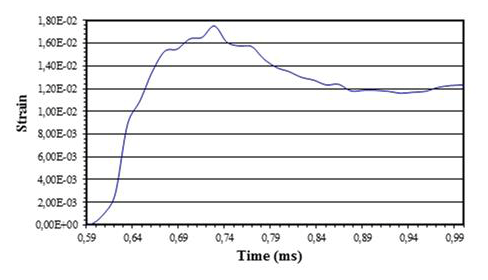
Figure 14Strain-time curve in the centre of the SiC-reinforced ZC71 magnesium alloy specimen pertinent to the modified SHTB including an interruption device (Model 3) when using 0.8 mm thick lead damping rings at −5000 mm s−1.
Figure 14 shows even lower deformations than those depicted in Fig. 13, which evidences that the lower the thickness of the damping rings, the lower the strain levels reached within the specimen, since the buffering effect results stronger. Figure 15 shows the results obtained when using 0.5 mm thick lead damping rings at −7000 mm s−1.
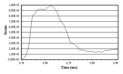
Figure 15Strain-time curve in the centre of the SiC-reinforced ZC71 magnesium alloy specimen pertinent to the modified SHTB including an interruption device (Model 3) when using 0.5 mm thick lead damping rings at −7000 mm s−1.
Figure 15 provides the lowest strain levels obtained in the specimen since the damping effect is the most severe of those studied. From this curve it is possible to appreciate a rapid decrease of the strain levels, which will be ascertained by the enormous compression wave that appears after such an important buffering effect.
In order to verify the validity of the results numerically obtained, the last three simulated cases were experimentally studied in the lab using the modified SHTB. The experiments were carried out in the Universidad Carlos III de Madrid Engineering laboratory using SiC-reinforced ZC71 magnesium alloy specimen and lead damping rings.
First, the projectile impact level is sought to provide adequate stress values in the specimen. The maximum stress of the incident wave is taken as the parameter which provides a measure of the extent of the impact.
The stress levels reached must be higher than the numerical simulations, so that the specimen can easily reach its failure strength.
The stress-strain curves of the material are obtained at a strain rate that depends on the impact of the projectile within the modified SHTB including the interruption fixture in which the damping rings with different values of their thickness are enclosed. The data obtained from the interrupted experimens after varying the thickness of the damping rings are compared with the numerical FE results.
In this experiment the pressure used is 3.5 bar, which provides a stress wave in the incident bar of approximately 290 MPa.
The maximum stress of 289 MPa obtained surpasses the numerical value (90 MPa). It should be noted that the purpose of this test is to study the behaviour of the materials undergoing high strain rates and therefore it would be advisable to work with impacts which provide the tested specimens with high strain rates. It must be taken into account that the oscilloscope begins to measure the signal at the moment when a piece of information arrives through the strain gauge, and therefore, there is a delay of the signal.
Once the pressure control pressure has been selected, the test is carried out on the modified SHTB (Model 2), i.e., without using the interruption device. As expected, the specimen reaches its failure strength. The stress-strain curve obtained is shown in Fig. 17.
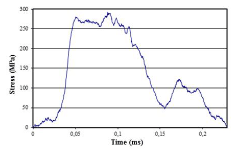
Figure 16Stress wave relating to the classical SHTB (Model 1) at a pressure equal to 3.5 bar.
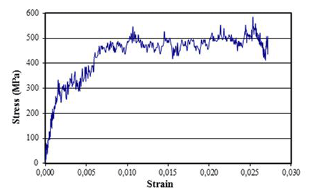
Figure 17Stress-strain curve relating to the modified SHTB without the interruption fixture (Model 2) at a pressure equal to 3.5 bar.
The stress-strain curve directly reflects the behaviour of the tested material. The 1-D stress wave propagation equation and uniaxial stress and strain relations cannot be applied in this case to obtain the stress-strain curves and therefore one or several strain gauges are mounted on the specimen itself. As a consequence of the above, the stress waves obtained in each bar are considered separately instead of associated in the form of a stress-strain curve. Therefore, the incident and reflected waves are plotted to analyze them separately when studying the modified SHTB.
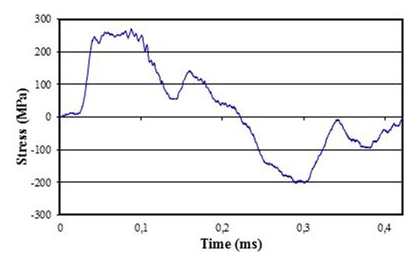
Figure 18Incident and reflected stress waves relating to the modified SHTB without the interruption fixture (Model 2) at a pressure equal to 3.5 bar.
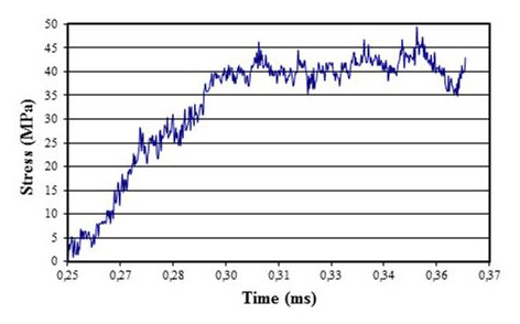
Figure 19Transmitted stress wave relating to the modified SHTB without the interruption fixture (Model 2) at a pressure equal to 3.5 bar.
A maximum stress value in the incident wave equal to 272 MPa and a minimum stress value in the reflected wave of −203 MPa can be found. Their addition is the value transmitted directly to the specimen and to the transmission bar. Next, the transmitted wave detected by the strain gauge on the transmission bar is shown.
Figure 19 shows the stress levels in the transmission bar until the specimen breaks.

Figure 20Stress wave relating to the modified SHTB without the interruption device (Model 2) at a pressure equal to 3.5 bar.
Figure 20 shows the stress wave until the specimen's failure.

Figure 21Strain rate to time curve relating to the modified SHTB without the interruption device (Model 2) at a pressure equal to 3.5 bar.
The strain rate reached during the experiment is around 370 s−1.
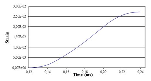
Figure 22Strain-time curve relating to the modified SHTB without the interruption device (Model 2) at a pressure equal to 3.5 bar.
A maximum elongation equal to 2.72 µm at a time ms is found, greater than the time relating to the maximum stress value, which is ms. This is due to the above-mentioned time delay undergone by the material at high strain rates.
After analyzing the modified SHTB without the interruption device (Model 2) at 3.5 bar, the same conditions are applied to the modified SHTB in which the experiment is interrupted (Model 3). A SiC-reinforced ZC71 magnesium alloy specimen, lead damping rings, and the same pressure level are used.
Before setting up the interrupting process, the damping rings are cut at a point on their cross-sectional area. Their malleability becomes an advantage to provide them with the appropriate shape and mount them inside the external fixture. Lead is an ideal material for this purpose due to its ease of handling and its malleability.
The rings are finally mounted in the concentric position to the bar. After screwing the casing, the experimental apparatus is ready to accomplish the experiment. The casing is perfectly screwed so that there is no gap and both rings are in direct contact with the bar surfaces. Therefore the casing must not tilt vertically during the experiment, and a support system must be placed to adjust it to the height of the casing. The experiment to be analyzed is accomplished at a pressure of 3.5 bar. The specimen is 6.1 mm long and 29.5 mm diameter. The damping ring is 1 mm thick and 4 mm wide.
The rings are finally mounted in the concentric position to the bar. After screwing the casing, the experimental apparatus is ready to accomplish the experiment.
He casing is perfectly screwed so that there is no gap and both rings are in direct contact with the bar surfaces. Therefore, the casing must not tilt vertically during the experiment, and a support system must be placed to adjust it to the height of the casing.
The experiment to be analyzed is accomplished at a pressure of 3.5 bar. The specimen is 6.1 mm long and 29.5 mm diameter. The damping ring is 1 mm thick and 4 mm wide.
It can be observed how the specimen breaks and the subsequent deformation found in the damping rings. The ring of the incident bar deforms too much. Figures 23 and 24 shows the rings and the specimen after the experiment.
The great deformation undergone by the ring placed on the incident bar can be observed. Figure 25 shows the incident and reflected waves obtained by the strain gauge located in the incident bar. The same time interval has been used in order to be able to contrast both experiments at any moment.
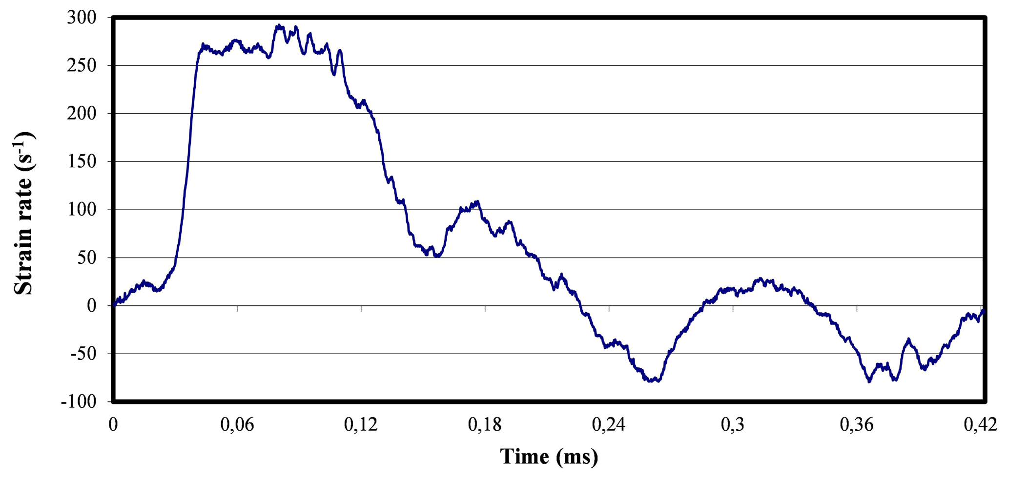
Figure 25Incident and reflected stress waves at 3.5 bar when using 1 mm thick damping rings.
Figure 26 shows an incident stress wave very similar to the undamped one.
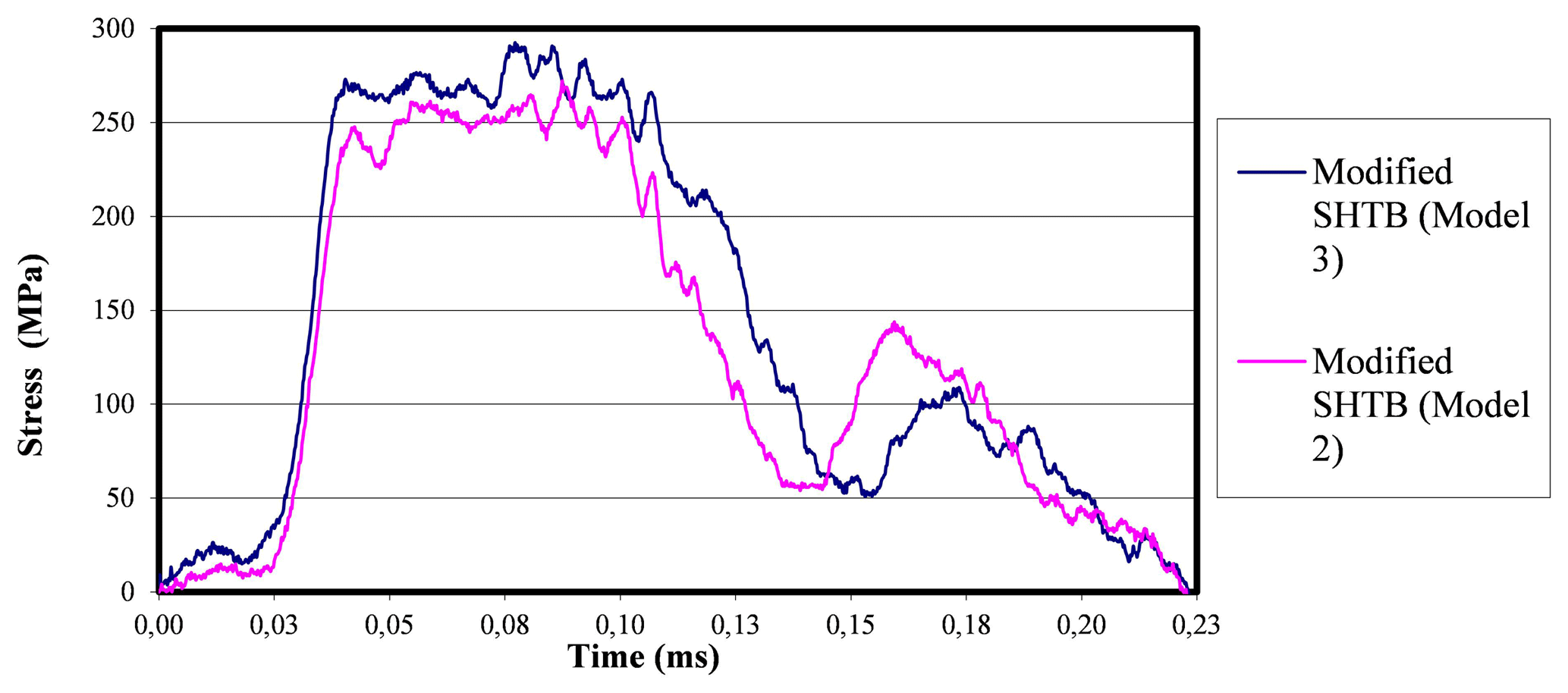
Figure 26Incident stress-time curves pertinent to the actual experiment at 3.5 bar when using 1 mm thick and no damping rings.
Observing Fig. 26 shown above, some differences between the two waves can be noted, although the differences are not too relevant. The damped experiment receives a somewhat higher impact in intensity and amplitude, but this is due to the imprecision of adjustment in the impact of the projectile, in which the pressures can be varied, obtaining different impacts. However, Fig. 27 shows the contrast of the reflected waves in both systems, in which the interruption device provides important differences.
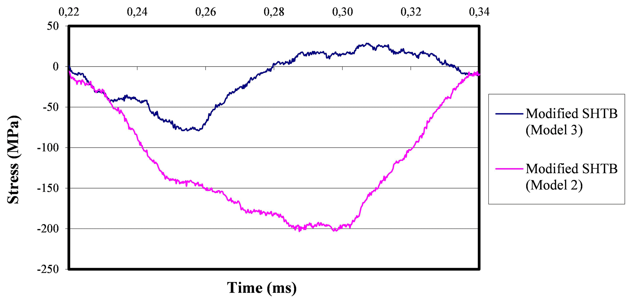
Figure 27Reflected stress-time curves pertinent to the actual experiment at 3.5 bar when using 1 mm thick and no damping rings.
The differences between these curves are very significant due to the interruption device, which will take care of absorbing much of the incident wave before reaching the end of the bar and consequently the reflected wave at the end of the incident bar is much lower than that of the undamped test. Therefore, it can be noted that the device absorbs a significant part of the impact.
It can be observed that the elongation is very small (0.0042 µm) and the specimen does not break, since its failure strength corresponds to a failure elongation around 0.027 µm, which is six times greater. Therefore, the one-dimensional wave theory cannot certainly be applied to study this case. The optimal method to study this experiment can be accomplished by mounting a strain gauge in the area of maximum deformation of the specimen so that the stress levels can be deduced from there. In this article only the waves from the strain gauges mounted on the bars are studied, leaving the analysis of the proposal of including an extra strain gauge mounted on the specimen for future works.
Figure 28Stress-time curve pertinent to the actual experiment when using 1 mm thick damping rings (transmission bar).
The observed maximum stress value is much higher than that obtained in the experiment without activating the interruption device. This occurrence is due to the fact that the interruption device absorbs part of the incident wave, which is transmitted through the casing to the transmission bar. It is also possible to observe an area of positive slope in which inflection points appear to occur before reaching such maximum value. The first one is due to the conditions of the impact, but the second may be due to the activation of the device. This can be deduced because such inflection point appears at a stress level of approximately 42 MPa, while the stress in the undamped test reached 38 MPa. This small difference can be attributed to the slight difference in impacts of both experiments.
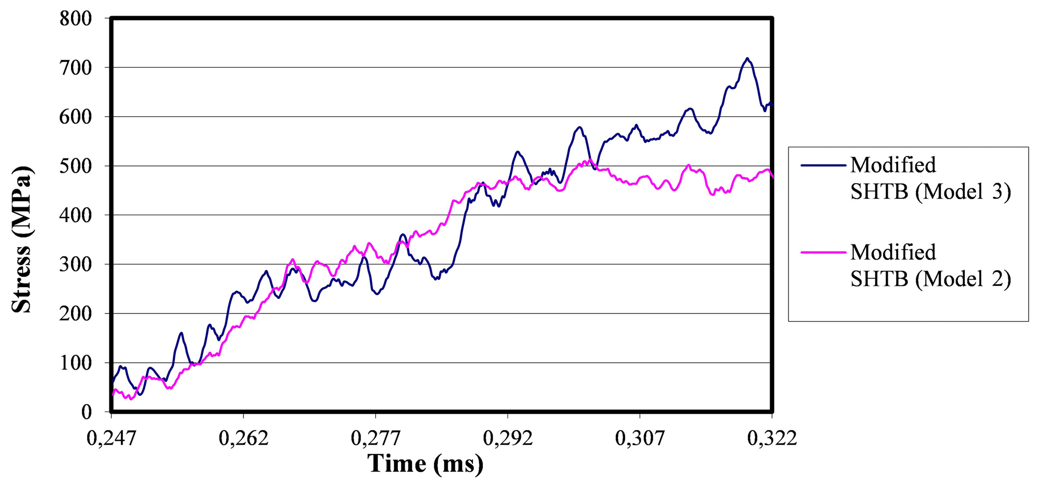
Figure 29Stress-time curves pertinent to the actual experiment at 3.5 bar when using 1 mm thick and no damping rings.
In this case the second inflection point could be the limit at which the wave transmitted by the specimen would arrive without the overlap with the wave transmitted by the interruption device. The following experiments attempt to reproduce these results to see the phenomenon more clearly. After having studied the damped test with 1 mm thick damping rings and failed to achieve the objective, which is to interrupt the modified SHTB, rings with a smaller thickness are studied.
Two experiments on SiC-reinforced ZC71 magnesium alloy, buffered with 0.8 mm and 0.5 mm thick damping rings are accomplished at an impact pressure of 3.5 bar. The data obtained are analyzed comparing them with both those of the undamped test and with the experiments accomplished when using 0.1 mm thick damping rings.
The data relevant to the strain gauge placed in the incident bar are studied first.

Figure 30Incident and reflected stress-time curves pertinent to the actual experiment at 3.5 bar when using 0.8 and 0.5 mm thick damping rings.
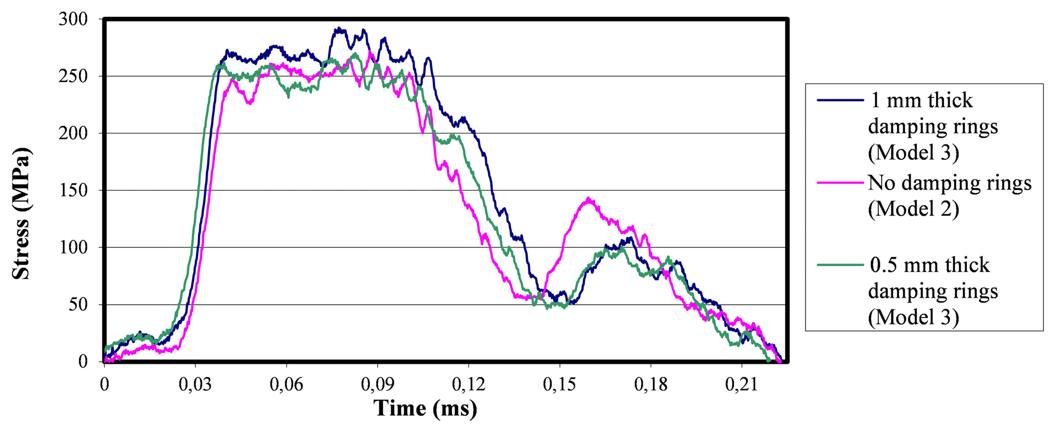
Figure 31Incident stress-time curves pertinent to the actual experiment at 3.5 bar when using 1 mm thick, 0.5 mm thick, and no damping rings.

Figure 32Reflected stress-time curves pertinent to the actual experiment at 3.5 bar when using 1 mm thick, 0.5 mm thick, and no damping rings.
A more severe impact on the damped test with 0.8 mm thick rings is observed due to the imprecision of the impact pressure regulator. Therefore, due to a weaker damping effect than that of the rings with smaller thickness, a reflected compressive wave is also observed in the case of 0.8 mm thick rings. To demonstrate the greatest damping effect in the case of lower thicknesses, the proportion of incident wave that in each case is returned in the form of reflected wave is studied. Thus,
-
Experiment with 0.8 mm thick damping rings:
-
Maximum incident stress (σmax I)=308 MPa
-
Maximum reflected stress (σmax R)=60 MPa
-
Ratio = ( %
-
-
Experiment with 0.5 mm thick damping rings:
-
Maximum incident stress (σmax I)=268 MPa
-
Maximum reflected stress (σmax R)=45 MPa
-
Ratio %
-
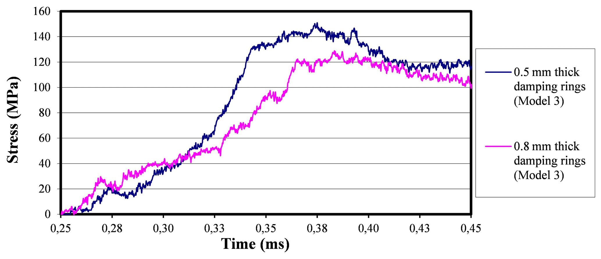
Figure 33Stress-time curves found in the transmission bars pertinent to the actual experiment at 3.5 bar when using 0.8 mm thick and 0.5 mm thick damping rings.
In the case of lower thickness, the interruption device absorbs a greater proportion of incident wave, resulting in a reflected wave of less intensity as expected. This is because the interruption of the experiment is more severe when using lower thicknesses in the damping rings, because they offer greater resistance to the deformation of the specimen. In the damped experiment with 0.8 mm thick rings, the impact is too strong to be able to contrast waves with those of previously studied experiments. The damped experiment with 0.5 mm thick rings has a similar impact than that of the previous experiments. The incident waves are shown in Fig. 31, including the damped tests with ring thicknesses of 1 and 0.5 mm, and the undamped experiment, all of which tested at 3.5 bar of pressure.
It can be observed that the incident waves have quite similarity, especially the 0.5 mm thick damped experiment and the undamped one. Once the similarity in the impact conditions in the three experiments are verified, the reflected waves are analyzed.
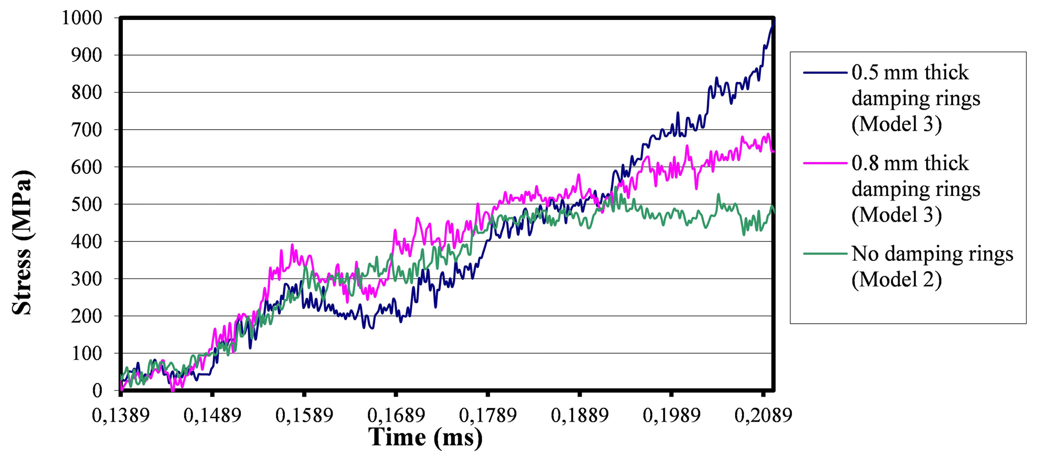
Figure 34Stress-time curves pertinent to the actual experiment at 3.5 bar when using 0.8 mm thick, 0.5 mm thick, and no damping rings.
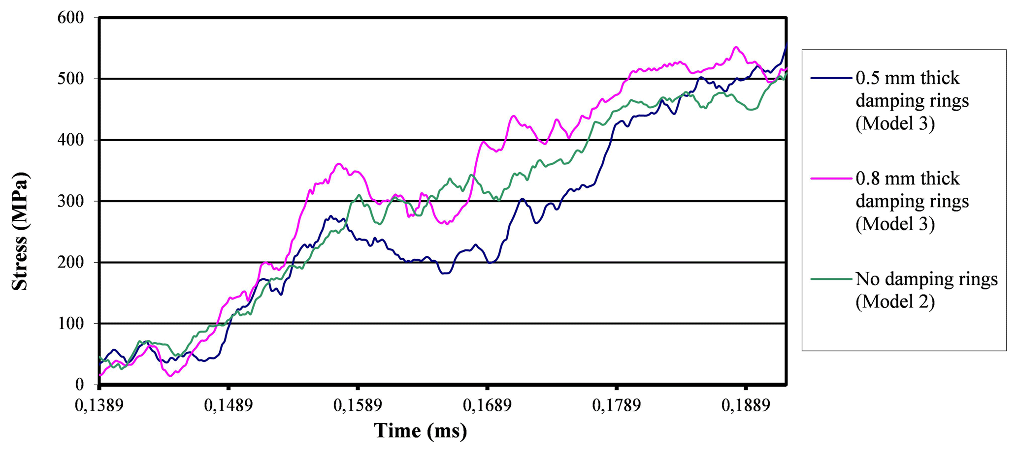
Figure 35Stress-time curves pertinent to the actual experiment at 3.5 bar when using 0.8 mm thick, 0.5 mm thick, and no damping rings.
It is clearly seen how the reflected waves decrease their intensity when using smaller ring thicknesses. Since the reflected wave is inversely related to the buffering intensity, it can be concluded that when decreasing the ring's thickness, the buffering effects increase.
The transmitted waves in the interrupted experiments are analyzed below in Fig. 33.
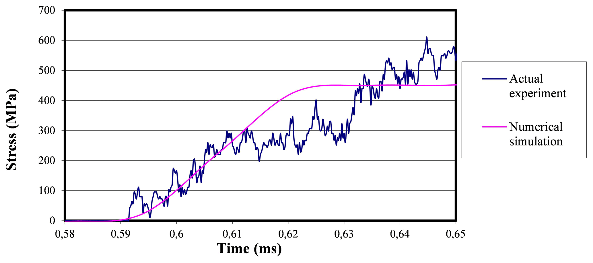
Figure 36Comparison between the stress-time curves obtained by accomplishing both the actual experiment in the laboratory and the numerical simulation when using 1 mm-thick damping rings.
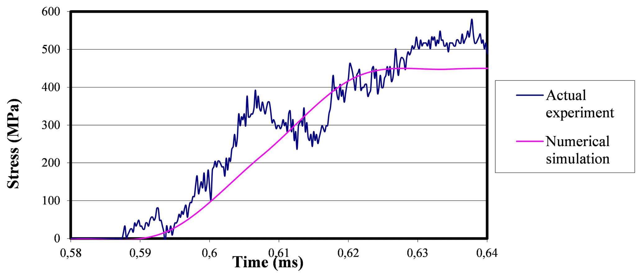
Figure 37Comparison between the stress-time curves obtained by accomplishing both the actual experiment in the laboratory and the numerical simulation when using 0.8 mm-thick damping rings.
Figure 33 shows very high stress values found in the transmission bar since the interruption device acts as a bridge between the incident wave and the transmission bar, causing it to acquire more similar stress values to the incident wave, as the damping rings' thickness decreases. Unfortunately, data are lost when the interruption device starts its performance.
The above-shown curves look similar until the interruption device starts its performance. Then the curves become divergent.
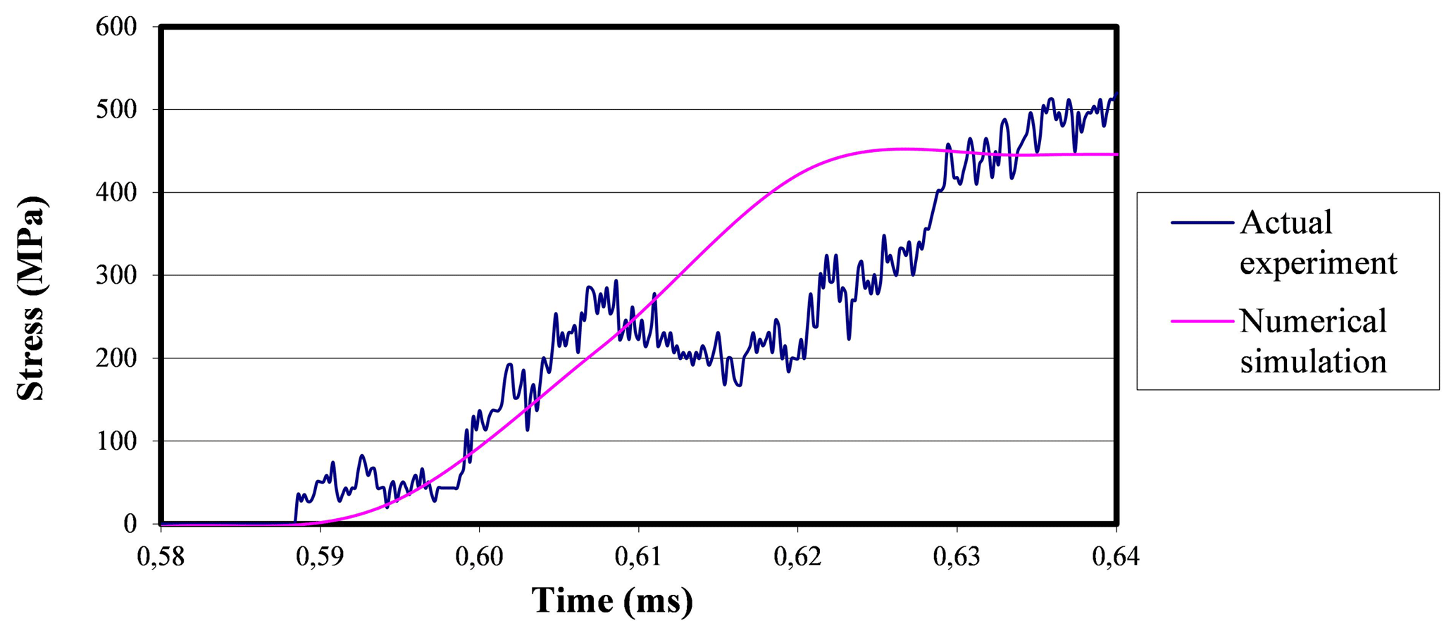
Figure 38Comparison between the stress-time curves obtained by accomplishing both the actual experiment in the laboratory and the numerical simulation when using 0.5 mm-thick damping rings.
Therefore, it can be noted that the specimen reaches a 500 MPa value of tensile stress, but from that moment onwards it is not possible to continue studying it with the information provided by the strain gauges placed in both bars.
Both models (experimental and numerical) are compared here below when 1, 0.8, and 0.5 mm thick lead damping rings are used. It is taken into account that stress values are taken in the center of the specimen when dealing with the simulated model, while in the actual experiments one-dimensional wave theory is applied on the transmission bar until the interruption device starts its performance.
Figure 36 shows the stress-time curve at the center of the specimen for the numerical simulation, and the assumed stress-time curve in the specimen obtained by applying the one-dimensional wave theory for the actual experiment when using 1 mm thick lead damping rings.
It can be noted that both curves travel through similar paths until the interruption device starts interrupting the process, what momentarily increases the stress levels. It is also possible to observe a region within the graph in which the wave relevant to the actual experiment deviates from the path by which the numerical curve travels through and therefore they follow different directions. Therefore, the experimental wave gets a different trajectory with respect to the simulated wave.
Figure 37 shows the comparison between both stress-time curves when 0.8 mm thick lead damping rings are used.
In this case the curves are more similar even than in the 1 mm thick case. The curve pertinent to the lab experiment tends to follow that of the numerical simulation, up to a point in which the interruption device starts its performance on the transmission bar causing the stress levels to increase considerably. Finally, the 0.5 mm thick case is studied.
Figure 38 shows the similarity found between both stress-time curves during the left region until the interruption device starts its performance. This occurrence evidences the difference between the two curves. As in Fig. 36, the difference in the actual experiment curve becomes more evident, possibly due to the application of the one-dimensional wave theory, which may not be entirely appropriate for this model.
During the experimental tests, after the impact, there is a portion of lead that escapes in the gap between the incident bar and the interruption device, in addition to another tiny part that remains inside the interruption system as a contact area. This increases the opposition of the specimen to deform and therefore, lower strain levels can be found in the FE values.
A numerical analysis of the SHTB tests using an external interruption device has been accomplished using FE method. Different strain rates have been obtained by using different impact pressures due to the effect of using different projectile lengths but maintaining the same velocity and pressure of the projectile in every experiment. It has been observed that the necking effect on the specimen takes place in the part of the specimen which is closest to the incident bar, since the maximum stresses are concentrated therein. Therefore, such part of the specimen undergoes the maximum strain values.
The modified SHTB model when increasing the bar ends (Model 2) has been compared with the unmodified SHTB apparatus (Model 1). High-strain-rate tensile experiments are performed on the ZC71 alloy specimens using damping rings made of lead. The differences between such experiments are minimal and may therefore be neglected. The simulations provide complementary information to the experiments and an in-depth understanding of the specimen behaviour.
The observed differences between them are significant and in some cases 1-D stress wave propagation assumption becomes a challenging issue. However, when analyzing the stress–strain conditions in both models, the stress in the specimen results diminished when using Model 2 and therefore failure is avoided even when maintaining high-rate loading.
The influence of the thickness of the damping rings on the interruption of the model has been numerically and experimentally demonstrated. It is observed that at lower thicknesses, the buffering effect becomes more intense, and there is a range of thicknesses within which such damping effect turns out to be optimal, which is around 0.8 mm. This conclusion has been reached by studying the deformation in the specimen and the strain rate levels reached in the specimen.
In view of this research, it has been numerically demonstrated that the thickness of the damping rings is a factor that can resolutely influence the results of the modified SHTB experiments. Therefore, when varying the thickness of the rings the damping effect also results increased. This was demonstrated by studying the strain levels and the strain rate levels reached by the specimen. It has been numerically shown that the volume of the interruption device is not a factor that decisively influences the damping of the model, conclusion derived from the study of the specimen's strain, which was numerically validated in previous studies.
In addition, the modified SHTB using the SiC-reinforced ZC71 magnesium alloy specimen has been numerically validated, avoiding the specimen's failure by optimally buffering the experiment using 0.8 mm thick lead damping rings. However, it should be emphasized that the validity of the conclusions is limited to the materials having a behaviour resembling the materials considered here in.
The data are not publicly accessible.
RAGL conceived the presented idea, developed the theory, carried out the experiments, co-wrote the manuscript with the support of JMdRC, and supervised the findings of this work. JMdRC verified the analytical methods, encouraged RAGL to research the specific properties of the alloy, and co-wrote the manuscript. All authors discussed the results and conclusions contributing to the final manuscript.
The authors declare that they have no conflict of interest.
The authors wish to thank Universidad CEU San Pablo (Madrid, Spain) for facilities and resources provided. The authors would like to express their gratitude to Carlos III de Madrid Engineering Department.
This paper was edited by Zbigniew Gronostajski and reviewed by two anonymous referees.
Achenbach, J. D.: Wave Propagation in Elastic Solids, North-Holland Series in Applied Mathematics and Mechanics, North Holland, 1973.
Albertini, C. and Montagnani, M.: Wave-Propagation Effects in Dynamic Loading, Nucl. Eng. Des., 37, 115–124, 1976.
ASTM E8/E8M-13a: Standard Test Methods for Tension Testing of Metallic Materials, ASTM International, West Conshohocken, PA, available at: https://www.astm.org/ (last access: October 2017), 2013.
Böhme, W.: The influence of stress waves on the dynamic crack tip loading in three-point bend impact testing, Proc. Int. Conf. IMPACT '87, Bremen, Germany, edited by: Chiem, C. Y., DGM Informationsgesellschaft mbH, Impact Loading and Dynamic Behavior of Materials, 1, 305–311, 1988.
Dongfang, M., Danian, Ch., Shanxing, W., Huanran, W., Yanjun, H., and Canyuan, C.: An interrupted tensile testing at high strain rates for pure copper bars, J. Appl. Phys., 1, 108, 114902, https://doi.org/10.1063/1.3516475, 2010.
del Río, T., Barbero, E., Zaera, R., and Navarro, C.: Dynamic tensile behaviour at low temperature of CFRP using a split Hopkinson pressure bar, Composites Sci Technol., 65, 61–71, 2005.
El-Magd, E. and Abouridouane, M.: Characterization, modelling and simulation of deformation and fracture behaviour of the light-weight wrought alloys under high strain rate loading, Int. J. Impact Eng., 32, 741–758, 2006.
Essa, Y. and Pérez, J.: Effect of the strain rate and temperature on the mechanical behaviour of a Mg–5 % Zn alloy reinforced with SiC particles, J. Mater. Process. Technol., 143–144, 856–859, 2003.
Essa, Y., Fernández, J., and Pérez, J.: Experimental Study of the Strain Rate and Temperature Effects on the Mechanical Behavior of a Magnesium-Silicon Carbide Composite, J. Testing Evaluation, 31, 449–457, 2003.
Essa, Y., Lopez-Puente, J., and Perez-Castellanos, J. L.: Numerical simulation and experimental study of a mechanism for Hopkinson bar test interruption, J. Strain Anal. Eng. Des., 42, 163–172, 2007.
Field, J. E., Walley, S. M., Proud, W. G., Goldrein, H. T., and Siviour, C. R.: Review of experimental techniques for high rate deformation and shock studies, Int. J. Impact Engineering, 30, 725–775, 2004.
Gama, B. A., Lopatnikov, S. L., and Gillespie, J. W.: Hopkinson bar experimental technique: a critical review, Appl. Mech. Rev., 57, 223–250, 2004.
Gerlach, R., Kettenbeil, C., and Petrinic, N.: A new split Hopkinson tensile bar design, Int. J. Impact Eng., 50, 63–67, 2012.
Godunov, S. K. and Romenskii, E. I.: Elements of continuum mechanics and conservation laws, Springer Science & Business Media, 2003.
González-Lezcano, R. and del Río, J. M.: Numerical analysis of the influence of the damping rings' dimensions on interrupted dynamic tension experiment results, J. Strain Anal. Eng. Des., 50, 594–613, 2015a.
González-Lezcano, R. and del Río, J. M.: Influence of the Projectile's Length on Interrupted Dynamic Tension Experiment Results, Global Journal of Researches in Engineering, Civil And Structural Engineering, vol. 15, 17–24, 2015b.
González-Lezcano, R. and del Río, J. M.: Influence of Damping Ring Material on Dynamic Tensile Tests, Int. J. Eng. Technol. (IJET), 9, 1107–1120, 2017.
González-Lezcano, R., Essa, Y., and Pérez, J.: Numerical analysis of interruption process of dynamic tensile tests using a Hopkinson bar, J. Phys. IV, 110, 565–570, 2003.
Gray, G. T.: Classic Split-Hopkinson Pressure Bar Testing, Materials Park, OH, ASM International, 4–476, 2000.
Hamouda, A. and Hashmi, M.: Testing of composite materials at high rates of strain: advances and challenges, J. Mater. Process. Technol., 77, 327–336, 1998.
Harding, J. and Welsh, L.: A Tensile Testing Technique for Fibre-Reinforced Composites at Impact Rates of Strain, J. Mater. Sci., 18, 1810–1826, 1983.
Khlif, M., Masmoudi, N., and Bradai, C.: Polypropylene tensile test under quasi-static and dynamic loading, Materials Science and Technology Conference and Exhibition 2012, 567–574, 2012.
Kolsky, H.: An Investigation of the Mechanical Properties of Materials at very High Rates of Loading, P. Phys. Soc. Lond. B, 62, 676, https://doi.org/10.1088/0370-1301/62/11/302, 1949.
Lindholm, U. and Yeakley, L.: High Strain-Rate Testing – Tension and Compression, Exp. Mech., 8, 1–9, 1968.
Lloyd, D. J.: Particle reinforced aluminium and magnesium matrix composites, Int. Mater. Rev., 39, 1–23, 1994.
Nicholas, T.: Tensile Testing of Materials at High-Rates of Strain, Exp. Mech., 21, 177–185, 1981.
Oosterkamp, L. D., Ivankovic, A., and Venizelos, G.: High strain rate properties of selected aluminium alloys, Mech. Sci. Eng. A, 278, 225–235, 1999.
Pérez-Martín, M. J., Erice, B., and Gálvez, F.: On the Loading-rate Dependence of the Al 7017-T73 Fracture-initiation Toughness, Procedia Materials Science, 3, 1026–1031, 2014.
Resnyansky, A.: Study of influence of loading method on results of the split Hopkinson bar test, Structural Failure and Plasticity (IMPLAST), 597–602, 2000.
Reyes, A., Hopperstad, O. S., Lademo, O. G., and Langseth, M.: Modeling of textured aluminium alloys used in a bumper system: material tests and characterization, Comp. Mater. Sci., 37, 246–268, 2006.
Richter, F., Köppe, E., and Daum, W.: Tracking Deformation History in Split Hopkinson Pressure Bar Testing, in: Materials Today, 3, 1139–1143, 2016.
Smerd, R., Winkler, S., Salisbury, C., Worswick, M., Lloyd, D., and Finn, M.: High strain rate tensile testing of automotive aluminium alloy sheet, Int. J. Impact Eng., 32, 541–560, 2005.
Staab, G. and Gilat, A.: A Direct Tension Split Hopkinson Bar for High-Strain Rate Testing, Bethel, Soc experimental mechanics Inc., 1990.
Swantek, S., Wicks, A., and Wilson, L.: An optical method of strain measurement in the split Hopkinson pressure bar, Proceedings of Imac-Xix: a Conference on Structural Dynamics, 4359, 1471–1477, 2001.
Thakur, A., Nemat Nasser, S., and Vecchio, K.: Dynamic Bauschinger effect, Acta Mater., 44, 2797–2807, 1996.
Verleysen, P. and Degrieck, J.: Experimental investigation of the deformation of Hopkinson bar specimens, Int. J. Impact Eng., 30, 239–253, 2004.
Verleysen, P., Benedict, V., Verstraete, T., and Joris, D.: Numerical study of the influence of the specimen geometry on split Hopkinson bar tensile test results, Lat. Am. J. Solids Struc., 6, 285–298, 2009.
Yang, X., Xiong, X., Yin, Z., Wang, H., Wang, J., and Chen, D.: Interrupted Test of Advanced High Strength Steel with Tensile Split Hopkinson Bar Method, Exp. Mech., 54, 641–652, 2004.
Whitehouse, A. F., and Clyne, T. W.: Effects of reinforcement content and shape on cavitation and failure in metal-matrix composites, Composites, 24, 256–261, 1993.