the Creative Commons Attribution 4.0 License.
the Creative Commons Attribution 4.0 License.
 | 03 Jun 2019
Experimental study of immersion ratio and shaft inclination angle in the performance of a surface-piercing propeller
Seyyed Mostafa Seyyedi
Rouzbeh Shafaghat
Mohioddin Siavoshian
Surface-piercing propellers have been widely used in light and high-speed vessels because of their superior performance. Experimental study of these propellers is one of the most reliable and accurate ways which can provide details about the performance and effect of different design parameters on the performance of the surface-piercing propellers. In this research, a five-blade surface-piercing propeller was tested in the free surface water tunnel of Babol Noshirvani University of Technology in order to expand the available experimental data and database for future engineering designs. The effects of immersion ratio and shaft inclination angle on the propeller's efficiency and hydrodynamic coefficients were examined. A free surface water tunnel and a calibrated dynamometer with the measurability of the thrust forces and the torque of a propeller were used for this purpose. Comparing the obtained results with the existing semi-experimental equations shows that the equations presented in various geometric conditions are not accurate enough, and developing the existing database is necessary. The details of the obtained results showed that the hydrodynamic coefficients of the thrust and torque increased by increasing the immersion ratio, but the coefficient of hydrodynamic thrust and efficiency reduced. The results also indicated that the coefficient of torque increased by increasing the shaft inclination angle. The highest efficiency of the propeller was achieved in the range of 40 %–50 % immersion ratios at all angles of shaft inclination. For all immersion ratios, the maximum and minimum efficiencies were obtained at 0 and 15 shaft inclination angles, respectively. The best efficiency of the propeller was at 50 % immersion ratio and zero shaft inclination angle.


Today, more than 90 % of world trade belongs to marine transportation because of the low cost of transferring passengers, goods, and raw materials (IMO, 2012). One of the drawbacks of marine transportation is that this process is slow and time-consuming, but by the development of new technologies and industries, the transportation speeds have been increased considerably. Surface-piercing propellers are a special kind of super-cavitating propeller which act in semi-submerged conditions and on free surfaces. They are known as one of the suitable propulsion systems for increasing speed and are able to create thrust in different conditions. On the other hand, regarding the distance of propellers to the body of the vessel, using them in shallow waters is not limited. Despite the important studies about surface-piercing propellers, additional investigation in order to achieve real behavior and desired performance of surface-piercing propellers is still necessary. Previous studies show that there is not yet a unique and reliable algorithm for selection of surface-piercing propellers. Based on the current design process for the selection of propellers, the most important step is determining the minimum thrust and maximum torque of the propeller. These values can be obtained from the hydrodynamic coefficients that are determined by experimental, theoretical, and semi-experimental methods. Each of these methods has their own defects and disadvantages, along with their advantages. Despite developing theoretical methods, using physical modeling and experiments is still the most reliable method for designing the surface-piercing propellers.
Various experimental studies have been conducted on the surface-piercing propellers in order to evaluate the performance of these propellers. Shiba (1953) published the first study on the effect of the Weber number on the blades of the surface-piercing propellers. Using a comprehensive experimental study he suggested 180 as the low limit of the Weber number to generalize the results of model experiments to the real prototype. The results of Hadler and Hecker (1968) provided a suitable basis for validation of theoretical research. They calculated the thrust and efficiency of a partially immersed propeller using a super-cavitating propeller with two and three blades and three super-cavitating propellers with three blades. They studied the effect of different diameters and an expanded area ratio and compared their results with the results of a submerged propeller. Considering the vertical force, they found that immersion rate is the dominant factor in determining the hydrodynamic parameters' value. This suitable value was between 30 % and 50 %, which can double the thrust. In another work, Shields (1968), by studying several partially immersed super-cavitating propellers, observed that in a Froude number larger than 4, the Froude number has no effect on the hydrodynamic parameters; but the reduction of the Froude number increases the force imposed on the blades. Experimental study of partially submerged propellers in a cavitation tunnel by Kruppa (1972) showed that slight changes in the immersion ratio or yaw angle have impacts on the balance and efficiency of the propeller and modify the critical advance coefficient (flow transfer from a partially ventilated regime to a fully ventilated regime). Liu and Zho (1988) experimentally studied the specifications of propellers with partial immersion with three and five blades. Their results showed that the performance of surface-piercing propellers is very similar to the performance of conventional propellers except in three zones of partially ventilated, unstable transfer and a fully ventilated zone.
Rose and Kruppa (1991) published the results of a series of tests on the surface-piercing propellers and the measured forces imposed on the propeller. Rose et al. (1993) studied the interaction of vessel and propeller. Results of their test on two real and model vessels showed that magnitudes of vertical and lateral forces, as well as momentum, can have important impacts on the vessels' efficiency. Their experimental study also showed that an increase in a positive yaw angle will increase the thrust. Olofsson (1996) measured the dynamic and time mean of forces on each propeller's blade. He studied the force and flow characteristics in a surface-piercing propeller experimentally to determine the hydrodynamic efficiency of the propeller. He also examined the effect of Froude and cavitation numbers on the hydrodynamic coefficients for different advance coefficients, yaw angles, and shaft inclination angles. Ferrando and Scamardella (1996) studied the propellers' efficiency in both submerged and surface-piercing conditions. Their results showed the effect of immersion ratio on the surface-piercing propellers' efficiency. Results of testing four surface-piercing propellers have been reported by Dyson (2000). The experiments were conducted to determine the mean loads and imposed loads on different intervals on the four surface-piercing propellers with the same pitch, expanded area ratio, and diameter, and different blade section, number of blades, and skew angle. Thrust and torque values in 30 % and 50 % immersion show that the immersion has a significant effect on the results, but it makes slight differences in the efficiency. Efficiency of a surface-piercing propeller with three blades and various pitch ratios in a cavitation tunnel was studied by Nozawa and Takayama (2002). Results of their research showed that by increasing the pitch ratio, thrust, and torque, the hydrodynamic coefficients increase linearly, and by increasing the pitch ratio and speed, the efficiency of a surface-piercing propeller can be increased. They also showed that the maximum efficiency is higher in the propellers with higher pitch ratios.
Performance of the surface-piercing propellers was studied experimentally by Ferrando et al. (2006, 2007). In their study on the surface-piercing propellers with five blades and different pitch ratios, the effect of immersion and pitch ratios on thrust, torque coefficients, and efficiency was studied. Then, using regression, an equation was proposed for describing the relationship between thrust and torque coefficients with advance coefficients higher than the critical value. They also developed correlations for predicting hydrodynamic coefficients for four- and five-blade propellers using the experimental results. Ding (2007) published the results of research on the surface-piercing propellers with six blades with different pitch ratios. The results showed that by changing the Froude number from 3.46 to 4.24, thrust, torque, and efficiency are relatively stable in these Froude numbers. He concluded that when the Froude number is larger than 3.5, open water tests for surface-piercing propellers can be done in atmospheric pressure and results are not sensitive to the Froude and cavitation numbers.
Experimental study of surface-piercing propellers was done by Lorio (2011) in a towing tank in non-pressurized state in which immersion ratio, yaw angle, and shaft inclination angle change. Compared to the previous studies conducted by Olofsson (1996) and Ferrando et al. (2006) (propellers were tested in 2 degrees of freedom, yaw and inclination angle, or inclination angle and immersion ratio), Lorio conducted the experiments using 3 degrees of freedom. The results showed that for a fully submerged propeller, the torque and thrust are high, but in surface-piercing propellers, although the dynamic forces are higher than the fully submerged propeller, the total thrust and torque are low. Misra et al. (2012) tested four surface-piercing propellers with four different shapes and four blades. The propellers with wedge and diamond-back sections were selected for the blades of these propellers. Three different wedge forms have been designed with 0, 30, and 60∘ angles in order to study the effect of a trailing edge (cup shape) at high speed. Regarding the experimental results, the best performance in all immersion ratios has been obtained in a propeller with 60∘ trailing edge and wedge section.
Towards the comprehensive use of experimental test data, researchers have attempted in previous years to use these results in the semi-experimental equations to obtain the hydrodynamic coefficient. Ferrando et al. (2006, 2007) developed equations for predicting hydrodynamic coefficients for four- and five-blade propellers using experimental results. In another study, Montazeri and Ghasemi (2009), using the experimental results of previous researchers, proposed a semi-experimental equation for surface-piercing propellers. In order to validate the accuracy of a semi-experimental equation, Lorio (2011) compared his experimental results with Ferrando et al.'s regression/semi-experimental equation (2007) for thrust and torque and observed that the thrust coefficient obtained by experiment is consistent with the regression/semi-experimental equation, but the torque coefficient is lower than the predicted value obtained by the regression/semi-experimental equation. Although these semi-experimental equations can be used to calculate hydrodynamic coefficients, since these equations are obtained based on the results of experimental tests and even with combining some theoretical methods, they are not suitable solutions to obtain the hydrodynamic coefficients due to the error and unsuitable accuracy caused by limited experimental data and intervals (Ferrando et al., 2017).
Regarding the problems in the analysis of surface-piercing propeller performance that are caused by the lack of a complete database for experimental data, uncertainty about the theoretical methods, and inaccuracy in the semi-experimental equations for predicting hydrodynamic coefficients, it is necessary to continue experimental research to obtain more data about thrust and torque hydrodynamic coefficients, and the efficiency of surface-piercing propellers. By expansion of research and experimental data, their results can be used for validating theoretical and numerical methods as well as improving semi-experimental equations so as to obtain reliable and efficient methods and equations for predicting the performance of surface-piercing propellers and using these methods for simulating physical phenomena in surface-piercing propellers. Considering that previous studies have focused on the four-blade propellers, experimental data and regression equations used to determine hydrodynamic coefficients of four-blade propellers have better accuracy relative to the propeller with more blades; this is while using five-blade propellers is more common in the vessels.
Experimental results indicate that a five-blade propeller always has higher thrust, torque, and efficiency than other propellers (Dyson, 2000). Previous research showed that in the experimental tests, only a limited number of propellers' sections were tested, and many operational propellers have not been studied yet. Therefore, one of the most important gaps is the lack of hydrodynamic coefficients for propellers with different sections. Since each surface-piercing propeller may show different behavior with changing the section and other geometrical parameters, development of experimental studies about five-blade surface-piercing propellers is also important. For this purpose, in this experimental study, a free surface water tunnel was used to test the five-blade surface-piercing propeller in different performance conditions. First, the free surface water tunnel and dynamometer were calibrated; then, using a five-blade surface-piercing propeller, data, hydrodynamic coefficients, and efficiency were obtained in different physical conditions and analyzed. In addition, tests were repeated for the shaft inclination angles, four immersion ratios, and 12 advance coefficients, and their results of hydrodynamic coefficients of thrust, torque, and efficiency of the propeller were reported. The ultimate aim of this research is to obtain the best state for propeller installation in which it has maximum efficiency. In addition, the obtained results were compared to the results of semi-experimental equations to provide a suitable evaluation for the accuracy of these equations in the prediction of hydrodynamic coefficients in the five-blade propellers. Experimental data in this research can also be used as a basis for developing numerical methods in order to confirm the accuracy of the results and reduce the error in semi-experimental and regression equations.
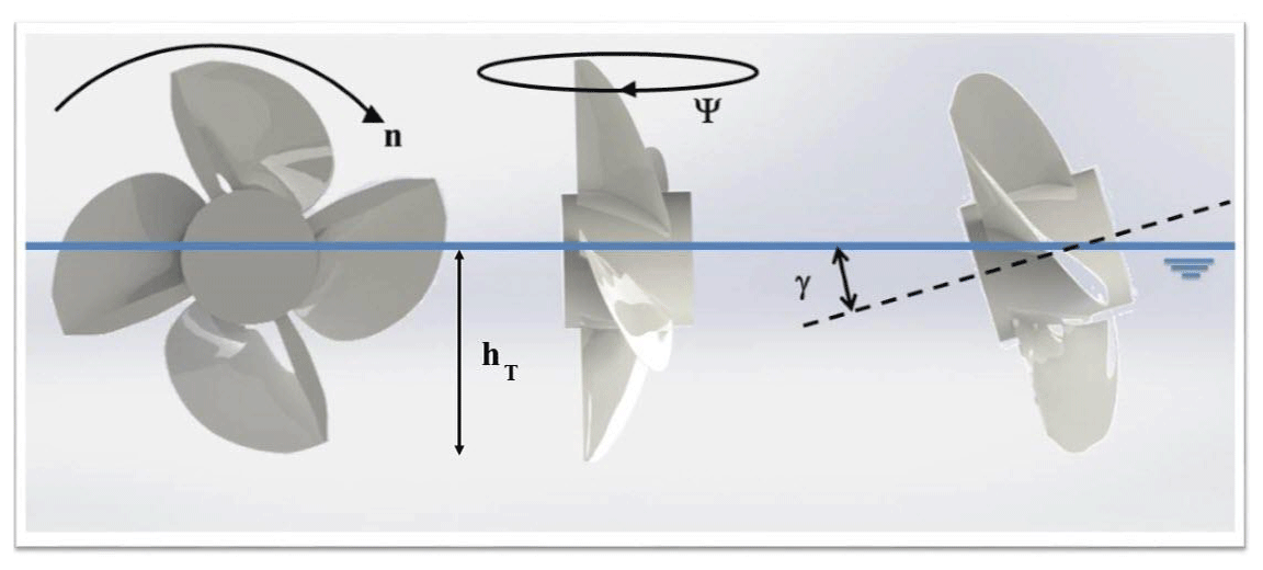
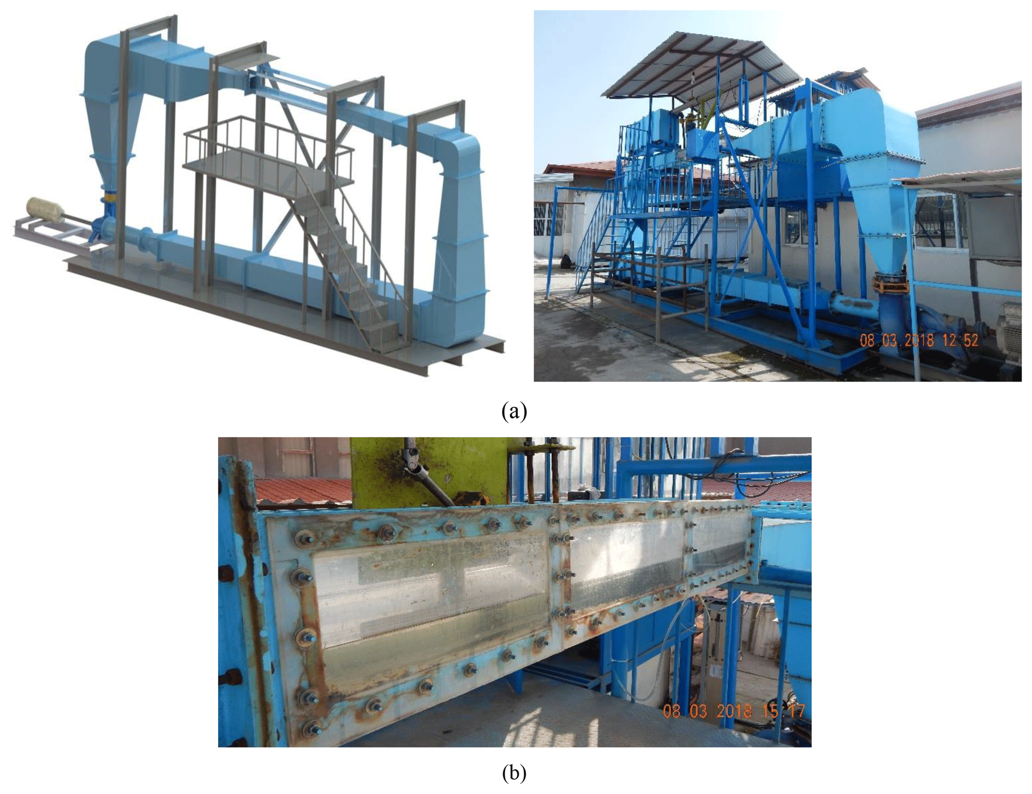
Figure 2(a) Free surface water tunnel of the Sea-based Energy Research Group at Babol Noshirvani University of Technology and (b) the test section.
Effective parameters in the performance of surface-piercing propellers can be divided into geometrical and physical parameters. Geometrical parameters include diameter (D), pitch (P), number of blades (Z), expanded area ratio (EAR), rake angle (θr), skew angle (θs), immersion ratio (It), chamber profile (f), and thickness of blade (t). Functional conditions have an important and vital role in the hydrodynamic efficiency of surface-piercing propellers along with the geometrical parameters. Advance coefficient (J), Reynolds number (Re), cavitation number (σ), Weber number, shaft inclination angle (γ), yaw angle (ψ), and Froude number (Fr) are known as the physical parameters. Figure 1 shows the different propeller location angles. Some of these parameters, including the number of blades, pitch ratio, expanded area ratio, advance coefficient, Reynolds number, and cavitation number have identical behavior to the submerged propellers. Because of the function of surface-piercing propellers in the water and air, parameters that have lower importance in the design of submerged propellers will have special importance in the design of surface-piercing propellers. Therefore, the thrust and torque can be defined as follows for the surface-piercing propellers (Ghassemi and Ghiasi, 2011):
or
Non-dimensional parameters can be defined as follows:
where υ and κ are kinematic viscosity and dynamic surface tension, hT is the immersion height of the propeller in water, and n is the rotation of the propeller. Non-dimensional hydrodynamic coefficients are obtained by calculating the mean thrust and torque of the propeller. The propeller's curve including the hydrodynamic coefficients of thrust (Kt) and torque (Kq) along with efficiency are defined as
where T is thrust, Q is torque, ρ is water density, and D is the propeller's diameter.
In this section, required equipment for the testing and calibration of the surface-piercing propellers is introduced. The experimental study for the surface-piercing propellers was conducted in the free surface water tunnel of the Sea-based Energy Research Group of Babol Noshirvani University of Technology. General specifications of the free surface water tunnel are presented in Table 1 (Seyyedi and Shafaghat, 2016).
Table 1General specifications of the free surface water tunnel and the test section (Seyyedi and Shafaghat, 2016).
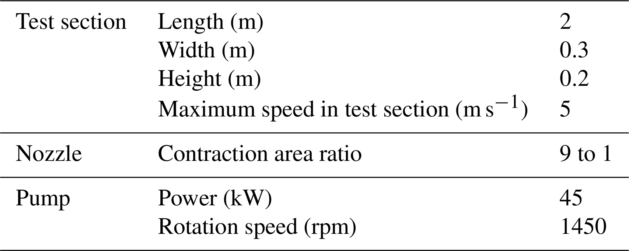
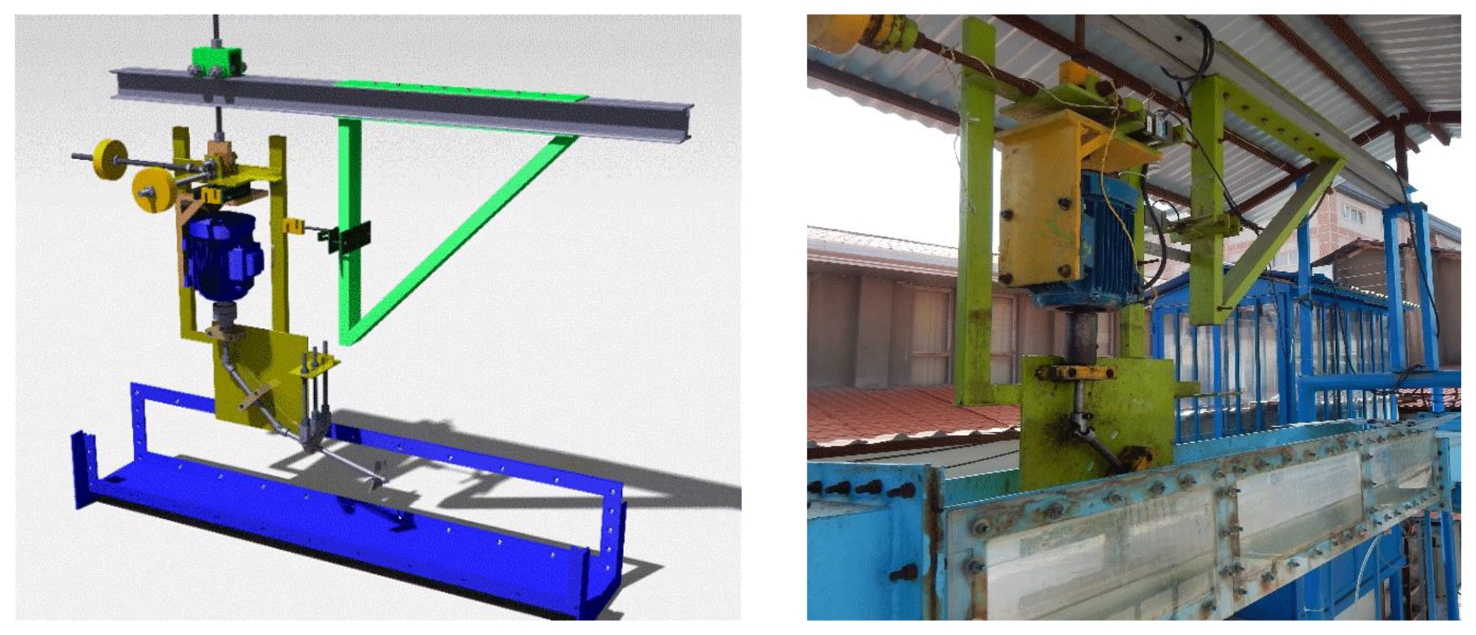
Figure 3Dynamometer and the installation details used for measuring of hydrodynamic parameters in the surface-piercing propellers.
The free surface water tunnel and the test section are shown in Fig. 2.
A dynamometer was used for measuring thrust and torque forces in different shaft inclination angles, yaw angles, and immersion ratios (see Fig. 3). This dynamometer can measure the thrust up to 981 N, torque up to 67 Nm, and rotation up to 3600 rpm.
In order to ensure the accuracy of equipment for measuring different parameters, first, the water tunnel and dynamometer were calibrated. The speed calibration was conducted in the test section using an ultrasonic flow meter (Fluxus ADM 6725, Flexim company) and its connection to a manometer (for measuring the pressure difference). The accuracy of measurements was verified by (based on the different mercury height in manometer) repeating the measurements six times. Table 2 shows the standard deviation and coefficient of variation for speed in the test section. Considering the values in the table, the standard deviation was 0.016 m s−1.
Table 2The standard deviation calculation of speed data in the test section.
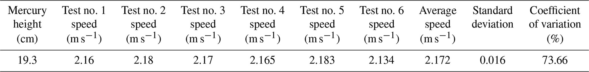
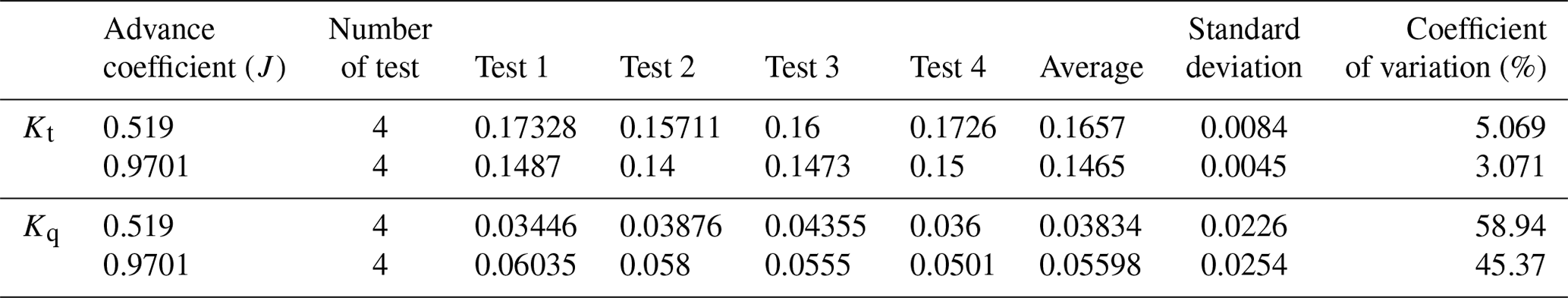
Table 3Calibration data for the shaft inclination angle at 0∘ and immersion ratio 33 % in two different advance coefficients.
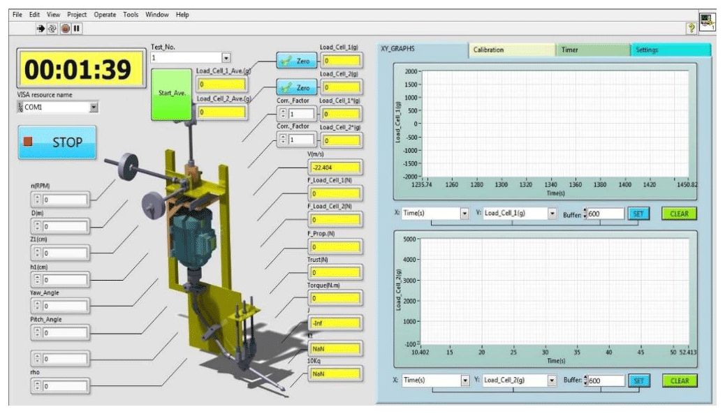
Since calculation of the thrust and torque of a propeller is one of the major goals during testing of surface-piercing propellers, the dynamometer was used to achieve this goal. Figure 4 shows the measured parameters and the locations of the corresponding sensors in the experiment.
In the next step, the tests were repeated for five states in order to calibrate the thrust and torque sensors of a dynamometer to ensure the accuracy of results for a five-blade propeller (Fig. 5). Table 3 shows a sample of calibration data for the shaft angle at 0∘ and immersion ratio 33 % in two different advance coefficients. The table shows that the obtained results have an acceptable accuracy (the mean standard deviations for the thrust and torque are less than 0.008 and 0.025, respectively).
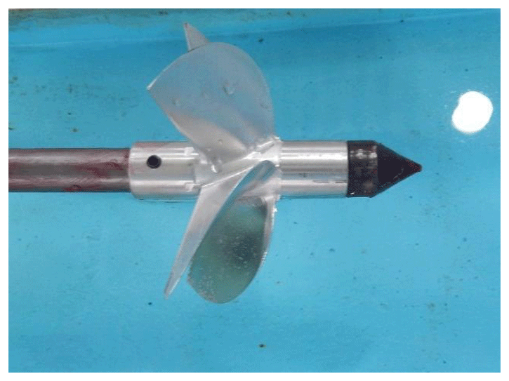
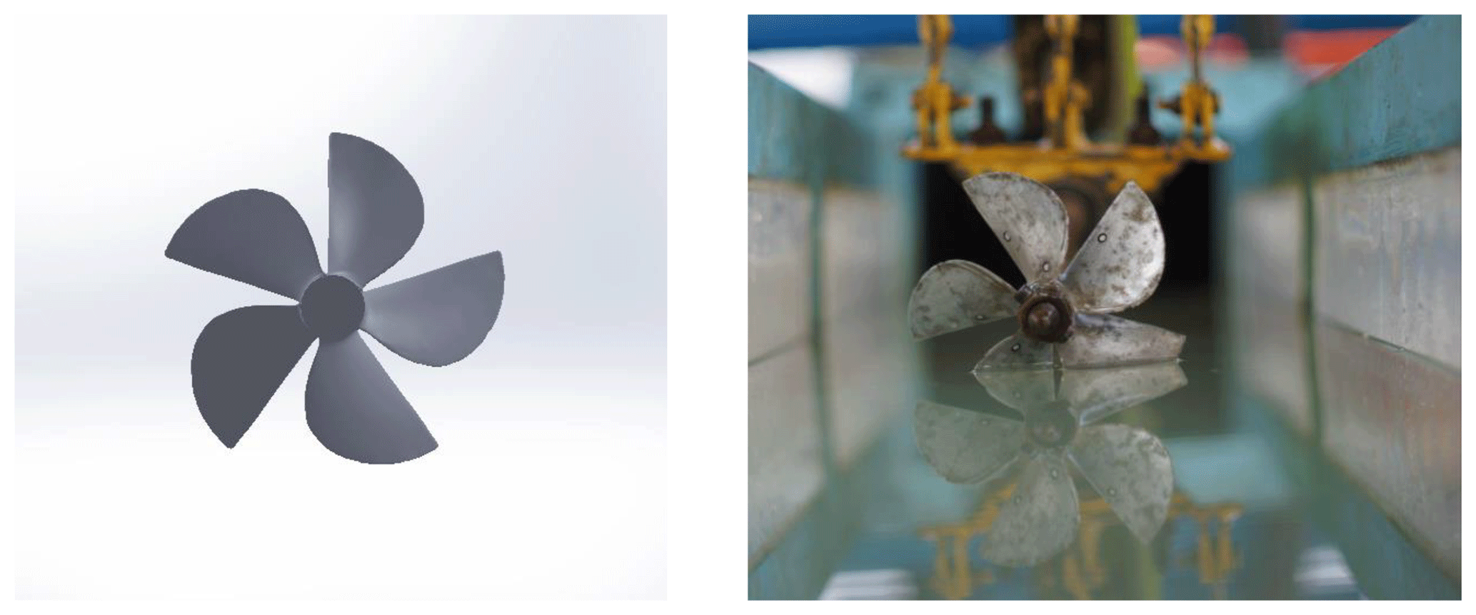
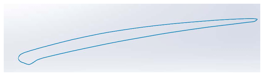
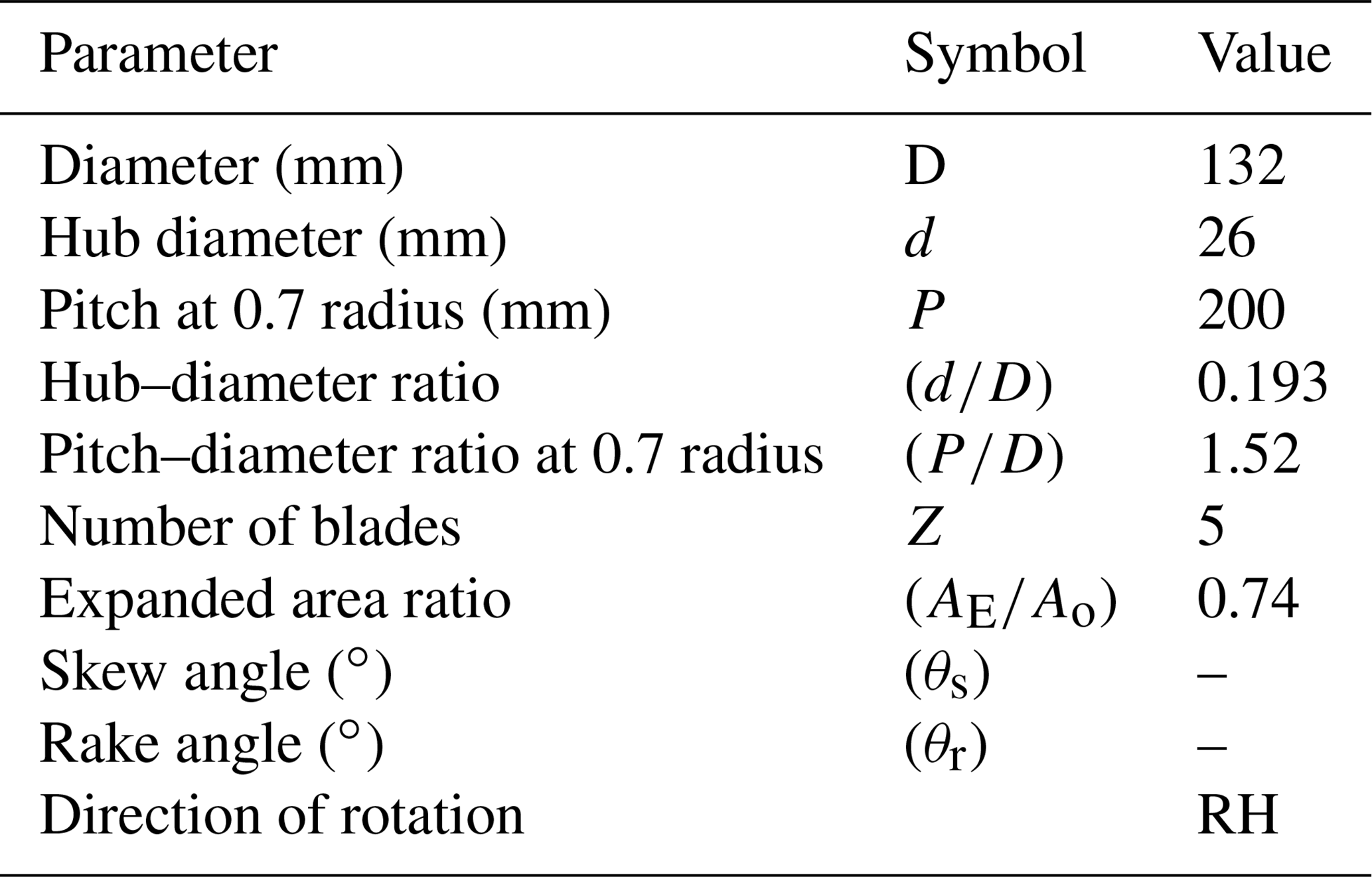
A five-blade aluminum propeller with diameter 130 mm, pitch ratio 1.52, and extended area ratio 0.74 was used in this research. The schematic and specifications of the surface-piercing propeller are shown in Fig. 6 and Table 4. The blade section shape is shown in Fig. 7, which has a sharper leading edge, and the trailing edge is cup-shaped.
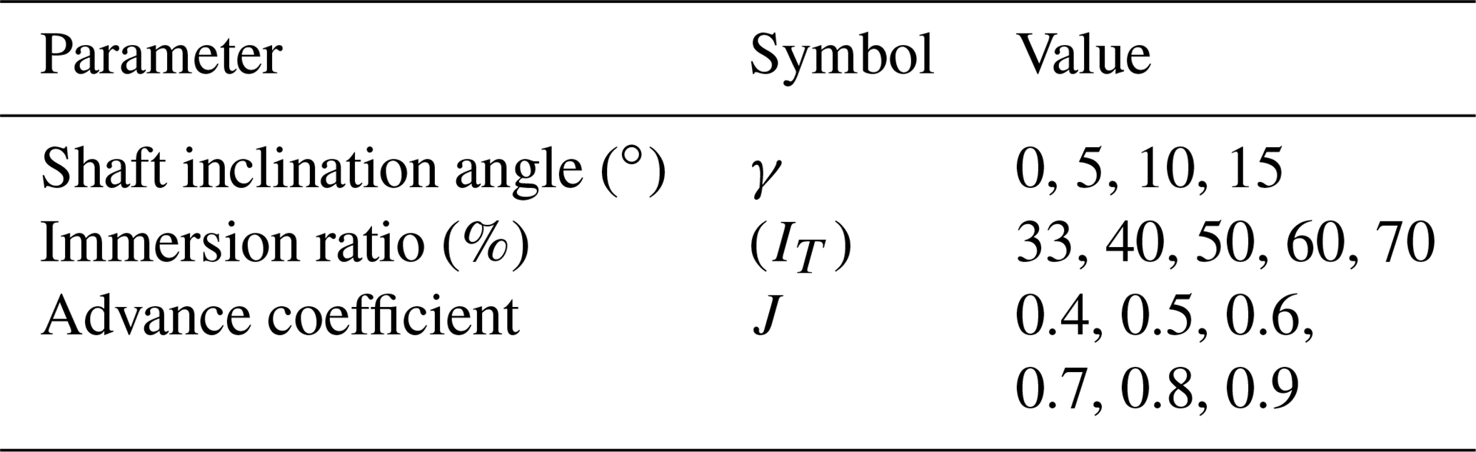
For the experimental tests eight advance coefficients (from 0.44 to 0.95), a shaft inclination angle (0 to 15∘), and five immersion ratios (33 % to 70 %) were studied, and the variation of these parameters was determined using the Shafaghat et al. (2017) research. The test parameters are shown in Table 5.
One of the conditions and limitations of conducting experiments on the surface-piercing propeller is to meet the cavitation, Froude, Weber, and Reynolds non-dimensional numbers. In addition, other effective parameters also have a major role in designing the propellers and their hydrodynamic coefficients (Shafaghat et al., 2017). Similarity rules should hold for testing the propellers in the cavitation tunnel and generalizing results of the model to a real propeller. But similarity rules do not hold for the Weber, Froude, and Reynolds numbers simultaneously in the surface-piercing propellers. Determining the Weber and Froude numbers is also another issue in testing the surface-piercing propellers. In certain conditions, we can ignore the effects of Reynolds, Weber, and Froude numbers. This is very important from a laboratory view because in these conditions, other hydrodynamic characteristics of the propeller can be determined by measuring the thrust and torque in an advance coefficient interval, and there is no need to measure the hydrodynamic characteristics of the propeller by changing the non-dimensional numbers.
Separation of boundary layers does not occur in Reynolds numbers larger than a critical value, and the effect of the Reynolds number on the hydrodynamic characteristic fades in spite of the flow regime. Results of previous research showed that the Froude number has no effect on the results and critical advance coefficients for Froude numbers larger than 4 during the functional phases of surface-piercing propellers. When the Froude number is larger than 4, it can be assumed that the air bubbles have reached their final form and the hydrodynamic specifications approach the final values asymptotically (Shiba, 1953; Olofsson, 1996). According to Shiba (1953), the effect of the Weber number, which is associated with surface tension, on hydrodynamic characteristics of propellers fades away for values larger than 180, and the results of model tests can be generalized to the real prototype. A common method used by Pastocheni et al. (2007) for generalizing the results of a model to prototype in order to design the surface-piercing propellers was determining limits for the Reynolds, Froude, and Weber numbers. They concluded their research by proposing Eq. (5). The surface-piercing propeller function curve is independent of non-dimensional numbers, and the minimum rotation required for testing the propellers, using Eq. (5), is 31.32 rps or 1850 rpm.
The experimental results were validated by considering a four-blade propeller (Olofsson, 1996). The diameter of the propeller in Olofsson (1996) was 250 mm, but due to the dimensional limitation of the test section, the diameter of the propeller has decreased to 125 mm (Fig. 8).
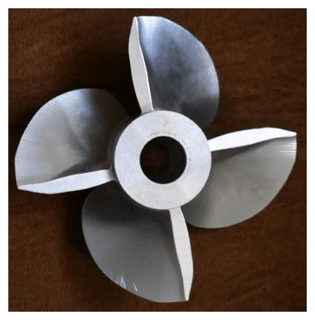
Figure 9 shows the comparison of the coefficients of thrust and torque with those of obtained from Olofsson (1996) at Fr = 2 (V=2.21 m s−1). This figure indicates that there is good agreement between the results.
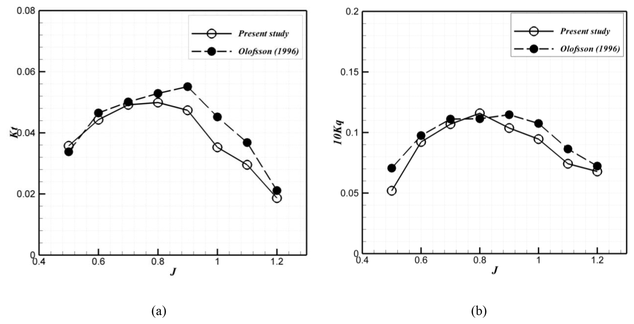
Figure 9Comparison of the coefficient of thrust (a) and torque (b) with those obtained by Olofsson at Fr = 2 (1996).
In this section, first, the results of a surface-piercing propeller test in different test conditions were compared to the hydrodynamic coefficients predicted by semi-experimental equations of Ferrando et al. (2007) and Montazeri and Ghassemi (2009). Then the effect of advance coefficients, immersion ratio, and shaft inclination angle on the hydrodynamic coefficients and efficiency were evaluated and results were analyzed. The presented data for hydrodynamic coefficients are the mean value of the results in all graphs. Generally, in previous studies, the raw experimental data have been used for comparison with values obtained by numerical or analytical methods, but in this paper, because only an experimental test is done, a continuous curve is used to observe the variations in hydrodynamic coefficients.
The comparison between the present experimental results and previous semi-experimental equations proposed by Ferrando et al. (2007) and Montazeri and Ghassemi (2009) is shown in Figs. 10 and 11. Figure 10 compares the hydrodynamic coefficients obtained by the regression equation of Ferrando et al. (2007) and Montazeri and Ghassemi (2009) with the experimental values at immersion ratios of 33 % and 50 % and a shaft inclination angle of 0∘. As seen, although both semi-experimental equations can correctly predict the increase in hydrodynamic coefficients by an increasing immersion ratio, the difference between the values predicted by these equations with the experimental tests, especially for the thrust, shows that these equations are not accurate enough. The accuracy of the equation presented by Ferrando et al. (2007) for the thrust and torque, especially in the low immersion ratio, is higher than those proposed by Montazeri and Ghassemi (2009).
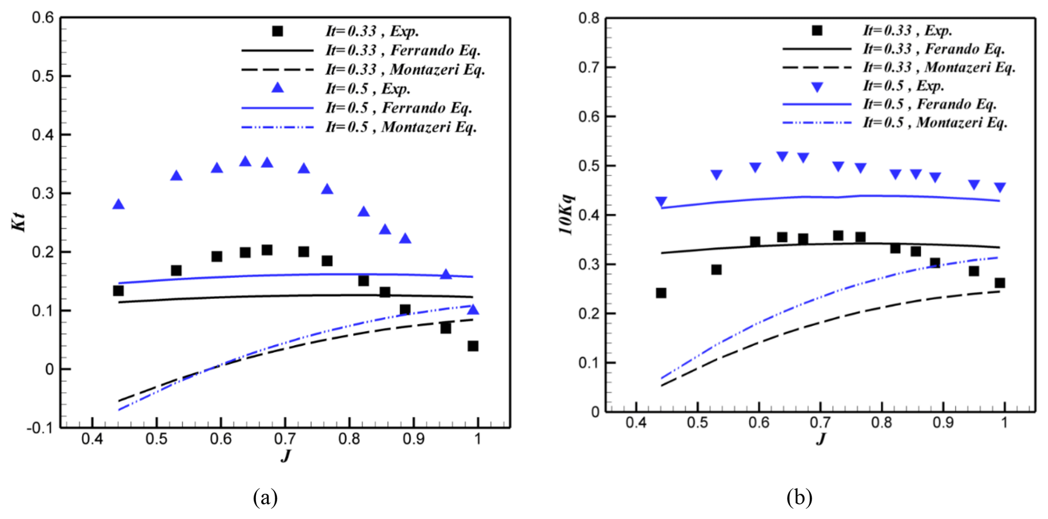
Figure 10Comparison of the hydrodynamic coefficients predicted by Ferrando et al. (2007) and Montazeri and Ghassemi (2009) semi-experimental equations and the experimental values.
Figure 11 shows the comparison between the hydrodynamic coefficients obtained by the regression equation of Ferrando et al. (2007), and Montazeri and Ghassemi (2009) with the semi-experimental values in two shaft inclination angles of 0 and 10∘ for the immersion ratio of 33 %. As seen by changing the shaft inclination angle, the hydrodynamic coefficients predicted by Ferrando and Montazeri's equations remain relatively stable, while in the experimental values, the thrust and torque hydrodynamic coefficients decrease and increase, respectively, by increasing the shaft inclination angle.
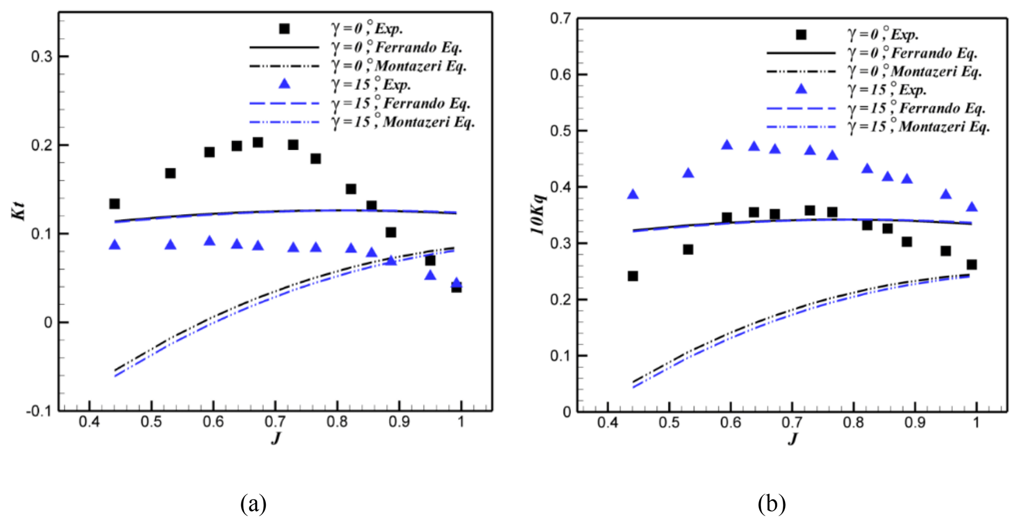
Figure 11Comparison of the surface-piercing hydrodynamic coefficients predicted using Ferrando et al. (2007) and Montazeri and Ghassemi (2009) semi-experimental coefficients with the experimental values.
The comparison indicated that semi-experimental equations do not have suitable accuracy for predicting hydrodynamic coefficients because all of the geometrical and physical parameters effective on the performance of the propellers have not been studied yet. On the other hand, semi-experimental data which are provided using a database of experimental tests are imperfect. One of these defects is the definition of equations based on the submerged area. In a fully ventilated regime, the free surface rises due to the formation of a pressure field such that the immersion cannot be measured correctly. In these equations, effects of immersion ratio and shaft inclination angle were imposed separately to determine the thrust and torque which reduce accuracy of equations. Because the experimental test data for the effect of shaft inclination angle have been used in the semi-experimental equations, the experimental data obtained in this study can be used to improve the accuracy and reduce the semi-experimental equation error.
Immersion ratio is one of the most important parameters in the performance of surface-piercing propellers. In the previous studies, Dyson (2000) and Ferrando et al. (2007) conducted their experiments for a five-blade propeller. Dyson (2000) conducted the experiments for two immersion ratios of 30 % (shaft inclination angle of 4) and 50 % (shaft inclination angle of 8), while Ferrando et al. (2007) investigated a 0.4–0.7 immersion ratio in the shaft inclination angle of 6. In Lorio's study (2011) for a four-blade propeller, the immersion ratio of 33 % to 50 % was studied with a fixed shaft inclination angle.
Figures 12 and 13 show the effect of immersion ratio on the thrust, torque, and efficiency of five-blade propellers in different advance coefficients and two fixed shaft inclination angles 0 and 10. Immersion ratio changes by maintaining a fixed shaft inclination angle in these figures. As seen in Fig. 12a and b, for the shaft inclination angle 0, as the immersion ratio increases the thrust and torque hydrodynamic coefficients increase. Similar results are obtained for the thrust and torque in Dyson (2000) and Ferrando et al. (2007). As the immersion ratio surpasses 50 %, as well as increasing the advance coefficient beyond the critical advance coefficient, the thrust will significantly reduce. Increasing the thrust and torque hydrodynamic coefficients with the increase in immersion ratio is due to the increase in effective blade area in the water and lift and drag forces on the blade which increase the thrust and torque, respectively.
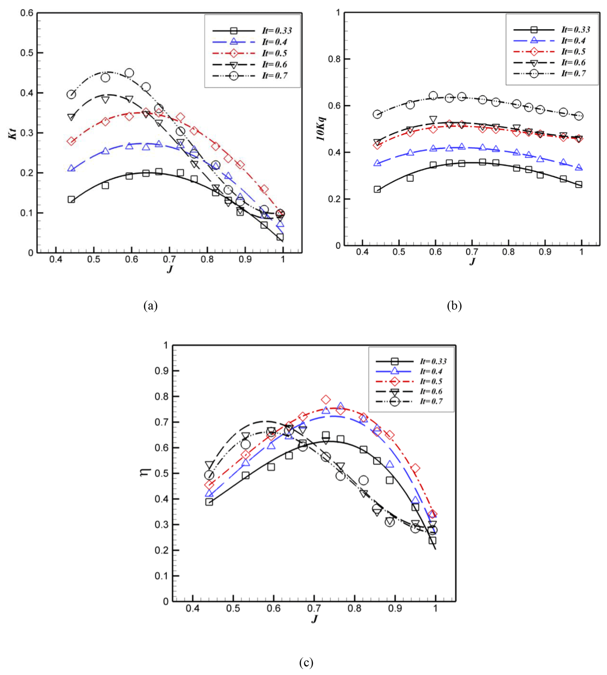
Figure 12Hydrodynamic coefficients and efficiency of a surface-piercing propeller for a 0 shaft degree and different immersion ratios.
Figure 12 shows the transition region for a 33 %–50 % immersion ratio at Ja=0.67. As seen by an increase in the immersion ratio, the critical advance coefficient reduces. Figure 12c shows that in low advance coefficients, the efficiency increases by the increase in the immersion ratio, while in a high advance coefficient the efficiency increases for the immersion ratio up to 50 % and then decreases. As seen at 0∘ shaft inclination, the maximum efficiency in all advance coefficients occurs at a 50 % immersion ratio. The maximum efficiency changes from 65 % to 33 % when the immersion ratio changes from 78 % to 50 %. The highest efficiency in all immersion ratios was achieved for shaft inclination 0∘. This result is not consistent with the results of Ferrando et al. (2007) and Dyson (2000) in which the immersion ratio had no significant effect on changing the efficiency of the propeller, and its increase only increased the thrust and torque.
In Misra's study (2012) on four-blade propellers with different geometries, the maximum efficiency occurred at a 50 % immersion ratio. The experimental results for the four-blade propellers also showed that with increasing the immersion ratio for the propellers, the maximum efficiency reduces from 61 % in the 30 % immersion ratio to 27 % in the 70 % immersion ratio. Therefore, the results indicate that for each propeller with different geometrical characteristics and profiles, a different result can be observed for the effect of the immersion ratio on efficiency. Figure 13 shows the effect of immersion ratio on the hydrodynamic coefficients and propeller efficiency at 10∘ shaft inclination. As seen by increasing the immersion ratio, the thrust and torque increase. With increasing the immersion ratio from 40 % to 60 %, and in high advance coefficients, the thrust will slightly increase in a certain advance coefficient. Figure 13c shows that the maximum efficiency ranges from 30 % at a 33 % immersion ratio to 41 % at a 40 % immersion ratio, which is the highest efficiency in all immersion ratios and advance coefficients (for 10∘ shaft inclination). This means that despite the 0∘ shaft inclination, the maximum efficiency occurs at a 40 % immersion ratio. Therefore, the propeller's location angle has an impact on maximum efficiency at a different immersion ratio. Figures 12 and 13 show that by increasing the immersion ratio, KT and KQ will significantly increase. Propeller efficiency is maximum at a 40 %–50 % immersion ratio. When higher thrust is needed without exceeding the allowable torque, increase in the immersion ratio can be useful or vice versa; when thrust condition is met but torque exceeded the limit, reducing the immersion can help to reach an optimum condition.
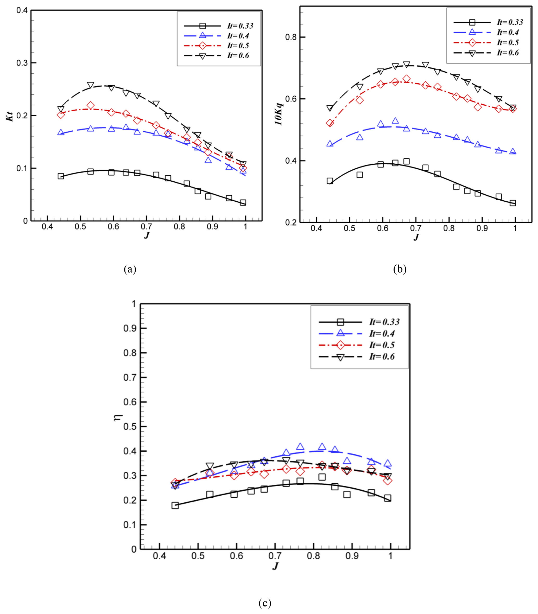
Figure 13Hydrodynamic coefficients and efficiency for the surface-piercing propeller at 10∘ shaft inclination and different immersion ratios.
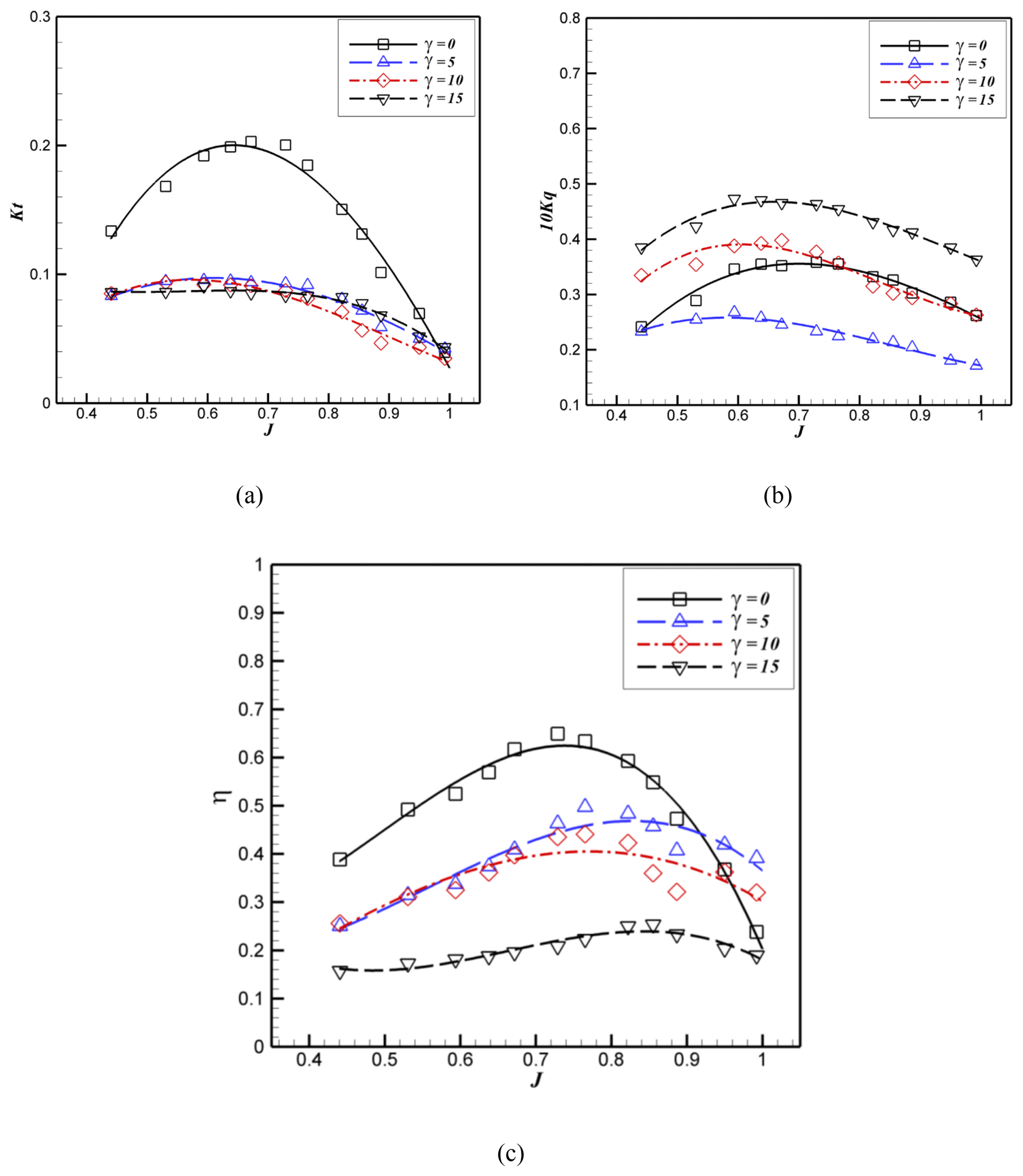
Figure 14Effect of the shaft inclination angle on the hydrodynamic coefficients and efficiency of the surface-piercing propeller at 33 % immersion ratio.
This section examines the effect of shaft inclination angle on the hydrodynamic coefficients and efficiency of the propeller at a fixed immersion ratio. By keeping the immersion ratio constant, and changing the shaft inclination ratio, significant patterns occur in the thrust, torque, and efficiency of the propellers which are shown in Fig. 14 for the 33 % immersion ratio. By changing the shaft inclination angle from 0 to 5, the thrust will significantly reduce and, with further increase in the inclination angle, although the thrust decreases, these coefficients are close to each other (see Fig. 14a). By increasing the shaft inclination angle, the critical advance coefficient reduces. The effect of the free surface also decreases and changes from a partially ventilated phase to a total fully ventilated phase. As seen in Fig. 14b, the variation of torque with changing the shaft inclination angle is contrary to the thrust variation. The torque decreases for the shaft inclination angle from 0 to 5∘ and then increases beyond with further increase in the shaft inclination. A similar observation was reported by Lorio (2011) in which with the increase in the shaft inclination angle, the thrust remained constant and torque increased. Oloffson (1996) concluded that at 33 % immersion ratio, by increasing the shaft inclination angle from 0 to 5, both thrust and torque increase. As seen in Fig. 14c, the efficiency reduces by increasing the shaft inclination angle such that the maximum efficiency reduces from 65 % in 0∘ to 25 % at 15∘ (reduces by 60 %). In other words, by increasing the shaft inclination angle from 0 to 15, the maximum efficiency reduces by 15 %. The reason for this significant decrease, according to Eq. (4), is the decrease in thrust and increase in torque. Changing the shaft inclination angle will change the force imposed on the propeller. This reduces the thrust and influences the efficiency and performance of the propeller.
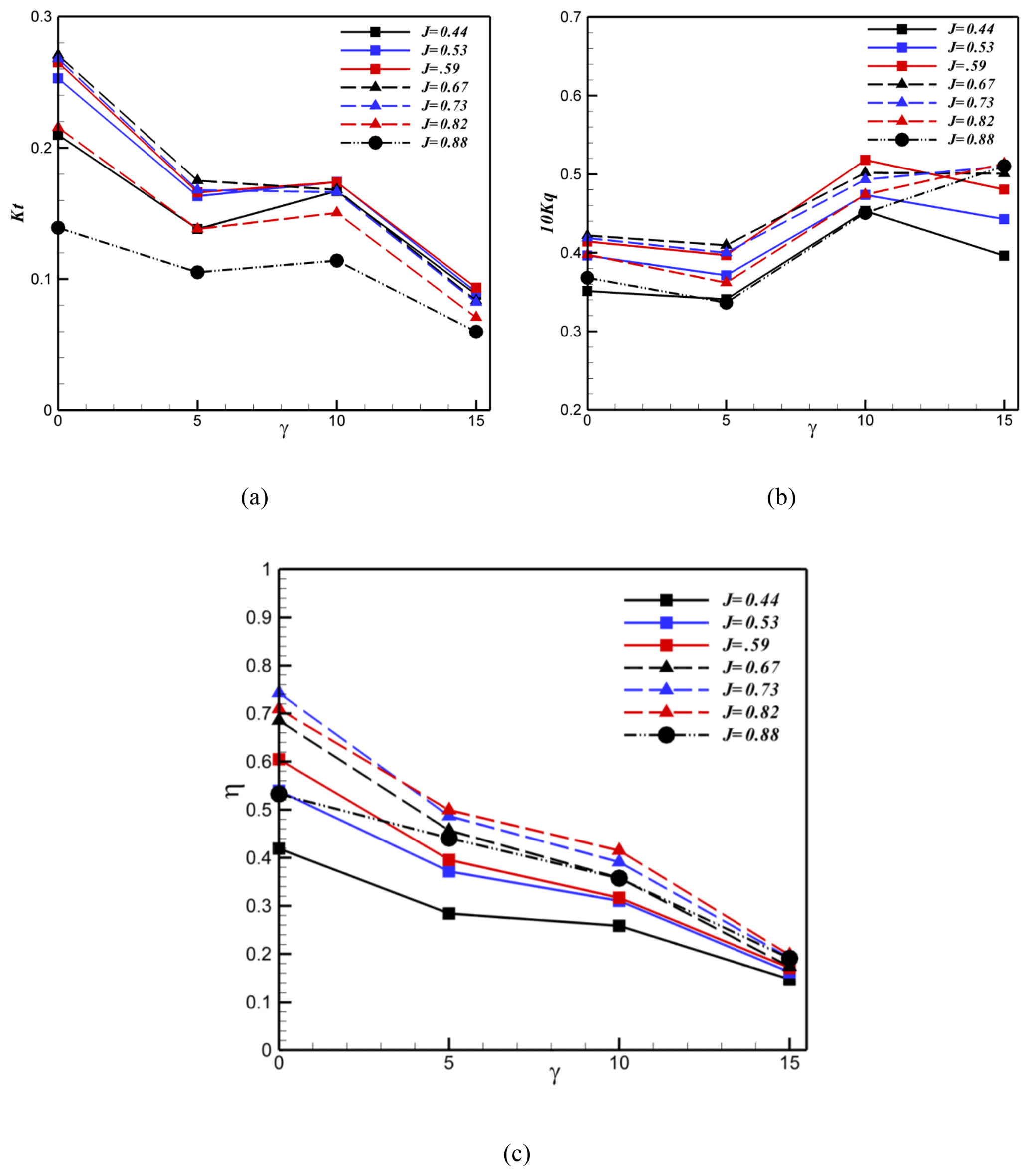
Figure 15Effect of shaft inclination angle on the hydrodynamic coefficients and efficiency of the surface-piercing propeller at different advance coefficients and 40 % immersion ratio.
The effect of shaft inclination angle on the thrust hydrodynamic coefficient at 40 % immersion ratio and different advance coefficients is shown in Fig. 15. According to this figure, the thrust reduces by increasing the shaft inclination angle. As seen at and , the maximum thrust occurs at J=0.67, and by increasing the shaft inclination ratio, the critical advance coefficient reduces to J=0.59. The maximum and minimum thrusts in all advance coefficients occur at and . In Fig. 15b, by increasing the shaft inclination angle, initially, the torque reduces at and, then, it increases except for the fully ventilated area in which the propeller is under a heavy load. Based on Fig. 15c, by increasing the shaft inclination angle, the efficiency reduces in all advance coefficients due to a simultaneous reduction of the thrust and increase in the torque. The maximum efficiency also occurs at 0∘ shaft inclination angle. According to Fig. 15, it can be concluded that at 30 % immersion ratio, the increase in the shaft inclination angle reduces the thrust and efficiency and increases the torque.
Similarly to Fig. 15, Fig. 16 shows the effect of shaft inclination angle on the hydrodynamic coefficients and efficiency at a 60 % immersion ratio. According to this figure, by increasing the shaft inclination angle, the thrust reduces. On the other hand, the torque increases by an increase in the shaft inclination angle, except at 15∘. Comparing the torque in Figs. 15 and 16 shows that the torque variation depends on the immersion ratio, in addition to the shaft inclination angle. According to Fig. 16c, the maximum efficiency was obtained at a 0∘ shaft inclination angle (low advance coefficients) and the minimum efficiency at 15∘ shaft inclination. Therefore, by increasing the shaft inclination angle, the efficiency decreases.
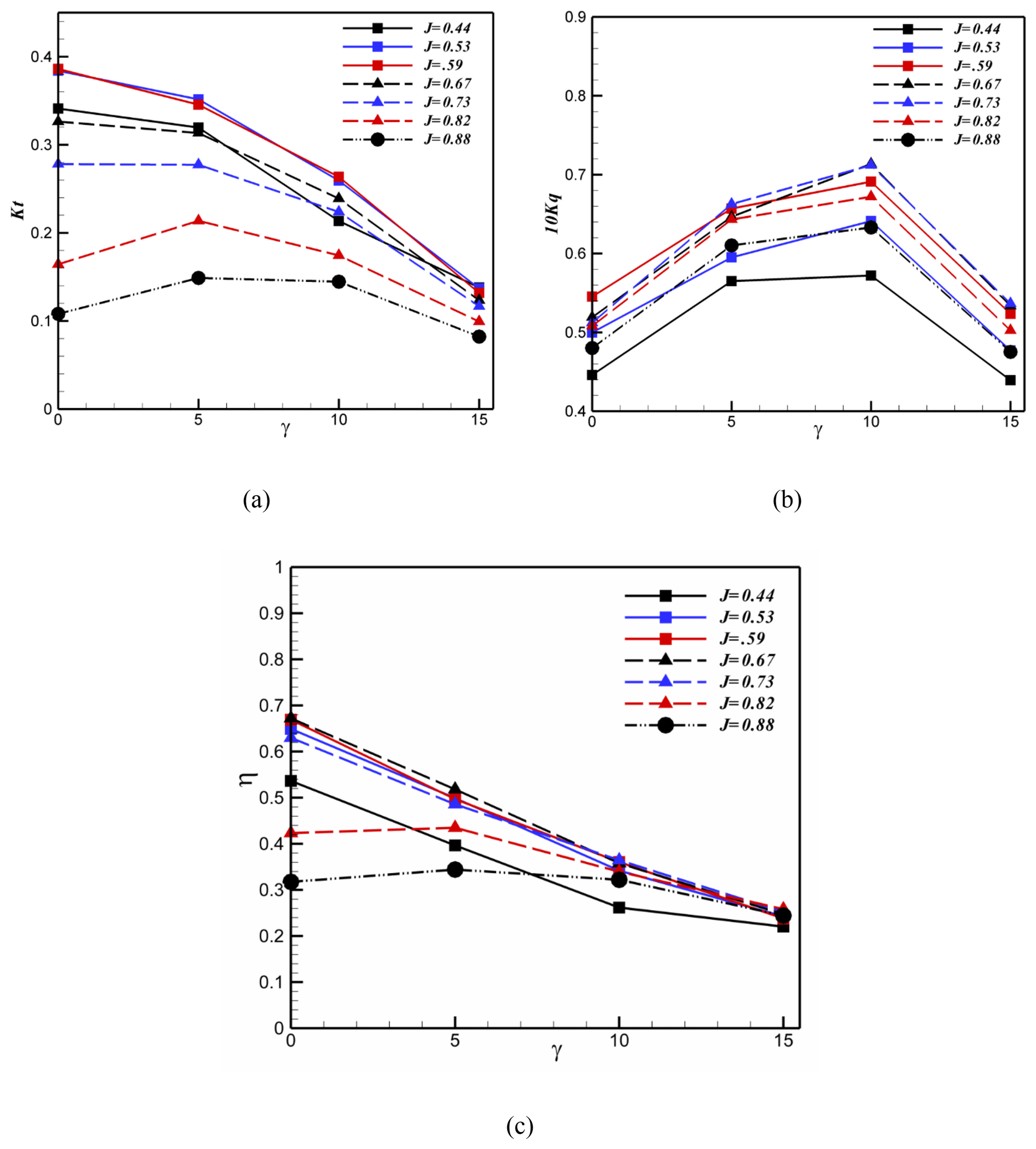
Figure 16Effect of shaft inclination angle on the hydrodynamic coefficients and efficiency of the surface-piercing propeller at different advance coefficients and 60 % immersion ratio.
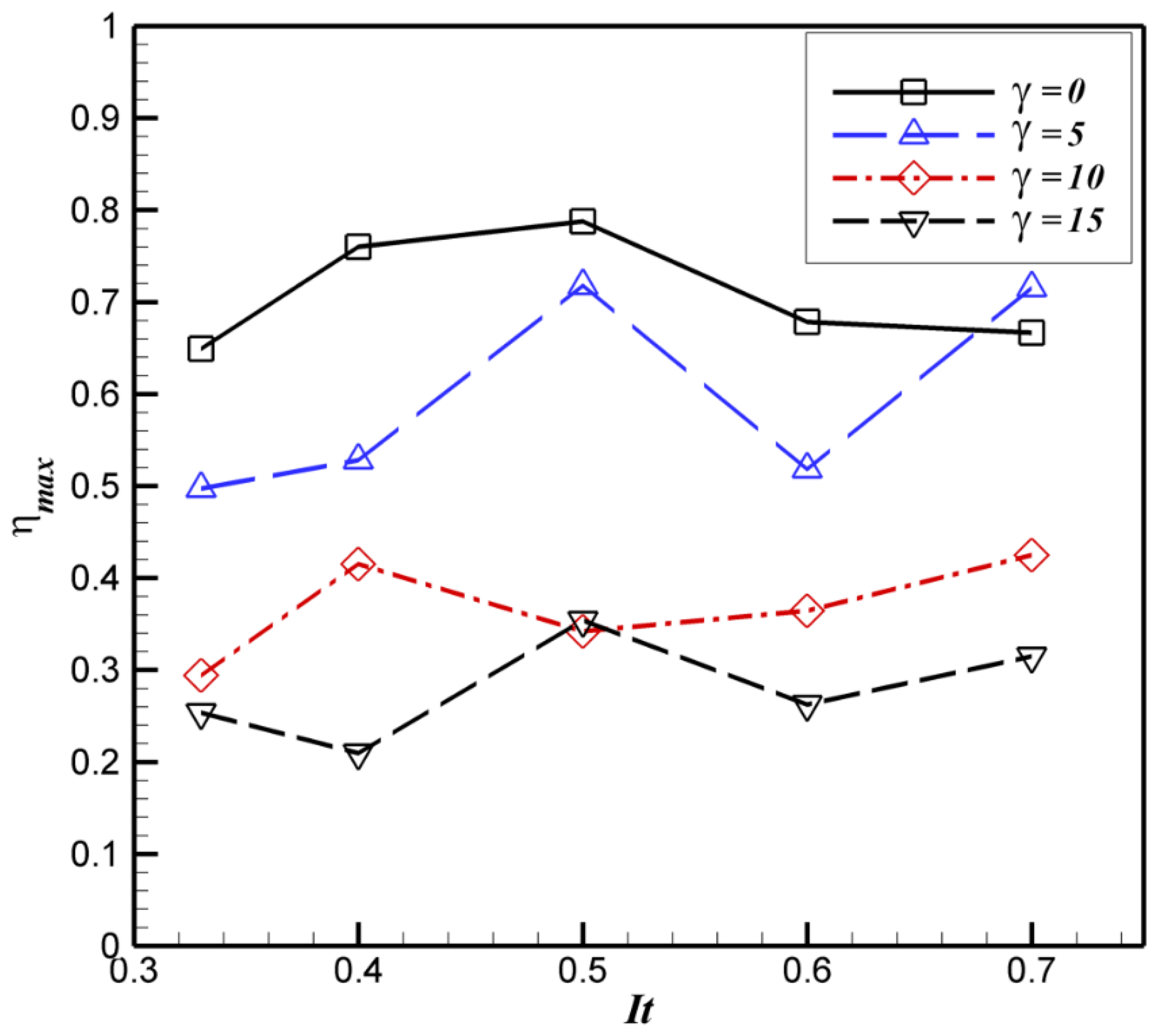
Figure 17Variation of maximum efficiency at different immersion ratios and shaft inclination angles.
Figure 17 shows the maximum efficiency variations of propellers for all immersion ratios and shaft inclination angles. As seen by increasing the immersion ratio at , the maximum efficiency increases from 64 % at 33 % immersion ratio to 78 % at 50 % immersion ratio, and after that decreases to 66 % at 70 % immersion ratio. It is also clear that by increasing the shaft inclination angle, except at 70 % immersion ratio, the maximum efficiency reduces. In all shaft inclination angles, except 0∘ shaft inclination, the maximum efficiency is at 50 % immersion ratio. The best position for installing of the propeller in this research is at 50 % immersion ratio and , because a propeller has the highest efficiency.
In this study, the importance of hydrodynamic coefficients such as thrust, torque, and efficiency of surface-piercing propeller were investigated experimentally. Due to the lack of available data for the five-blade propellers, a free surface water tunnel was used to test a five-blade surface-piercing propeller with a pitch ratio of 1.52. Variation of propeller geometrical specifications and their influences on the performance of the propellers were studied by changing the effect of immersion ratios (four values), shaft inclination angle (three values), and different advance coefficients. The results of obtained hydrodynamic coefficients were compared to the data from the available semi-empirical equations in the literature to provide a suitable evaluation for the accuracy of these equations.
The obtained results can be summarized as follows.
- a.
Studies showed that the accuracy of the semi-empirical equations presented by Ferrando et al. (2007) is higher than equations presented by Montazeri and Ghassemi (2009); however, none of these equations has enough accuracy.
- b.
The semi-empirical equations in different geometrical conditions are not reliable, and these equations cannot be used in many design conditions.
- c.
By increasing the immersion ratio, the critical advance coefficients (in which the transition from the partially ventilated to fully ventilated occurs) reduces.
- d.
The thrust and torque hydrodynamic coefficients increase by increasing the immersion ratio, but efficiency may slightly increase or decrease.
- e.
By increasing the shaft inclination angle, both thrust and efficiency reduce and the torque increases.
- f.
For all shaft inclination angles, the maximum efficiency is in the 40 %–50 % immersion ratio.
- g.
For all immersion ratios, the maximum efficiency occurs at a 0∘ shaft inclination ratio and the minimum efficiency at a 15∘ shaft angle inclination.
- h.
The best condition to install the propeller is 50 % immersion and because a propeller has the highest efficiency.
- i.
Experimental data of this study can be used to adjust the results and improve the accuracy of the semi-experimental equations.
All the data used in this paper can be obtained by request from the corresponding author.
SMS and MS conducted experiments, analyzed data and wrote the manuscript with support from RS. RS verified the results and supervised the whole project.
The authors declare that they have no conflict of interest.
The authors gratefully acknowledge use of the facilities of the Sea-Based Energy Research Group at the Babol Noshirvani University of Technology.
This paper was edited by Amin Barari and reviewed by three anonymous referees.
Ding, E.: A Series of Surface Piercing Propellers and Its Application, Proc., 9th International Conference on Fats Sea Transportation, Shanghai, China, 2007.
Dyson, P. K.: The modelling, testing and design, of a surface piercing propeller drive, PhD thesis, University of Plymouth, 2000.
Ferrando, M. and Scamardella, A.: Surface piercing propellers: Testing methodologies, results analysis and comments on open water characteristics, Proceedings: Small Craft Marine Engineering Resistance & Propulsion Symposium, 1996.
Ferrando, M., Viviani, M., Crotti, S., Cassella, P., and Caldarella, S.: Influence of Weber number on Surface Piercing Propellers model tests scaling, Proceedings of 7th International Conference on Hydrodynamics (ICHD), Ischia, Department of Naval Architecture and Ocean Engineering, Seoul National University, 4–6, 2006.
Ferrando, M., Crotti, S., and Viviani, M.: Performance of a family of surface piercing propellers, Proceedings of 2nd International Conference on Marine Research and Transportation (ICMRT), Ischia, available at: http://resolver.tudelft.nl/uuid:2b6e716b-a7c8-4601-ae60-3b80186f5abf (last access: 3 June 2019), 28–30, 2007.
Ghassemi, H. and Ghiasi, M.: Hydrodynamic Performance of Semi-submerged Propellers for Racing Boats, J. Ship Technol., 7, 16–31, 2011.
Hadler, J. and Hecker, R.: Performance of partially submerged propellers, 7th ONR Symposium on Naval Hydrodynamics, Rome, Italy, 25–30 August 1968.
IMO: International shipping facts and figures – information resourceson trade, safety, security, enviroment, Maritime Knowledge, International Martitime Organization, 2012.
Kruppa, C.: Testing of partially submerged propellers, 13th International Towing Tank Conference, Berlin/Hamburg, ITTC, 1972.
Liu, S. and Zhu, H.: An experimental study on the performance characteristics of partially submerged propeller, International High Performance Vehicle Conference, Shanghai, China, Chinese Society of Naval Architecture and Marine Engineering, 1988.
Lorio, J. M.: Open Water Testing of a Surface Piercing Propeller with Varying Submergence, Yaw Angle and Inclination Angle, Master of Science in Ocean Engineering, The College of Engineering and Computer Science, Boca Raton, Florida, 2011.
Misra, R. P. G. S. C., Sha, P., Suryanarayana, Ch., and Suresh, R. V.: Development of a Four-Bladed Surface Piercing Propeller Series, Naval Eeng. J., 105–138, 2012.
Montazeri, N. and Ghassemi, H.: Ditermination of hydrodynamic coefficients of surface-piercing propeller by regression method, 6th annual conference of design principles and applications of high speed craft, Iran, 2009 (in Persian).
Nozawa, K. and Takayama, N.: Experimental study on propulsive performance of surface piercing propeller, Journal of the Kansai Society of Naval Architects Japan, 2002, 63–70, 2002.
Olofsson, N.: Force and flow characteristics of a partially submerged propeller, Chalmers University of Technology, 1996.
Pustoshny, A. V., Bointsov, V. P., Lebedev, E. P., and Stroganov, A. A.: Development of 5-blade SPP series for fast speed boat, 9th International Conference on Fast Sea, Shanghai, China Ship Scientific Research Center, 2007.
Rose, J. and Kruppa, C.: Methodical Series Model Test Results, 1st International Conference on Fast Sea Transportation, Trondheim, Norway, TAPIR Publishers, 1991.
Rose, J., Kruppa, C., and Koushan, K.: Surface Piercing Propellers-Propeller/Hull Interaction, 2nd International Conference on Fast Sea Transportation, Yokohama, Japan, Society of Naval Architects of Japan, 1993.
Seyyedi, S. M. and Shafaghat, R.: Design Algorithm of a Free Surface Water Tunnel to Test the Surface-Piercing Propellers (SPP); Case Study Water Tunnel of Babol Noshirvani University of Technology, Int. J. Marit. Technol., 6, 19–30, 2016.
Shafaghat, R., Donyavizadeh, N., and Mohammadzadeh, S.: Investigation of effect weight of parameteres affecting the hydrodynamic coefficients in design of surface-piercing propellers, J. Mar. Sci. Technol., 17, 45–57, https://doi.org/10.22113/jmst.2017.42946.
Shiba, H.: Air-Drawing of Marine Propellers, Transportation Technical Research Institute, Report, 1953.
Shields, C. E.: Performance characteristics of several partially submerged super-cavitating propellers, Dept. of the Navy, Naval Ship Research and Development Center, DTIC Document, 1968.
- Abstract
- Introduction
- Effective parameters in designing surface-piercing propellers
- Laboratory equipment and calibration
- Model propeller specification
- Test conditions for the surface-piercing propeller
- Validation of results
- Results and discussion
- Conclusion
- Data availability
- Author contributions
- Competing interests
- Acknowledgements
- Review statement
- References